Table of Contents
Advertisement
This insert can be used in the following
mantel and fireplace systems:
FBNSD400RT-A-(AS,CH,TA,W)
HNS400RT-MV-(WC,AS)
WARNING: If the information in this manual is not
followed exactly, a fire or explosion may result causing
property damage, personal injury or loss of life.
— Do not store or use gasoline or other flammable va-
pors and liquids in the vicinity of this or any other
appliance.
— WHAT TO DO IF YOU SMELL GAS
• Do not try to light any appliance.
• Do not touch any electrical switch; do not use any
phone in your building.
• Immediately call your gas supplier from a neighbor's
phone. Follow the gas supplier's instructions.
• If you cannot reach your gas supplier, call the fire
department.
— Installation and service must be performed by a quali-
fied installer, service agency or the gas supplier.
WARNING: This appliance is equipped for natural and
propane/LP gas. Field conversion is not permitted other
than between natural or propane/LP gases.
Questions, problems, missing parts? Before returning to your retailer, call
our customer service department at 1-866-573-0674, 7:30 am - 4:15 pm CST,
Monday through Friday or email customerservice@usaprocom.com
VENT-FREE GAS SYSTEM
OWNER'S OPERATION
AND INSTALLATION
MANUAL
MODELS
FBNSD400RT SERIES
PFS
®
US
Advertisement
Table of Contents

Related Manuals for Procom FBNSD400RT Series


Summary of Contents for Procom FBNSD400RT Series
- Page 1 VENT-FREE GAS SYSTEM OWNER'S OPERATION AND INSTALLATION MANUAL MODELS FBNSD400RT SERIES This insert can be used in the following ® mantel and fireplace systems: FBNSD400RT-A-(AS,CH,TA,W) HNS400RT-MV-(WC,AS) WARNING: If the information in this manual is not followed exactly, a fire or explosion may result causing property damage, personal injury or loss of life.
-
Page 2: Table Of Contents
* Aftermarket: Completion of sale, not for purpose of resale, from the manufacturer. PROCOM HEATING, INC. PATENT INFORMATION This product may be covered by one or more of the following United States patents:... -
Page 3: Safety
SAFETY IMPORTANT: Read this owner’s WARNING: Any change to manual carefully and completely this heater or its controls can before trying to assemble, op- be dangerous. erate, or service this heater. Improper use of this heater can WARNING: Do not use a cause serious injury or death blower insert, heat exchange from burns, fire, explosion,... - Page 4 SAFETY 1. Do not place Propane/LP supply tank(s) 10. Turn off and unplug heater and let cool inside any structure. Propane/LP supply before servicing. Only a qualified service tank(s) must be placed outdoors. person should service and repair heater. 2. This heater should not be installed in a 11.
-
Page 5: Specifications
SPECIFICATIONS MODEL FBNSD400RT Gas Type Natural Propane/LP Maximum Input Rating 32,000 BTU/Hr 32,000 BTU/Hr Minimum Input Rating Regulator Pressure Setting 4" W.C. 9" W.C. Inlet Gas Pressure* Max. 9" W.C. Max. 14" W.C. (inches of water) Min. 5" W.C. Min. 11" W.C. * For purposes of input adjustment. -
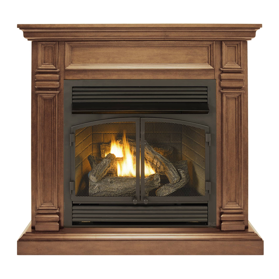
Page 6: Product Identification
PRODUCT IDENTIFICATION Hood Screen Logs Heater Controls (Inside Panel) Figure 1 - Vent-Free Fireplace Insert UNPACKING 1. Remove top inner pack. 6. Hold the screen, lift, and pull forward. 2. Tilt carton so that heater is upright. 7. Remove log set by cutting plastic ties. 3. -
Page 7: Water Vapor: A By-Product Of Unvented Room Heaters
WATER VAPOR: A BY-PRODUCT OF UNVENTED ROOM HEATERS Water vapor is a by-product of gas combus- The following steps will help ensure that water tion. An unvented room heater produces ap- vapor does not become a problem. proximately one (1) ounce (30 mL) of water 1. - Page 8 AIR FOR COMBUSTION AND VENTILATION VENTILATION AIR Ventilation Air From Outdoors Provide extra fresh air by using ventilation Ventilation Air From Inside Building grills or ducts. You must provide two perma- This fresh air would come from an adjoining nent openings: one within 12" of the ceiling unconfined space.
-
Page 9: Installation
This firebox may only be in- the house. Inspect chimney flue stalled in a ProCom Heating, Inc. and firebox for damage. If dam- mantel accessory approved for aged, repair flue before operat- this product. - Page 10 INSTALLATION GAS SELECTION Insert Gas Fitting Insert Gas Fitting This appliance is factory for Propane/LP Gas for Natural Gas preset for propane/LP gas. No changes are required for connecting to propane/LP. Only a qualified installer or service technician can perform gas selec- tion and connecting to gas supply.
- Page 11 INSTALLATION 2. Apply thread sealant to the threads on Use only the cap supplied on the the connection fitting. While pushing in, regulator. Do not use an off the rotate the fitting clockwise until the threads shelf pipe plug. This can damage engage the regulator.
- Page 12 Measure from outermost point of heater. Note: This firebox can not be installed in an existing fireplace. Install this firebox only in a ProCom Heating, Inc. mantel accessory approved for this product. Minimum Clearances For Side Combustible Material, Side Wall...
- Page 13 INSTALLATION CONNECTING TO GAS SUPPLY WARNING: A qualified ser- CAUTION: For natural gas, vice technician must connect check your gas line pressure heater to gas supply. Follow all before connecting heater to gas local codes. line. Gas line pressure must be no greater than 9"...
- Page 14 INSTALLATION Typical Inlet Pipe Diameters reduce incoming gas pressure to between 11" Use 3/8" black iron pipe or greater. Installa- and 14" of water. If you do not reduce incom- tion must include an equipment shutoff valve, ing gas pressure, heater regulator damage union, and plugged 1/8"...
- Page 15 INSTALLATION CHECKING GAS CONNECTIONS Open Equipment WARNING: Test all gas piping Shutoff Valve and connections, internal and external to unit, for leaks after installing or servicing. Correct Closed all leaks at once. Figure 9 - Equipment Shutoff Valve Equipment WARNING: Never use an open Propane/LP Shutoff Valve Supply Tank...
- Page 16 INSTALLATION INSTALLING LOGS 6. Insert the pin on log #6 into the hole on WARNING: Failure to posi- log #3 (see Figures 14 and 15, page 17). tion the parts in accordance IMPORTANT: Make sure logs do not cover with these diagrams or failure any burner ports.
- Page 17 INSTALLATION Hole for Log #6 Pin for Log #5 Log #5 Log #6 Log #4 Figure 15 - Installing Log #5 and #6 Figure 14 - Installing Log #4 INSTALLING BATTERIES CAUTION: Do not mix old and new batteries. Do not mix alka- line, standard (carbon - zinc), or Battery Positive...
-
Page 18: Operation
OPERATION FOR YOUR SAFETY READ BEFORE LIGHTING not use any phone in your building. WARNING: If you do not fol- • Immediately call your gas supplier low these instructions exactly, from a neighbor’s phone. Follow the a fire or explosion may result gas supplier’s instructions. - Page 19 OPERATION 8. With control knob pressed in, push Note: If burner does not light, push the down and release ignitor button. This slide switch on the receiver box to the OFF will light pilot. The pilot is attached to position, then back to the ON position. the rear of the burner.
- Page 20 OPERATION REMOTE CONTROL SYSTEM Programming the Remote and Receiver Key Settings The remote and receiver must be “learned” ON - Operates unit to on position, manually to one another. operated solenoid ON. To prepare the receiver box for learning, use OFF - Operates unit to off position, manually a pen or small screwdriver to gently press operated solenoid OFF.
- Page 21 OPERATION Setting°F/°C Scale 2. Press and hold the SET key until the de- The factory setting for temperature is °F. To sired set temperature is reached. The LCD change this setting to °C, press the ON key screen set numbers will increase from 45° and the OFF key on the remote control at the to 99°...
-
Page 22: Inspecting Burners
INSPECTING BURNERS IMPORTANT: Owner’s should check pilot flame pattern and burner flame pattern often. Incorrect flame patterns indicate the need for cleaning (see Care and Maintenance, page 23) or service. WARNING: Only a qualified service person should service and repair heater. This includes maintenance requiring replacement or alteration of components. -
Page 23: Care And Maintenance
CARE AND MAINTENANCE WARNING: Turn off heater and let cool before servicing. CAUTION: You must keep control areas, burner, and circulating air passageways of heater clean. Inspect these areas of heater before each use. Have heater inspected yearly by a qualified service techni- cian. - Page 24 CARE AND MAINTENANCE ODS/PILOT Ignitor Natural Gas Thermocouple CAUTION: Never use a wire, Electrode Burner needle, or similar object to clean Propane/LP Gas Burner ODS/pilot. This can damage ODS/ pilot unit. Use a vacuum cleaner, pressurized air, or a Pilot Air small, soft bristled brush to clean.
-
Page 25: Troubleshooting
TROUBLESHOOTING WARNING: If you smell gas: • Shut off gas supply. • Do not try to light any appliance. • Do not touch any electrical switch; do not use any phone in your building. • Immediately call your gas supplier from a neighbor’s phone. Fol- low the gas supplier’s instructions. - Page 26 TROUBLESHOOTING Problem Possible Cause Corrective Action When ignitor button is 1. Ignitor electrode is posi- 1. Replace electrode. pressed in, there is no tioned wrong. Ignitor elec- spark at ODS/pilot. trode is broken. 2. Ignitor electrode is not con- 2. Replace ignitor cable. nected to ignitor cable.
- Page 27 TROUBLESHOOTING Problem Possible Cause Corrective Action Burner does not light after 1. Burner orifice is clogged. 1. Clean burner orifice (see ODS/pilot is lit. Care and Maintenance, page 23) or replace burner orifice. 2. Burner orifice diameter is too 2. Replace burner orifice. small.
- Page 28 TROUBLESHOOTING Problem Possible Cause Corrective Action Heater produces a click- 1. Metal is expanding while 1. This is common with most ing/ticking noise just after heating or contracting while heaters. If noise is exces- burner is lit or shut off. cooling.
-
Page 29: Replacement Parts
1-866-573-0674 for referral information. ACCESSORIES Purchase these heater accessories from your local dealer. If they can not supply these ac- cessories, contact ProCom Heating, Inc. at 1-866-573-0674 for information. EQUIPMENT SHUTOFF VALVE For all models. Equipment shutoff valve with 1/8" NPT tap. -
Page 30: Parts
PARTS MODELS FBNSD400RT PIL OT TEMP www.usaprocom.com 200228-01A... - Page 31 PARTS MODELS FBNSD400RT This list contains replaceable parts used in your heater. When ordering parts, follow the instructions listed under Replacement Parts on page 29 of this manual. ITEM PART # DESCRIPTION FHL008-02D Hood FBB102 Louver FBB104BL Left Door Assembly FBB104BR Right Door Assembly ND0310A-400-P...
-
Page 32: Warranty
We make no other warranty, expressed or implied. LIMITED WARRANTY ProCom Heating, Inc. warrants this product to be free from defects in materials and components for ONE (1) year from the date of first purchase, provided that the product has been properly installed by a qualified installer in accordance with all local codes and instructions furnished with the unit, operated and main- tained in accordance with all applicable instructions.
Need help?
Do you have a question about the FBNSD400RT Series and is the answer not in the manual?
Questions and answers