Table of Contents
Advertisement
Quick Links
Questions about installation, Operation or troubleshooting?
Before returning to your retailer, contact our customer service department at 1-877-886-5989,
8:00a.m.—4:30p.m., EST, Monday—Friday or e-mail customerservice@usaprocom.com.
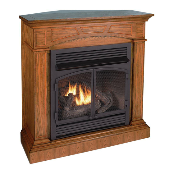
CORNER COMBO
WOOD FIREPLACE MANTEL
Model #
FBD400TCC-M-HC/MO
FBD400RTCC-M-HC/MO
PC-FBD400-M3-1101
Advertisement
Table of Contents

Related Manuals for Procom FBD400TCC-M-HC/MO


Summary of Contents for Procom FBD400TCC-M-HC/MO
- Page 1 CORNER COMBO WOOD FIREPLACE MANTEL Model # FBD400TCC-M-HC/MO FBD400RTCC-M-HC/MO Questions about installation, Operation or troubleshooting? Before returning to your retailer, contact our customer service department at 1-877-886-5989, 8:00a.m.—4:30p.m., EST, Monday—Friday or e-mail customerservice@usaprocom.com. PC-FBD400-M3-1101 ...
-
Page 2: Product Specifications
PRODUCT SPECIFICATIONS ... -
Page 3: Package Contents
PACKAGE CONTENTS If a part is missing or damaged - return to place of purchase (exterior wood components are not replaceable). PART DESCRIPTION QUANTITY Panel Left Upper Panel Right Upper Panel Left Lower Panel Right Lower Panel Base Top Triangle Panel Backboard Set Square Support ... -
Page 4: Hardware Contents
HARDWARE CONTENTS Picture Picture Part Description Quantity Part (Shown to size) Description Quantity (Shown to size) ST4 Screw Cam Dowel 5/8 in. Connector Cam Lock Bracket Wall Anchor White Key ST4 Screw ST4 Screw 1 -9/16 in. 1 -3/16 in. - Page 5 ASSEMBLY INSTRUCTIONS Fig 1 1. Fasten the Left Upper Panel (C) and the Left Lower Panel (E) with M6 Screw 1-3/8 in. (JJ) as shown in Fig 1. Do the same thing for the Right Upper Panel (D) and the Right Lower Panel (F). Hardware Used M6 Screw ×4...
- Page 6 Fig 3 3. Insert Cam Locks (BB) into the Left Lower Panel (E) and the Right Lower Panel (F), screw in Cam Dowels (AA) into Base (G). Attach Base (G) into assembled frame (B, C, D, E, F) by tightening the Cam Locks (BB) as shown in Fig 3.
- Page 7 Fig 5 5. Insert Cam Locks (BB) into Panel (B), the Left Upper Panel (C) and the Right Upper Panel (D), screw in Cam Dowels (AA) into Top (A). Attach Top (A) into assembled frame (B, C, D, E, F) by tightening the Cam Locks (BB) as shown in Fig 5.
- Page 8 Fig 7 7. After assembling the mantel, lift upright and push the insert from the front of the mantel as shown in Fig 7. Fig 8 8. Position the fireplace to the desired place as shown in Fig 8. ...
- Page 9 FOR CORNER APPLICATION Fig 9 9. Turn the fireplace Top (A) Panel over. Using the Connector Brackets (GG) that supplied, connect the Fireplace Top (A) to the Top Triangle Panel (H) with ST4 Screw 5/8 in. (FF) as shown in Fig 9. Hardware Used ST4 Screw ×18...
- Page 10 Fig 11 11. Fasten the batten with ST4 Screw 1-9/16 in. (II) to the Top (A) as shown in Fig 11. Hardware Used ST4 Screw ×4 1 -9/16 in. Fig 12 12. Attach the left and right Backboard (I) trim pieces to the back of the fireplace with ST4 Screw 1-3/16 in.
- Page 11 Fig 13 13. After assembling the mantel, lift upright and push the insert from the front of the mantel as shown in Fig 13. Fig 14 14. Drill two holes (5/16 in) in the corner where the fireplace is to be displayed. Drill the first hole 44-1/2 in.
- Page 12 Fig 15 15. Attach the triangular wood block to the holes drilled in step 8 with ST5 Screw 2-3/8 in. (EE) as shown in Fig 15. This block is used to support the Set Square Support (J). For thin walls, insert white key (HH) into wall anchor and push to “pop”...
-
Page 13: Replacement Parts List
REPLACEMENT PARTS LIST Part Description Part # Quantity Hardware Package HP007 Cam Dowel PCAM-023 Cam Lock PCAM-023 Wall Anchor ML066-01 ST4 Screw 1-3/16 in. GB/T 951 4×30 ST5 Screw 2-3/8 in. GB/T 950 5×60 ST4 Screw 5/8 in. GB/T 951 4×16 Connector Bracket SJ002 White Key... -
Page 14: Warranty Information
WARRANTY INFORMATION Keep This Warranty IMPORTANT: We urge you to fill your warranty registration card within TEN(10) days of date of installation, complete with the entire serial number which can be found on the rating plate. Retain this portion of the card for your record. Always specify model and serial numbers when communicating with customer service.
Need help?
Do you have a question about the FBD400TCC-M-HC/MO and is the answer not in the manual?
Questions and answers