Free2Move eSolutions eProWallbox Installation Manual
Hide thumbs
Also See for eProWallbox:
- Installation manual (11 pages) ,
- Installation manual (32 pages) ,
- Quick installation manual (32 pages)

Related Manuals for Free2Move eSolutions eProWallbox


Summary of Contents for Free2Move eSolutions eProWallbox
- Page 1 I n s t a l l a t i o n M a n u a l For safe and proper use, follow these instructions. Keep them for future reference...
-
Page 2: Table Of Contents
Inst a llat io n M an ual TABLE OF CONTENT INTRODUCTION Purpose of the Manual 1.2 Identification of the Manufacturer Structure of the installation Manual Safety Personal Protective Equipment (PPE) Warranty and delivery conditions List of documents in the appendix Warnings GENERAL INFORMATION Fields of use 2.2 Symbols and definitions... - Page 3 Inst a llat io n M an ual 3.12 eProWallbox Display Screens 3.13 Parameter configuration after installation 3.14 Setting maximum power 3.15 Operating mode configuration 3.16 Wi-Fi setting COUNTRY SETTINGS Unbalanced load Randomized delay ADVANCED FUNCTIONS Master / Slave Backend connection setting Diagnostics TROUBLESHOOTING CLEANING...
-
Page 4: Introduction
S.p.A. but oversights cannot be completely ruled out. If any errors are noted, please inform Free2move eSolutions S.p.A. Except for explicit contractual obligations, under no circumstances may Free2move eSolutions S.p.A. be held liable for any loss or damage resulting from the use of this manual, or from installation of the equipment. - Page 5 The Unknown Services contains all the parameters that can be written and read through Bluetooth. Free2move eSolutions S.p.A. cannot be held liable for damage caused to persons and/ or property, or to the equipment, if the conditions described in this document have not been complied with.
-
Page 6: Personal Protective Equipment (Ppe)
Inst a llat io n M an ual Personal Protective Equipment (PPE) Personal Protective Equipment (PPE) means any equipment intended to be worn by the workers in order to protect them against one or more hazards likely to threaten their health or safety at the workplace, as well as any device or accessory intended for this purpose. -
Page 7: Warranty And Delivery Conditions
The warranty details are described in the Terms and Conditions of Sale included with the purchase order for this product and/or in the packaging of the product. Free2move eSolutions S.p.A. assumes no responsibility for failure to comply with the instructions for proper installation, and cannot be held responsible for systems upstream or downstream of the equipment supplied. -
Page 8: Warnings
• Children must not play with the device, accessories or packaging provided with the product. • The only part that can be removed from eProWallbox, is the removable cover. • eProWallbox can only be used with an energy source. -
Page 9: General Information
Inst a llat io n M an ual GENERAL INFORMATION eProWallbox is an Alternate Current charging solution for powering electric vehicles and hybrid plug-ins, and is ideal for semi-public and residential use. The appliance is available in three-phase or single-phase configurations, and is equipped with a Type 2 socket. The appliance charges electric vehicles up to 22 kW in three-phase, or up to 7.4 kW in single-phase. -
Page 10: Fields Of Use
Inst a llat io n M an ual Fields of use Free2move eSolutions S.p.A. declines all liability for any damage whatsoever due to incorrect or careless actions. The appliance is a charging device for electric vehicles; the following classification (according to IEC 61851-1) identifies its characteristics: • Power supply: permanently connected to the AC power supply grid •... -
Page 11: Symbols And Definitions
Inst a llat io n M an ual Symbols and definitions General warning It is mandatory to consult the original manual and additional documentation Prohibition or restrictions Although they are not made of materials that are harmful to health, the products should not be disposed of along with household waste but must be collected separately, since they are made of materials that can be recycled... -
Page 12: Identification Label
The Part Number (PN) and Serial Number (SN) can also be found on the packaging as well as in the eSolutions Charging app after pairing eProWallbox to the user’s profile and in PowerUp after pairing with QR code. The QR code is the same on... -
Page 13: Product Dimensions And Characteristics
Inst a llat io n M an ual Product dimensions and characteristics... -
Page 14: Technical Specifications
Inst a llat io n M an ual Technical specifications eProWallbox Description Recharging Mode Mode 3 - case B Connector Standard IEC 62196-2 Type2 Connection features Socket with lid and internal shutter Marking CE, UKCA, TUV, 3A General Specifications Dimensions [mm]... -
Page 15: Description Of Ports
Inst a llat io n M an ual Description of ports The following table summarises the ports available on eProWallbox: ETH 1x RFID reader (CN12) RS485 x1 DPM (SW1) Rotary Switch (CN9-CN10) RS485 x1 DC (CN3) Shunt Trip 4GLTE, WI-FI,... -
Page 16: Installation
(in the most serious cases, injuries may be fatal). Please read this manual carefully before installing, switching on and using the product. Free2move eSolutions S.p.A. recommends only using experienced professionals who comply with current regulations to install the product correctly. - Page 17 Inst a llat io n M an ual Before proceeding with the installation, make sure that: • The input power is completely switched off and remains in this condition until installation is complete. • As the work area is considered a dangerous zone it has been adequately cordoned off in order to prevent the access by persons not involved in the installation operations. The appliance is not installed in conditions of rain, fog or high humidity.
-
Page 18: Package Contents
Inst a llat io n M an ual Package Contents • eProWallbox • 3 ø10x50mm wall plugs with screws • 1 RFID Card • 1 drilling template for installation • Product documentation • 1 Sim Card installed • “C” label... -
Page 19: Required Tools
(not provided by the Manufacturer). WARNING Do not use an electrical screwdriver to assemble the wallbox or to fix it to the wall. Free2move eSolutions S.p.A. declines any liability for damage to persons or things arising from use of such tools. -
Page 20: Space And Positioning
In addition, the installation site must be sufficiently ventilated to ensure proper heat dispersion. NOTICE If eProWallbox connectivity is needed make sure that the chosen area is covered by mobile phone reception or by Wi-Fi coverage. Before installing, ensure that environmental conditions (such as temperature, altitude and humidity) comply with the appliance specifications. - Page 21 Inst a llat io n M an ual eProWallbox must not be installed in places: • characterised by potentially explosive atmospheres (according to 2014/24/ EU Directive) • used for escape routes • where articles may fall on it (e.g. suspended ladders or car tyres) or where it is likely to be hit and damaged (e.g.
-
Page 22: Wall Mounting
The national and international building regulations set out in IEC 60364-1 and IEC 60364-5-52 must be observed when fixing eProWallbox to the wall. Correct positioning of the charging station is important to ensure it operates correctly. To fix the main body to the wall, 3 plugs (Ø 10x50 mm) are required. The plugs supplied are universal and are suitable for solid or hollow brick walls. - Page 23 Secure the main body to the wall by inserting the screws through the holes. • Remove the external cover using the groove on the bottom. • eProWallbox by inserting the 3 screws in the wall plugs using the Philips-head screwdriver. •...
-
Page 24: Installation Of External Protection Devices
Therefore, in accordance with the IEC 61851-1 standard, the device must be protected upstream by externally installing the following electrical protection devices. eProWallbox is not equipped with a PEN fault detection system. Miniature Circuit Breaker (MCB): 1P/P3+N, recommended C curve, at least 6kA rated short-circuit capacity. -
Page 25: Power Supply Connection
Inst a llat io n M an ual Power supply connection The appliance must be powered by cables of an appropriate size and capable of withstanding the current for which the product has been designed. Make sure the cables are of a suitable size before wiring, and that the maximum permissible bending radius is not exceeded. - Page 26 Inst a llat io n M an ual NOTE The lower part of the device body has 2 side cable entry points which are closed with protective caps to prevent dust or moisture from entering during shipment. Power supply cables Communication cables Power supply cables Communication cables...
- Page 27 Inst a llat io n M an ual The following diagrams show how to electrically connect the device in single-phase or three-phase systems. CAUTION In the case of installations in three-phase systems, ensure that the electrical loads in the system (including the wallbox) are well balanced between the phases.
-
Page 28: Single-Phase Installation
Inst a llat io n M an ual 3.7.1 Single-phase installation In the case of single-phase installation, follow the steps below: • Remove the protective cap of the power supply cables entry and insert the Ø 25 mm corrugated sheath. •... -
Page 29: Three-Phase Installation
Inst a llat io n M an ual 3.7.2 Three-phase installation In the case of three-phase installation, follow the steps below: • Remove the protective cap of the power supply cables entry point and insert the Ø 25 mm corrugated sheath. •... -
Page 30: Connection Of The Communication Cable
Inst a llat io n M an ual Connection of the communication cable eProWallbox is equipped with 2 x RS485 ports for Modbus communication. Modbus RS485 is used to communicate with Accessories, such as the MIDcounter certified energy meter and PowerMeter (DPM) for Dynamic Power Management, or for the communication with external Energy Management Systems (EMS). - Page 31 • To perform a state-of-the-art installation, the communication cables must pass through the dedicated metal conduit inside the eProWallbox. • Connect the communication cable to the corresponding port (check the relevant chapter or the relevant manuals for details on installation of Accessories or Modbus).
-
Page 32: Installation In It Systems
Inst a llat io n M an ual Installation in IT systems To install eProWallbox in IT systems, remove the plastic film from the DIP Switch SW2 and move both contacts to the ON position. Then proceed with the installation. (SW2) -
Page 33: Setting The Power Supply Type And Maximum Power
Inst a llat io n M an ual 3.10 Setting the power supply type and maximum power It is mandatory during the installation phase to set the required type of power supply input (single-phase or three-phase) and maximum power, according to the maximum power that can be supplied by the electrical system. -
Page 34: Closing Operations And Power On
Inst a llat io n M an ual 3.11 Closing operations and power on Before closing, check to ensure that the power supply cables are connected properly, making sure that the respective positions of the phases and neutral in the CN1 terminal block respect the markings. To close, follow the steps below:. -
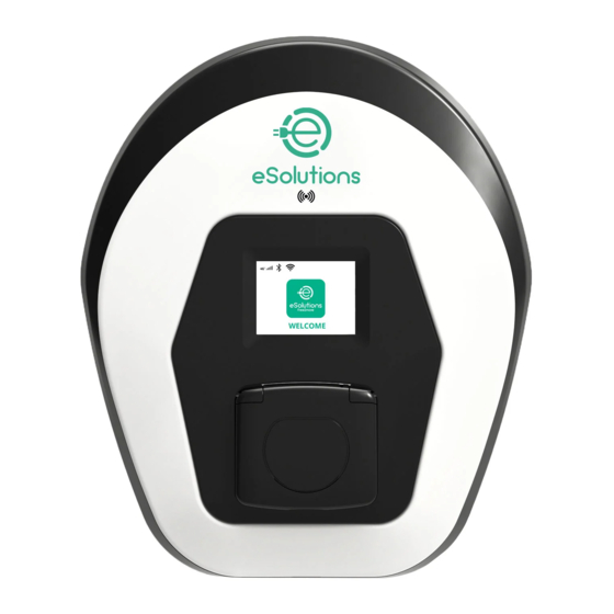
Page 35: Eprowallbox Display Screens
Inst a llat io n M an ual 3.12 eProWallbox Display Screens Once eProWallbox is powered on, the following screens appear on the display: Welcome message WELCOME This screen is the default one in Autostart mode. It instructs the operator to insert the charging cable, to start the charging session. - Page 36 Inst a llat io n M an ual This screen displays the w of the ongoing session: • TIME: Duration of the session • ENERGY: Energy absorbed by the vehicle • TIME ENERGY POWER POWER: Current charging power 0:00:00 00,00 00,00 If the DPM function is enabled the arrows on the bottom right will hour...
- Page 37 Inst a llat io n M an ual The screen shows that a software update is in progress. SOFTWARE UPDATE IN PROGRESS This screen will be displayed if scheduled charging is present on the wallbox for delayed charging sessions, recurrent charging profile limitation and Random delay.
-
Page 38: Parameter Configuration After Installation
Inst a llat io n M an ual 3.13 Parameter configuration after installation When the electrical installation is completed, eProWallbox needs to be configured through a Bluetooth connection using the dedicated installer App PowerUp, otherwise the wallbox cannot operate correctly. NOTICE PowerUp is a smartphone app to be used by qualified installers only, available via the Google Play™... -
Page 39: Setting Maximum Power
Operating mode 3.15 Operating mode configuration It is possible to configure eProWallbox to work in different Operating Modes, changing the charge authorization and connectivity options. It is possible to change the Operating Modes with the Autostart and Standalone toggles in PowerUp. - Page 40 Inst a llat io n M an ual eProWallbox has two Connectivity options: • Connectivity enabled (default factory setting): when the Standalone option is disabled, eProWallbox is connected to the eSolutions control platform (CPMS) to enable software updates, live remote Customer Care support and to enjoy the maximum functionalities of eSolutions Charging •...
-
Page 41: Wi-Fi Setting
Wi-Fi password Master / Slave Internet mobile pameters NOTICE At the first set-up, eProwallbox detects the same connection network of the smartphone, but it is also possible to manually insert the SSID of another Wi-Fi connection. NOTICE Once the function is enabled, to make the changes effective, always... -
Page 42: Country Settings
Inst a llat io n M an ual COUNTRY SETTINGS “Country settings” is a section of the app dedicated to the settings of functionalities for specific countries like “Unbalanced load” or “Random Delay”. Read below the specifications for each function. Unbalanced load “Unbalanced load” detection is a specific function for power management. According to relevant standards for specific countries, the current imbalance between the phases must not differ by more than a fixed value (different for each country). -
Page 43: Randomized Delay
Use the default value of 600 s as per the UK requirements This function can also be activated and deactivated by the user in the eSolutions Charging County settings Max A 32.00 eProWallbox Max kW 7.40 F2ME.EPROXXXXXXXX 0000AB0123456789 2.9.1 Load unbalance... -
Page 44: Advanced Functions
ADVANCED FUNCTIONS Master / Slave NOTICE The function is available starting with eProWallbox firmware version 2.9 and later. The Master/Slave function allows a group of eProWallboxes to be managed in a harmonized way. The main function of the Master/Slave is to manage the power distribution between the wallboxes of the group according to the maximum power available at the point of connection. - Page 45 Inst a llat io n M an ual • Using the communication cable (suggested in chapter 3.10) connect the wallboxes in daisy chain as indicated in the figure: CN10 CN10...
- Page 46 Inst a llat io n M an ual • Complete the installation with PowerUp. The configuration must be done for every eProWallbox installed in the Master/Slave group: • PowerUp scan the QR code of eProWallbox • Click on Master/Slave from the menu • The function is OFF by default, proceed to set: •...
- Page 47 Inst a llat io n M an ual • The communication speed: must be the same for every eProWallbox. It is recommended that the default setting is used: 115200 baud. • The communication channel: is the eProWallbox Address. This must be set as incremental following the order of electrical connection.
-
Page 48: Backend Connection Setting
Inst a llat io n M an ual Backend connection setting By default, eProWallbox is configured to connect to the eSolutions control platform (CPMS). When requested, eProWallbox can be connected to a third-party backend platform using OCPP 1.6 JSON protocol via 4G LTE, using a third-party SIM card or via Wi-Fi. - Page 49 Inst a llat io n M an ual Connect to eProWallbox with PowerUp and follow the actions below: • On the homepage, select “Parameters for mobile connection” • Select APN and set end point and credentials, if needed • Set the SIM card PIN, if needed •...
-
Page 50: Diagnostics
Inst a llat io n M an ual Diagnostics If an error occurs in eProWallbox, it is possible to check the troubleshooting in the dedicated section of PowerUp. In the main menu, go to the Diagnostics section. Here it is possible to find the list of errors in the eProWallbox and the detail of the event. -
Page 51: Troubleshooting
Make sure that the installation site is compatible with the temperature range (-25°C/+50°C without direct exposure to sunlight). Communication error Restart the eProWallbox from the circuit breaker, leaving the eProWallbox switched off for at least between MCU and 60 seconds. MPU. - Page 52 Check that the communication cable used is suitable for Modbus RS485 Check that the MID model configuration on PowerUp is correct. Inconsistency between the wallbox Restart the eProWallbox from the circuit breaker, leaving the eProWallbox switched off for at least contactor command 60 seconds. and feedback...
- Page 53 Check that the problem is not cable nor vehicle related and attempt another charging session (if disconnected). possible with another vehicle or another cable). Emergency stop Restart the eProWallbox from the circuit breaker, leaving the eProWallbox switched off for at least received from the 60 seconds. MPU.
-
Page 54: Cleaning
Inst a llat io n M an ual CLEANING Cleaning the outside of the device is always recommended when necessary and should be carried out using a soft damp cloth with a mild detergent. When finished, wipe off any traces of moisture or liquid with a soft dry cloth. CAUTION Avoid strong jets of air or water as well as the use of soaps or detergents that are too harsh and corrosive for the materials of the appliance. -
Page 55: Packaging Disposal
Further information about current disposal facilities can be obtained from local authorities. ASSISTANCE If you have any questions about the installation of eProWallbox, please contact your local authorised assistance centre through the appropriate Customer Support section at www.esolutions.free2move.com/contact-us. For any other information or requests for support, please contact Free2move eSolutions S.p.A. - Page 56 Inst a llat io n M an ual Registered office Free2move eSolutions S.p.A. Piazzale Lodi, 3 20137 Milan – Italy www.esolutions.free2move.com...
Need help?
Do you have a question about the eProWallbox and is the answer not in the manual?
Questions and answers