Sign In
Upload
Download
Table of Contents
Contents
Add to my manuals
Delete from my manuals
Share
URL of this page:
HTML Link:
Bookmark this page
Add
Manual will be automatically added to "My Manuals"
Print this page
×
Bookmark added
×
Added to my manuals
Manuals
Brands
Phoenix Contact Manuals
Controller
ILC 330
User manual
Phoenix Contact ILC 330 User Manual
Inline controllers
Hide thumbs
1
2
3
4
5
6
Table Of Contents
7
8
9
10
11
12
13
14
15
16
17
18
19
20
21
22
23
24
25
26
27
28
29
30
31
32
33
34
35
36
37
38
39
40
41
42
43
44
45
46
47
48
49
50
51
52
53
54
55
56
57
58
59
60
61
62
63
64
65
66
67
68
69
70
71
72
73
74
75
76
77
78
79
80
81
82
83
84
85
86
page
of
86
Go
/
86
Contents
Table of Contents
Bookmarks
Table of Contents
Table of Contents
Preface
Purpose of this Manual
Hardware and Software Requirements
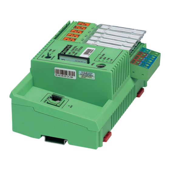
Description of the Inline Controller
General Description of the Inline Controller
Possible Fields of Application of the ILC 330 ETH, ILC 350 ETH and the ILC 350 ETH/M
Possible Fields of Application of the ILC 350 PN
Unpacking the Inline Controller
Connection and Operating Elements
Diagnostic and Status Indicators
Mode Selector Switch
Reset Button (Concealed)
Parameterization Memory
Using the Parameterization Memory
Inserting the Parameterization Memory
Parameterization Memory and Internet Explorer
Internet Explorer FTP Function
Activation/Deactivation of the FTP Server
Activation/Deactivation of the HTTP Server (ILC 330 ETH, ILC 350 ETH, ILC 350 ETH/M)
Internal Circuit Diagram
Mounting and Removing the Inline Controller
Communication Paths
Ethernet
Serial PRG Interface (Mini-DIN Female Connector)
Interbus
Local Bus
Remote Bus
Power Supply
Sizing of the Power Supply
Power Supply Connection
24 V Segment Supply / 24 V Main Supply
Segment Supply
24 V Main Voltage
24 V ILC Supply
Jumpers
Digital Inputs and Outputs
The Inline Controller under PC Worx
Software Version
IP Address
Setting the Real-Time Clock
Download Changes (ILC 330 ETH / ILC 350 ETH / ILC 350 ETH/M)
Function Blocks for Handling Files in the Parameterization Memory
File_Open
File_Close
File_Read
File_Write
File_Remove
File_Tell
File_Seek
File_Notify
Function Blocks for TCP/IP Communication
Ip_Connect
Ip_Usend
Ip_Urcv
Error Codes
System Variables and Status Information
System Variables
General Information
Status Register for Local Digital Inputs and Outputs
Status Register of an I/O Controller (Only ILC 350 PN)
INTERBUS Register of the ILC 350 PN
Diagnostic Status Register
Diagnostic Parameter Register
IEC 61131 Runtime System
Control Processor
Battery, Real-Time Clock, Memory Card
Power Supplies
Ethernet Status
Mode Selector Switch
System Time
Status Information of a PROFINET IO Device (Only ILC 350 PN)
Technical Data and Ordering Data
Technical Data
Ordering Data
Modules
Accessories
Software
Documentation
A Technical Appendix: Service and Maintenance
Error Causes and Remedies
Updating the Inline Controller Firmware
A 3 Connecting Unshielded Cables
B Index
Advertisement
Quick Links
1
Error Causes and Remedies
Download this manual
AUTOMATIONWORX
User Manual
UM EN ILC 330/350
Order No.: 2699370
Installing and Operating the ILC 330 ETH,
ILC 350 ETH, ILC 350 ETH/M and ILC 350 PN
Inline Controllers
Table of
Contents
Previous
Page
Next
Page
1
2
3
4
5
Advertisement
Table of Contents
Need help?
Do you have a question about the ILC 330 and is the answer not in the manual?
Ask a question
Questions and answers
Related Manuals for Phoenix Contact ILC 330
Controller Phoenix Contact ILC 131 STARTER KIT User Manual
User manual (92 pages)
Controller Phoenix Contact ILC 130 ETH User Manual
Inline controllers (78 pages)
Controller Phoenix Contact ILC 2050 BI User Manua
Inline controllers (76 pages)
Controller Phoenix Contact ILC 330 Series User Manual
(96 pages)
Controller Phoenix Contact ILC 350 Series User Manual
(96 pages)
Controller Phoenix Contact ILC 191 ME/AN Installing And Operating Information
Inline controllers (168 pages)
Controller Phoenix Contact ILC 350 ETH User Manual
Inline controllers (86 pages)
Controller Phoenix Contact ILC 350 PN User Manual
Inline controllers (86 pages)
Controller Phoenix Contact INTERBUS Quick Start Manual
(82 pages)
Controller Phoenix Contact IBS ABB DSC-T Diagnostics Manual
Ibs sys diag dsc um e interbus g4 (118 pages)
Controller Phoenix Contact EV Charge Control Basic User Manual
Charging controller (70 pages)
Controller Phoenix Contact MCR-FL-D-U-I-2SP-24 Manual
Process controller for current / voltage signals, with adding counter and 2 limits (63 pages)
Phoenix Contact AXC 1050, 2700988 - Controller Installation Notes For Electricians
(article)
Controller Phoenix Contact ELR W3 500AC I Series Manual
Hybrid motor starter with reversing function (56 pages)
Controller Phoenix Contact ELR H5-IES-SC-24DC/500AC-0,6 Manual
Hybrid motor starter with reversing function (56 pages)
Controller Phoenix Contact AXC 1050 User Manual
(162 pages)
This manual is also suitable for:
Ilc 350l
Ilc 330 eth
Ilc 350 eth
Ilc 350 eth/m
Ilc 350 pn
2737193
...
Show all
2737203
2985819
2876928
Table of Contents
Save PDF
Print
Rename the bookmark
Delete bookmark?
Delete from my manuals?
Login
Sign In
OR
Sign in with Facebook
Sign in with Google
Upload manual
Upload from disk
Upload from URL


Need help?
Do you have a question about the ILC 330 and is the answer not in the manual?
Questions and answers