Table of Contents
Advertisement
Quick Links
1. Product Description
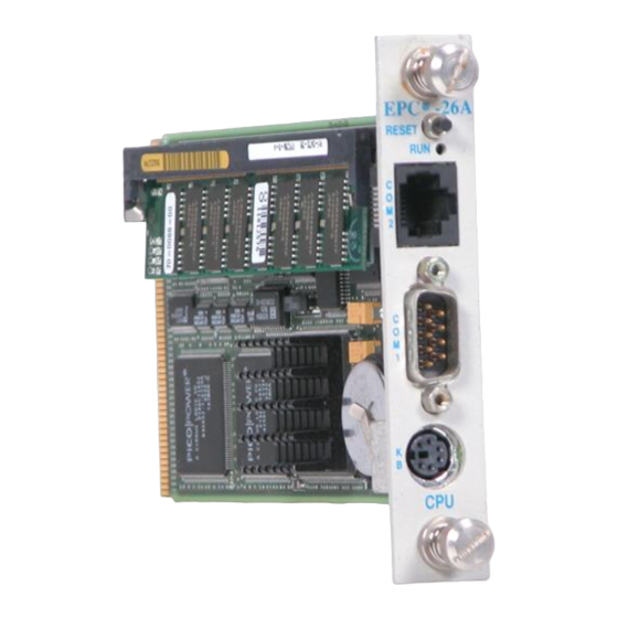
The EPC-26A/27 PC/AT-compatible CPU module is an EMC form factor EPC
based on the DX2 and DX4 Intel486 processor. The EPC-26A uses the 50
MHz Intel486 DX2 CPU, while the EPC-27 uses the 100 MHz IntelDX4.
The EPC-26A/27 uses the Pico-Power Redwood chip set, a two-chip set
packaged in a 176-pin TQFP.
This EPC meets stringent safety and low EMI standards (UL-1950). All front
panel accessible ports have filter networks for reduced EMI and increased
ESD protection.
The EPC-26A/27 processor modules contain the following features:
•
The EPC-26A contains an Intel DX2 Enhanced processor (208-pin
SQFP package, 3.3V). The EPC-27 is an Intel DX4 processor.
•
One 72-pin 3.3V SIMM socket for memory sizes of 4, 8, 16 or 32 MB
•
PC/AT compatible keyboard interface, reset switch and run LED
•
Standard PC-compatible peripherals
•
Time-of-day clock with 256 bytes of battery-backed CMOS RAM and
user-replaceable battery
•
One RS-232 9-pin DTE serial port (COM1) and one RJ45 serial port
(COM2)
•
Flashable Phoenix BIOS
•
EXM expansion interface
•
Optional 2 or 4 MB Flash memory and 128 KB SRAM and watchdog
timer
If your EPC-26A/27 contains the optional Flash/SRAM configuration, you will
also receive a File/Utilities diskette containing formatting software and SRAM
drivers. The software is explained in detail in the XFORMAT Software User's
Manual that accompanies the diskette.
1
Page 1
1
Advertisement
Table of Contents

Related Manuals for RadiSys EPC-26A/27


Summary of Contents for RadiSys EPC-26A/27
- Page 1 1. Product Description The EPC-26A/27 PC/AT-compatible CPU module is an EMC form factor EPC based on the DX2 and DX4 Intel486 processor. The EPC-26A uses the 50 MHz Intel486 DX2 CPU, while the EPC-27 uses the 100 MHz IntelDX4. The EPC-26A/27 uses the Pico-Power Redwood chip set, a two-chip set packaged in a 176-pin TQFP.
- Page 2 ® -26A/27 Hardware Reference ® RadiSys Corporation 15025 S.W. Koll Parkway Beaverton OR 97006 (503) 646-1800 FAX: (503) 646-1850 ________________________________________________________________ 07-0266-00 June 1995...
- Page 3 EPC-26A/27 Hardware Reference EPC and RadiSys are registered trademarks of RadiSys Corporation. IBM and PC/AT are trademarks of International Business Machines Corporation. Microsoft Windows and MS-DOS are registered trademarks of Microsoft Corporation. Intel and Intel486 are trademarks of Intel Corporation.
- Page 4 If an EPC product fails to operate in compliance with its specification during this period, RadiSys will, at its option, repair or replace the product at no charge. The customer is, however, responsible for shipping the product;...
- Page 5 EPC-26A/27 Hardware Reference NOTES Page iv...
-
Page 6: Table Of Contents
Keyboard Features Menu..............11 Advanced Menu ..................12 Integrated Peripherals Sub-Menu ............14 Memory Shadow Sub-Menu...............14 EXM Menu....................16 EXM Menu Entries for EPC-26A/27 ...........17 EXM Menu Entries for Additional EXMs..........17 Exit Menu ....................18 3. Theory of Operation..................21 Processor and Coprocessor ..............21 Memory ......................21 Memory Expansion..................22... - Page 7 EPC-26A/27 Hardware Reference 5. Troubleshooting & Error Messages ............31 Troubleshooting ..................31 Common Error Messages................32 6. Programming Interface ................39 Registers....................39 Configuration Registers............40 Addressing Registers .............. 40 Flash Data Access ..............41 SRAM data access ................41 Battery Low Condition................
-
Page 8: Specifications
EPC-26A/27 Hardware Reference Specifications The following table lists the environmental and electrical specifications of the EPC (with SIMM memory included). Environmental Temperature operating 0° to 60° C (* see below) storage -40° to 85° C 5 - 95% (non-condensing) Humidity... -
Page 9: Bios Configuration
2. BIOS Configuration Introduction The EPC-26A/27 uses the Phoenix BIOS. This section details the various menus and sub-menus that are used to configure the system. Your system may be pre-configured and require very little intervention. This section is written as though you are encountering each field in sequence and for the first time. -
Page 10: Bios Setup Screens
TAPPING OR HAMMERING ON IT BIOS Setup Screens The EPC-26A/27's BIOS contains a setup function to display and alter the system configuration. This information is maintained in the EPC-26A/27's nonvolatile CMOS RAM and is used by the BIOS to initialize the hardware in the EMC chassis. -
Page 11: Main Bios Setup Menu
This field identifies the type of floppy disk drive installed as the A drive. If the EPC-26A/27 has a floppy drive installed, the proper setting is usually for a 1.44 MB floppy disk drive. Other options include 360K, 720K, 1.2 MBytes, and 2.88 Mbytes. -
Page 12: Ide Adapter Sub-Menus
To use an EXM-HD or EXM-MX series mass storage unit, you must configure a master adapter; the slave is optional, and not relevant to most RadiSys hardware. To see the detailed characteristics of the device or to change the device, choose the IDE Adapter 0 Master Sub-Menu to configure the fixed disk. - Page 13 Use this option when setting up new disks. This option allows the BIOS to determine the proper settings of the disk based on information on the disk, which is detected by the EPC-26A/27 BIOS for drives that comply with ANSI specifications. Use the ENTER key to invoke this function.
- Page 14 EPC-26A/27 Hardware Reference Note that there are some restrictions when setting up devices on the EPC- 26A/27. If you plan to boot from a non-IDE device, such as the resident Flash memory, set the master drive as None and use the BIOS extension. You cannot boot from Flash and still have an IDE drive;...
-
Page 15: About Drive Letter Assignment
BIOS Configuration Boot Sequence: Use this option to define how the system treats floppy drive A: when booting. You can boot from a floppy in the A: drive or boot directly from the fixed disk drive. To reduce the amount of time required to boot, set the boot sequence to use the C: drive only. - Page 16 EPC-26A/27 Hardware Reference Setup Prompt: Use this option to enable or disable the message “Press F2 to enter Setup.” Even if the message is disabled, you can still press F2 to enter the Setup Menu. The default is to enable this prompt.
-
Page 17: Keyboard Features Menu
BIOS Configuration Keyboard Features Menu Use this sub-menu to enable or disable various keyboard features. PhoenixBIOS Setup Copyright 1992-94 Phoenix Technologies Ltd. Keyboard Features Item Specific Help Numlock [Auto] Key Click: [Disabled] Keyboard auto-repeat rate: [30/sec] Keyboard auto-repeat delay [1/2 sec] Help Select Item -/+ Change Values... -
Page 18: Advanced Menu
EPC-26A/27 Hardware Reference Keyboard auto-repeat delay: Use this option to set the delay between when a key is pressed and when the auto-repeat feature begins. Options are 1/4, 1/2, 3/4, and one second. When you are finished with this menu, press ESC to exit back to the main BIOS Setup Menu. -
Page 19: Memory Shadow Sub-Menu
BIOS Extension Base Address Flash ROMdisk: Use this option to enable Flash memory disks on the EPC-26A/27. This must be selected for the Flash memory to appear as a drive. The base address you select defines where the Flash ROMdisk BIOS extension is installed. - Page 20 EPC-26A/27 Hardware Reference Integrated Peripherals Sub-Menu Use the options in this sub-menu to enable or disable the COM ports. PhoenixBIOS Setup Copyright 1992-94 Phoenix Technologies Ltd. Integrated Peripherals Item Specific Help COM 1 [3F8, IRQ4] COM 2 [2F8, IRQ3] Help...
- Page 21 BIOS Configuration PhoenixBIOS Setup Copyright 1992-94 Phoenix Technologies Ltd. Memory Shadow Item Specific Help System Shadow: Enabled Video Shadow: [Enabled] Shadow Memory Regions: C800-CBFF: [Disabled] CC00-CFFF: [Disabled] D000-D3FF: [Disabled] D400-D7FF: [Disabled] D800-DBFF: [Disabled] DC00-DFFF: [Disabled] Help Select Item -/+ Change Values F9 Setup Defaults Exit Select Menu...
-
Page 22: Exm Menu
The EXM Setup Menu will support up to 12 EXM slots. The Setup Menu provides a selection for the number of available slots in a system. The selected number of slots is stored in CMOS. The EPC-26A/27 will configure the EXM bus according to the number of EXM slots selected. The default slot configuration is for 12 slots. -
Page 23: Exm Menu Entries For Epc-26A/27
OB1/OB2 of 00 00 indicating that no EXM is present EXM Menu Entries for EPC-26A/27 There are two possible entries for the EPC-26A/27, depending on whether the optional Flash/SRAM is present. These entries must be made for the exact slot the EPC-26A/27 occupies. - Page 24 Slots 0 through n Enter the configuration information for each remaining EXM expansion module to be installed. Note that while most EXM hardware reference manuals depict a different setup BIOS from the EPC-26A/27, the ID/OB1/OB2 information is valid. Page 18...
-
Page 25: Exit Menu
When using EXMs with configurable interrupts, DMA channels, I/O addresses, and/or memory addresses, avoid conflicts with built-in functions of the EPC-26A/27. Guidelines are: 1. If an interrupt is needed, use IRQ3, IRQ5, IRQ9, IRQ12, or IRQ15. IRQ7 can be used if a printer port is not being used. IRQ3 should not be used if the COM2 port is being used. - Page 26 EPC-26A/27 Hardware Reference Save Values and xit Use this option if you want to save the values you have just entered and exit in order to load the operating system. The new values are loaded, and you exit and reboot.
- Page 27 BIOS Configuration NOTES Page 21...
-
Page 28: Theory Of Operation
3. Theory of Operation The EPC-26A/27 is a PC/AT compatible processor module. The standard functions of the PC architecture are embodied in the PicoPower Redwood chip set. Processor and Coprocessor The EPC-27 uses the 100 MHz 208-pin, 3.3V Intel486 DX4 SL Enhanced CPU which contains an integrated math coprocessor. -
Page 29: Memory Expansion
EPC-26A/27 Hardware Reference Memory Expansion A single 72-pin SIMM socket is provided for memory expansion. A standard SIMM module is used for expansion, and must meet the following criteria: - 3.3 Volt - fast page mode - 72-pin - 70 nanosecond DRAM or better... -
Page 30: Rom And Rom Shadowing
Theory of Operation Note that since the EXM expansion interface has 24 address lines, some of the "mapped to EXM expansion interface" address areas map repeatedly, or wrap-around, in the expansion interface's address space. ROM and ROM Shadowing The EPC system BIOS is mapped into the top of the processor's 32-bit address space. The BIOS contains the PC BIOS, self-test functions, and the setup screen program. -
Page 31: Jumpers
Jumpers There are four jumpers on the EPC-26A/27 used primarily with the Flash formatting operation. The jumpers, which are located near the card edge and next to the SIMM socket, are show below. -
Page 32: Video Controllers
Front Panel LED The EPC-26A/27 has one green LED on the front panel. This RUN LED is lit whenever the EPC's DRAM memory is being accessed. It first comes on at power-up and should remain lit as long as the system is running. It is normal for the RUN LED to flicker during power-up. -
Page 33: Watchdog Timer
EPC-26A/27 Hardware Reference Software cannot distinguish this from a system with a separate EXM-2A card using the same configuration. A system cannot enable both the optional Flash/SRAM and an EXM-2A expansion module at the same time. Note that the XFORMAT program used to format flash memory is also distributed with the EXM-2 and EXM-2A expansion modules. -
Page 34: Resetting The Epc
Theory of Operation Resetting the EPC There are a number of ways to reset (reboot) the EPC. Power-off, Power-on This causes the entire system to reset. The system will run the power-on self-tests and reboot the operating system. Front-panel Reset button The Reset button causes the EPC to perform a hardware reset. - Page 35 EPC-26A/27 Hardware Reference NOTES Page 28...
-
Page 36: Connectors
EPC. Serial Ports There are two COM ports on the EPC-26A/27. The COM1 serial port is an RS-232 DB-9 DTE connector. It has the following drive capability: VO = -5V min @ 3K load to GND and VO = 5V min @ 3K load to GND. -
Page 37: Keyboard
EPC-26A/27 Hardware Reference COM2 is a DTE RJ45 phone jack and is defined in the following table: Signal Shield Ground Table 5. COM2 RJ45 Pin-out. Keyboard The keyboard connector is a 6-pin DIN defined below: Pin Signal Pin Signal Data... -
Page 38: Troubleshooting & Error Messages
5. Troubleshooting & Error Messages Troubleshooting This section deals with problems that you may encounter that do not provide an error message. If an error message is displayed, see the next section of this chapter, Common Error Messages. Symptoms Possible cause(s) Solution System appears to boot Video adapter not fully... -
Page 39: Common Error Messages
EPC-26A/27 Hardware Reference Symptoms Possible cause(s) Solution Serial port(s) do not work. Port is disabled in the Enter the Setup screen. Use cursor Setup screen. arrows to move to the appropriate field and toggle the entry to enable the port. - Page 40 Troubleshooting & Error Messages DISK BOOT FAILURE, INSERT SYSTEM DISK AND PRESS ENTER BIOS Problem: No boot disk could be found. Your hard disk may not have been partitioned into logical drive(s). PCs look for logical drives to boot from. Hard disks are physical drives; partitions are logical drives. Solution(s): If your BIOS setup screen has all disks disabled, or if your hard disk is disabled and no floppy diskette is inserted in the A: drive, run the BIOS setup program and verify that all disk parameters are correct.
- Page 41 EPC-26A/27 Hardware Reference EXM CONFIGURATION ERROR BIOS Problem: The EXMs installed (or not installed) do not match the configuration information in the BIOS setup EXM menu. Solution(s): Run the BIOS setup program. Enter the EXM menu. Verify the information listed on the screen, save any changes and reboot.
- Page 42 Troubleshooting & Error Messages KEYBOARD ERROR BIOS Problem: This message indicates that the system did not recognize a keyboard at power-up or you pressed a key during the power-on selftest. Solution(s): Check the integrity of the keyboard connector. If you think you pressed a key during power-up, reboot the system using the front panel reset button.
- Page 43 EPC-26A/27 Hardware Reference NON-SYSTEM DISK OR DISK ERROR BIOS REPLACE AND PRESS ANY KEY WHEN READY Problem: This is caused by an attempt to boot from a disk or diskette that is not recognized as a system disk; that is no system files exist on the disk or diskette.
- Page 44 Troubleshooting & Error Messages REAL TIME CLOCK ERROR - RUN SETUP BIOS Problem: The battery-backed TOD clock is incorrect. Solution(s): Run the BIOS setup program to determine what is wrong, and correct it. If the error occurs repeatedly, the EPC's battery has failed. Page 37...
- Page 45 EPC-26A/27 Hardware Reference NOTES Page 38...
-
Page 46: Programming Interface
This chapter contains information needed to write custom software drivers for the EPC’s Flash or SRAM. If using the supplied software that supports Flash or SRAM as a disk device, skip this chapter. The EPC-26A/27 defines the following registers in the I/O space. -
Page 47: Configuration Registers
26A/27’s EXM-2A interface does not implement the High address register (8386). The I/O address 8386 is reserved for future use. The EPC-26A/27’s EXM-2A interface provides a means of performing fast reads and writes of sequential bytes in the flash memory or SRAM. After each read or write access, the Low Address Register is incremented, allowing the next byte of data to be accessed without re-writing the address registers. -
Page 48: Flash Data Access
Address aliasing occurs when accessing the lower density SRAM chips. This may be used by software to determine the size of memory installed. The EPC-26A/27 uses a 128Kx8 chip SRAM chip; address aliasing begins at the 1MB boundary. Note that during power-down transition there is a very small probability that a single byte of SRAM or flash memory could be incorrectly written. -
Page 49: Sram Standard Memory Array
EPC-26A/27 Hardware Reference SRAM Standard Memory Array Typically, access to the SRAM is via a file system installed by the device driver SRAMDISK.SYS. For users who wish to bypass the file system and use the SRAM as a standard memory array, the following ANSI C routine is provided as an example of how to program an executable file. - Page 50 Programming Interface void writesection(UCHAR FAR *source, ULONG sramoffset) UCHAR ob; register USHORT rinductor; // Enable the card to allow register access outp(EXMID,Slot); ob = inp(0x102); outp(0x102,ob | EXMENABLE); // Load initial offset value (sramoffset should be // divisible by 256) outp(MSWHIGHBYTE,(USHORT) (sramoffset >>...
- Page 51 EPC-26A/27 Hardware Reference NOTES Page 44...
-
Page 52: Support And Service
Technical Support Services are designed for customers who have purchased their products from RadiSys or a sales representative. If your RadiSys product is part of a piece of OEM equipment, or was integrated by someone else as part of a system, support will be better provided by the OEM or system vendor that did the integration and understands the final product and environment. -
Page 53: Repair Services
EPC-26A/27 Hardware Reference Repair Services Factory Repair Service is provided for all RadiSys products. Standard service for all RadiSys products covers factory repair with customers paying shipping to the factory and RadiSys paying for return shipment. Overnight return shipment is available at customer expense. -
Page 54: Arranging Service
There is a minimum billing charge associated with this program. Arranging Service To schedule service for a product, please call RadiSys Technical Support directly at (503) 646-1800. Have the product model and serial numbers available, along with a description of the problem. A Technical Support representative will issue a Returned Materials Authorization (RMA) number, a code number by which we track the product while it is being processed. -
Page 55: Other Countries
Any ancillary information that might be helpful with the debugging process will be appreciated. Other Countries Contact the sales organization from which you purchased your RadiSys product for service and support. Page 48... -
Page 56: Appendix A: Mechanical Dimensions
Appendix A: Mechanical Dimensions Figure 8. EPC Mechanical Dimensions. Page A1... - Page 57 EPC-26A/27 Hardware Reference NOTES Page A2...
- Page 58 Appendix A: Mechanical Dimensions Figure 8. EPC Mechanical Dimensions. Page A1...
- Page 59 EPC-26A/27 Hardware Reference NOTES Page A2...
-
Page 60: Appendix B: Chip Set & I/O Map
Appendix B: Chip Set & I/O Map The following defines the I/O addresses decoded by the EPC. It does not define addresses that might be decoded by EXMs. First (8-bit) DMA controller: PicoPower Redwood chip set emulating 8237 of PC/AT I/O Addr Functional group Usage... - Page 61 EPC-26A/27 Hardware Reference Counter-Timer functions: PicoPower Redwood chip set emulating 8254 of PC/AT I/O Addr Functional group Usage Timer Counter 0 Counter 1 Counter 2 Control (W) Keyboard Port: PicoPower Redwood chip set emulating PC/AT I/O Addr Functional group Usage...
- Page 62 Appendix B: Chip Set & I/O Map Second Interrupt Controller: PicoPower Redwood chip set emulating 8259 of PC/AT I/O Addr Functional group Usage Interrupt controller 2 Port 0 Port 1 Second (16-bit) DMA Controller: PicoPower Redwood chip set emulating 8237 of PC/AT I/O Addr Functional group Usage...
- Page 63 EPC-26A/27 Hardware Reference Serial I/O (Com1) Port: PicoPower Redwood chip set emulates 16550 of PC/AT I/O Addr Functional group Usage COM1 serial port Receiver/transmitter buffer Baud rate divisor latch (LSB) Interrupt enable register Baud rate divisor latch (MSB) Interrupt ID register...
- Page 64 Appendix B: Chip Set & I/O Map Page B5...
-
Page 65: Appendix C: Interrupts And Dma Channels
Appendix C: Interrupts and DMA Channels Interrupts The assignment of interrupts for the EPC is shown in the following table: DRAM parity error, EXM expansion interface I/O channel check IRQ0 timer IRQ1 keyboard IRQ2 IRQ8 - IRQ15 cascade through IRQ2 IRQ3 COM2 serial port IRQ4... -
Page 66: Dma Channels
EPC-26A/27 Hardware Reference DMA Channels The assignment of DMA channels for the EPC is shown in the following table. 0 unassigned (8-bit) 1 unassigned (8-bit) 2 usually needed for floppy disk (8-bit) 3 unassigned 4 (Channel 0 - Channel 3 cascade through Channel 4) - Page 67 Appendix D: Creating Bootable Disks From Non-Bootable Drives In order to create a bootable disk image from a non-bootable drive, use the XFORMAT function with the /N flag. Refer to the example below: XFORMAT /N=6 /B=D: C:\FLASH This example assumes that the D: drive is a non-bootable device, such as a network drive or a RAM disk, and contains the necessary system files;...
- Page 68 EPC-27 Hardware Reference Refer to the Microsoft MS-DOS User Guide and Reference or use the online help by typing ATTRIB /? at the command line for more information about the ATTRIB command and various file attributes. It is a requirement for the IO.SYS and MSDOS.SYS files to be hidden, system, and read-only files in order for them to be bootable and/or safe from accidental damage.
- Page 69 Appendix E: Formatting Flash and SRAM Distribution Diskette Contents The distribution diskette contains the following files that are of interest when formatting Flash/SRAM: XFORMAT.EXE DOS-only flash formatting executable SRAMDISK.SYS SRAM device driver BB5.00 Boot block files for DOS 5.0 BB6.00 Boot block files for DOS 6.0, 6.1, &...
- Page 70 EPC-27 Hardware Reference Formatting Program The first task that you must perform before using the Flash/SRAM is format the flash memory and copy directories and files to it. This procedure is performed by the program named XFORMAT. It is distributed on the distribution diskette. This program formats both flash and SRAM.
- Page 71 Appendix E: Formattig Flash and SRAM /F<name> <size> File Output Flag. Outputs the disk image to the file <name> with size <size>. <size> is a hex value that specifies the number of Kbytes in the target file. This option is useful for creating VME memory disks and images for users that are going to write their own flash writing program, and is not strictly applicable to only the EXM-2A, but is documented here for completeness.
- Page 72 EPC-27 Hardware Reference System Flag. Creates a bootable disk image using the DOS system files on the disk that XFORMAT is invoked from. This operation fails if it cannot find the operating system files. This flag is for use with flash disks only. /T=<type>...
- Page 73 Appendix E: Formattig Flash and SRAM Format the flash memory in slot 0 using the system files and the boot block file BB6.00 from directory D:\ and copy all files from C:\FLASH. Note that you cannot simply copy a file to a flash disk. You must use XFORMAT to erase, format, and copy the contents of a directory to the flash disk.
- Page 74 DEVICE=C:\EPC\SRAMDISK.SYS /3 The path you insert depends on what directory you create when you copy the EXM-2A software from the RadiSys distribution diskette to your target drive. The SRAM driver can be loaded high to conserve conventional memory. Use the following line under DOS 6.X:...
- Page 75 Appendix E: Formattig Flash and SRAM Error Messages The following alphabetically listed error messages display during error conditions using XFORMAT.EXE or SRAMDISK.SYS. Error Message BATTERY NEEDS REPLACEMENT Explanation The XFORMAT program or the SRAMDISK.SYS driver have detected that the battery power is below 2.5V. Resolution Replace the battery.
- Page 76 EPC-27 Hardware Reference Error Message INVALID TARGET SIZE SPECIFIED Explanation An illegal character was detected in the file size portion of the /F parameter. Resolution Specify the file size using only hex characters. Error Message MORE THAN ONE SOURCE PATH WAS SPECIFIED Explanation Multiple source paths were detected on the command line.
- Page 77 Appendix E: Formattig Flash and SRAM Error Message SLOT NUMBER OUT OF RANGE Explanation The EXM slot number listed does not contain a flash/SRAM. Resolution Ensure that the EXM slot specified contains Flash/SRAM. Error Message SRAM FILE SYSTEMS ARE NOT BOOTABLE. DO NOT SPECIFY THE /S OR /B PARAMETERS Explanation XFORMAT does not create bootable SRAM disks.
- Page 78 EPC-27 Hardware Reference Any function or application other than XFORMAT that attempts to write to the flash disk will cause the system to lock up. Typical applications that write to disk might be Norton Utilities or PC Tools; typical DOS functions would be COPY, XCOPY, FORMAT, and FDISK.
- Page 79 Appendix F: Flash BIOS Updating Flash BIOS Updating The EPC supports flash BIOS updates for system BIOS. These updates are accomplished by running the NEW.BAT file, which contains the DOS executable NEWBIOS.EXE The Utilities diskette contains Flash formatting files in the root directory, and a subdirectory named using a 5-digit number to indicate the BIOS level included on the diskette.
- Page 80 EPC-27 Hardware Reference When in self-hosted mode, NEWBIOS uses a checksum to ensure that the BIOS is corrupted before proceeding. When running NEWBIOS as a remote download, the checksum step is bypassed. To display the usage model, type NEWBIOS and press <ENTER>. Available options include: NEWBIOS /F=<filelist>...
- Page 81 Appendix F: Flash BIOS Updating Insert the EPC’s BIOS update diskette in drive A. Switch the command line to drive A by typing A: and pressing <ENTER>. Display the contents of the NEW.BAT file by typing TYPE NEW.BAT and press <ENTER>. The first time you perform this step, the following default file contents display: NEWBIOS /F=FILL16.BIN...
- Page 82 Refer to the README.TXT file on the floppy for additional information. Note that you cannot use the NEWBIOS.EXE file on this Utilities diskette with any other RadiSys EPC, and you can only use NEWBIOS.EXE shipped on this EPC’s Utilities diskette on this EPC.
- Page 83 Index Flash ROMdisk installation, 13 floppy drive install, 5 3.3V operation, 21 floppy drive search, 10 72-pin SIMM socket, 22 IDE adapter sub-menus, 6 Integrated Peripherals sub- menu, 12, 14 key click, 11 abnormal conditions, 27 keyboard auto-repeat delay, About Drive Letter Assignment, 9 About Shadow Memory Regions, keyboard auto-repeat rate, 11 keyboard features sub-menu,...
- Page 84 EPC-24/26 Hardware Reference booting, 9 Com2, 1, 18, 29 connectors, 29 Flash memory setup in BIOS, 8 Flash ROM disk, 15 cooling requirements, 2 Flash ROMdisk, 12 CPU, 1, 21 Flash ROMdisk BIOS extension, flash write-protection jumper, 41 disk boot failure, 33 Flash/SRAM, 25, 40 DMA channels, 18, C2 EXM Menu entries, 17...
- Page 85 Index jumpers, 24 page frame, 22 Parallel port, 18 PARITY ERROR, 36 Phoenix BIOS, 1, 3 key click, 11 Pico-Power Redwood chip set, 1 Keyboard auto-repeat delay, 12 PicoPower Redwood chip set., 21 Keyboard auto-repeat rate, 11 Pin A57, 27 keyboard connector, 30 POST Errors, 10 keyboard errors, 35...
- Page 86 EPC-24/26 Hardware Reference fast reads and writes, 40 programming an executable file, 42 SRAM drivers, 1 SRAMDISK.SYS driver, 41, 42 standard memory array, 42 summary screen, 10 system BIOS mapping, 23 System Upper Memory, 22 Technical Support, 45 the PC architecture, 21 thumbscrews, 3 Time-of-day clock, 1 TOD clock, 23, 36, 37...
Need help?
Do you have a question about the EPC-26A/27 and is the answer not in the manual?
Questions and answers