
Related Manuals for RadiSys PROMENTUM ATCA-9100


Summary of Contents for RadiSys PROMENTUM ATCA-9100
- Page 1 (217) 352-9330 | Click HERE Find the RadiSys ATCA-9100 at our website:...
-
Page 2: Before You Begin
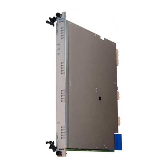
PROMENTUM® This document describes how to install and to set up the Promentum ATCA‐9100 Media Resource ® MEDIA RESOURCE MODULE Module (MRM). INSTALLATION GUIDE Before you begin To ensure all safety precautions are followed during ATCA-9100 installation and setup, review the Promentum Safety Information document on the ATCA‐9100 MRM downloads page at www.radisys.com/downloads. Obey ESD procedures Obey the electrostatic discharge (ESD) ARNING procedures described at www.radisys.com/esd when you install the product. Electrostatic discharge can cause permanent damage to static‐sensitive components in this product. Important ESD procedures include: • Keep the product in its ESD shielding bag until a step tells you to remove it. • Put on a grounded wrist strap before you move near or touch the product. • Install the product only in a grounded work area. Third edition, March 2011 *007-02584-0002* © 2006–2008, 2011 by RadiSys Corporation. All rights reserved. -
Page 3: Prepare For Installation
ATCA-9100 MRM Installation Guide Prepare for installation Installation of the MRM requires: • An AdvancedTCA (ATCA ) shelf, such as a RadiSys ATCA‐6000 or ATCA‐6006 shelf ® ® • Adequate ventilation for the shelf • Additional hardware to connect to the MRM from an external computer using one of these options: • Connect through a hub module in the shelf. This requires a standard crossover Ethernet cable. • Connect through a rear transition module (RTM). This requires a RadiSys rear debug card (order code TH‐1620‐00) or an RTM designed for the MRM. In addition, you need a crossover Ethernet cable or a null modem serial cable. Install the MRM This section assumes you are installing the module in an ATCA shelf and the shelf power is on. The ATCA shelf architecture lets you insert and remove the module from the shelf without powering down the system. 1. Obey ESD precautions and make sure you are adequately grounded before handling the module (see page 1). Opening the ejector handles 2. Remove the module from its antistatic bag. ... -
Page 4: Front Panel Led Indicators
Short blink = Preparing for removal Off = Normal operation DSP# LED3 DSP state Green = Application-defined Red = Application-defined or DSPs are initialized with no application loaded Install an RTM (optional) An RTM can be used to provide I/O access to the MRM. The RTM must be designed for compatibility with the MRM. RadiSys does not currently manufacture an RTM for use with the MRM. An RTM can be installed at any time. If you will use the RadiSys rear debug card instead of an RTM, see Install the rear debug card (optional). Preparation Before installing an RTM: Obey ESD precautions. See page 1 for more information. 2. Identify the front node slot where you installed the MRM. The RTM will be installed in the rear slot directly behind it. For example, if you installed the MRM in front slot 3, the RTM goes ... - Page 5 ATCA-9100 MRM Installation Guide Install the rear debug card (optional) In a lab environment, the RadiSys rear debug card can be used for I/O access as an alternative to an RTM. The MRM must be installed in the shelf before you install the rear debug card. To install the RadiSys rear debug card: Rear debug card 1. Use the instructions listed in Preparation on page 3. Serial 2. Make sure the MRM is already console installed. port 3. Remove the rear debug card from its antistatic bag. Ethernet 4. If you plan to use the Base Ethernet or maintenance Fabric Ethernet port, install an SFP port transceiver module into the corresponding socket. Both sockets support copper or optical Base gigabit Ethernet SFP transceivers. The ...
- Page 6 Connect to an external computer and the network Connect to an external computer and the network Connect to an external computer and the network using one of these methods: • Method 1: With an optional RTM designed to mate with the MRM or with the rear debug card • Method 2: Through another module via the backplane Ethernet interfaces Method 1: Connect with the RTM or rear debug card The MRM can be accessed by an external computer through the serial port and the Ethernet maintenance port on an RTM or rear debug card. Use the serial port to perform diagnostic and verification procedures. Use the Ethernet maintenance port to connect the MRM to the network and to perform configuration procedures. Connect to the serial port 1.
- Page 7 ATCA-9100 MRM Installation Guide 4. Log in as to get the prompt. From this prompt you can perform admin ATCA‐9100# configuration procedures. To log off the module at any time, enter command. exit Note: To connect to the Linux shell on the module, use either a serial port or a Telnet connection. After connecting, log in as and enter to view eth0 configuration root ifconfig settings. Method 2: Connect through another module via the backplane Ethernet interfaces If connecting with an RTM or rear debug card is not possible, you can access the MRM by connecting an external computer to another module in the shelf. To connect to the MRM through another module: 1. Find the hub module in the lower‐numbered hub slot. On the hub module, find an unused Ethernet port that connects to the Base interface. The diagram below illustrates the connection to the MRM when an ATCA‐2210 SCM is located in the lower‐numbered hub slot. Front Panel Base Port (e.g., 1/6) Base Ethernet Base Ethernet...
-
Page 8: View Port Status
Verify Ethernet switch operation 3. Configure the IP address of the external computer using the following: 10.2.<chassis>.<x>. The <chassis> parameter represents the shelf address (the physical location of the shelf within a central office). For the <x> variable, select a value from the range 17‐254 (for example, 10.2.<chassis>.17 to 10.2.<chassis>.254). Set the subnet mask for the interface to 255.255.0.0. 4. From the external computer use a Telnet connection to access the eth1:0 interface on the MRM. The static IP address is: 10.2.<chassis>.<slot>. The <chassis> parameter represents the shelf address, and the <slot> parameter represents the MRM’s location in the shelf. The ATCA‐9100 login prompt will display. If the prompt does not display, verify the Telnet connection to the IP address is correct. 5. Log in as to get the prompt. From this prompt you can perform admin ATCA‐9100# configuration procedures. To log off the MRM at any time, enter the command. exit 6. Disconnect the Ethernet cable from the Base Ethernet port on the hub module you connected through when you are done performing the configuration procedures. Verify Ethernet switch operation Use these steps to view port status and to enable ports on the Base Ethernet and Fabric Ethernet switches. View port status 1. Verify you are at this prompt. ATCA‐9100# If you are not at the appropriate prompt, see Connect to an external computer and the ... - Page 9 ATCA-9100 MRM Installation Guide 5. Enter the command to return to the prompt. exit ATCA‐9100# If you are asked to save changes, enter for yes or for no. If you choose for yes, this configuration will be saved as the startup configuration. 6. Enter the command to log off the module. exit Enable or disable specific ports Note: RadiSys recommends having only one backplane port enabled on the MRM Base interface if the shelf has two hub modules with interconnected Base switching domains. By default, RadiSys hub modules connect their Base switching domains. If the Fabric switching domains are also interconnected (which they are not by default on RadiSys hub modules), only one backplane port on the MRM Fabric interface should be enabled. 1. Verify you are at the applicable switch prompt. Switch Prompt Base Ethernet ATCA‐9100‐Base# Fabric Ethernet ATCA‐9100‐Fabric# If you are not at the appropriate prompt, see View port status on page 7 for instructions on how to get there.
- Page 10 Power up and load software to the DSP devices d. To enable another port, enter the command and perform the procedures described exit in steps b and c. When finished enabling ports, enter this series of commands to return to the prompt. ATCA‐9100# exit exit exit If you are asked to save changes, enter for yes or for no. If you choose for yes, this n y configuration will be saved as the startup configuration. 3. Enter the command again, to log off the module. exit Power up and load software to the DSP devices By default the DSP farms are powered off and no software is loaded on the DSP devices. The ...
-
Page 11: Where To Go From Here
Where to go from here See the ATCA‐9100 Media Resource Module Reference for detailed information on the module’s electrical and mechanical characteristics as well as the software specifically for controlling the DSPs. To configure other aspects of the MRM, see the Software Guide for Management Processors and General Purpose Computing Processors (also called the Software Guide) and the CLI Reference. You should also set passwords for the and the users and create user accounts for root admin those who do not require administrative privileges. See the Software Guide for more information. Where to get more product information Please visit the RadiSys Web site at www.radisys.com for product information and other resources. Downloads (manuals, release notes, software, etc.) are available at www.radisys.com/downloads. Artisan Technology Group - Quality Instrumentation ... Guaranteed | (888) 88-SOURCE | www.artisantg.com...
Need help?
Do you have a question about the PROMENTUM ATCA-9100 and is the answer not in the manual?
Questions and answers