
Subscribe to Our Youtube Channel
Related Manuals for RadiSys EPC-23


Summary of Contents for RadiSys EPC-23
- Page 1 (217) 352-9330 | Click HERE Find the RadiSys EPC-23 at our website:...
- Page 2 ® Hardware Reference ® RadiSys Corporation 15025 S.W. Koll Parkway Beaverton OR 97006 (503) 646-1800 FAX: (503) 646-1850 ______________________________________________________________________ 07-0161-01 July 1993 Artisan Scientific - Quality Instrumentation ... Guaranteed | (888) 88-SOURCE | www.artisan-scientific.com...
- Page 3 EPC-23 Hardware Reference EPC and RadiSys are registered trademarks of RadiSys Corporation. OS/2, IBM, and PC/AT are trademarks of International Business Machines Corporation. Microsoft Windows and MS-DOS are registered trademarks of Microsoft Corporation. Intel and Intel486 SL are trademarks of Intel Corporation.
- Page 4 If an EPC product fails to operate in compliance with its specification during this period, RadiSys will, at its option, repair or replace the product at no charge. The customer is, however, responsible for shipping the product; RadiSys assumes no responsibility for the product until it is received.
- Page 5 EPC-23 Hardware Reference NOTES Page iv Artisan Scientific - Quality Instrumentation ... Guaranteed | (888) 88-SOURCE | www.artisan-scientific.com...
-
Page 6: Table Of Contents
EPC-23 Hardware Reference Table of Contents 1. Product Description ....................1 Specifications ....................... 2 2. Installation and Configuration ................3 Insertion in an EXM Carrier ................3 Available Chassis....................4 Power-On Screen Display ..................5 BIOS Setup Screen ....................6 EXM Setup Screen .................... - Page 7 Figure 8. Battery Replacement................14 Figure 9. EPC-23 Mechanical Dimensions............A1 Tables Table 1. EPC-23 Environmental and Electrical Specifications ......2 Table 2. Fixed Disk Conversion Values ............... 11 Table 3. SIMM Organization for 0 MBytes Base Memory ........14 Table 4.
-
Page 8: Product Description
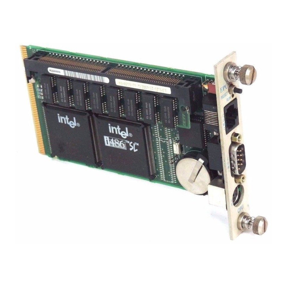
1. Product Description The EPC-23 is a PC/AT compatible CPU module in a very small form factor. Based on the Intel486 SL chip set, this EPC has been designed to meet stringent safety and low EMI standards (UL-1950). All front panel accessible ports have filter networks for reduced EMI and increased ESD protection. -
Page 9: Specifications
+5V @ 1.25 A typical +5V @ 1.1 A Table 1. EPC-23 Environmental and Electrical Specifications. * Upper temperature limit degrades 2° C per 1000 ft. elevation. Maximum elevation 10,000 ft. See Appendix A for mechanical dimensions. Page 2... -
Page 10: Installation And Configuration
EXM panel from the carrier (by unscrewing the thumbscrews) and insert the EPC-23 into the card guides. Firmly press the EPC-23 front panel to ensure that the module is properly seated in the subplane and secure it with the thumbscrews. -
Page 11: Available Chassis
O N L Y Figure 1. EMC-CH6D Chassis on an 8-Slot Backplane. The EPC-23 can be inserted into any slot in the chassis. Typically, the far left slot is selected. Note that the slot occupied by the EPC-23 has no unique configuration ID. - Page 12 Installation and Configuration Power-On Screen Display During the setup and configuration of the EPC-23, a graphics adapter and monitor are required. Whenever a hardware reset of the EPC occurs (power-on or front panel reset), the system performs a power-on self-test (POST). If not set for "quick boot," the POST displays information showing the status of the BIOS self-test if a monitor is attached via a video adapter.
-
Page 13: Power-On Screen Display
EPC-23 Hardware Reference BIOS Setup Screen The EPC-23 BIOS contains a setup function to display and alter the system configuration. This configuration information is maintained in the EPC's battery- backed CMOS RAM and is used by the BIOS to initialize the system hardware. - Page 14 EPC-23 Hardware Reference These values are changed by moving to them and typing in the format shown. Page 6 Artisan Scientific - Quality Instrumentation ... Guaranteed | (888) 88-SOURCE | www.artisan-scientific.com...
- Page 15 Installation and Configuration Configuration Errors This field provides several choices about the situations under which the BIOS should wait for user input if a configuration error is found. The selections are: 1) Halt on all errors 2) Ignore all errors 3) Ignore keyboard errors (allows operation without a keyboard) 4) Ignore disk errors 5) Ignore keyboard and disk errors...
-
Page 16: Exm Setup Screen
EMC-FDM in slots 6 and 7, and an EPC-23 in slot 0 might resemble the following: RadiSys EPC-23 EXM Setup, System BIOS V3.06 486SL, 4 MBytes memory Slot F10 = Save and return ESC = Return without saving ↑... - Page 17 Figure 5. EXM Slot Numbering. All slots not occupied by an EXM module show an ID of FF, indicating that no EXM is present. Note that the EPC-23 can be installed in any slot, and does not require any ID or option byte information.
-
Page 18: Fixed Disk Menu
Scroll through the numeric drive types to find the one matching the characteristics of the hard drive installed. Note that the RadiSys-supplied hard drive typically has a non-removable sticker listing the drive type number (or user-defined parameters, if necessary - refer to User-Definable Drive Types on page 11 for more information). -
Page 19: User-Definable Drive Types
Installation and Configuration User-Definable Drive Types If the correct AT disk type is not listed, the EPC provides user-editable drive types 48 →| and 49. Select either of these drive types. Use the TAB key ( )or the left and right ←... - Page 20 EPC-23 Hardware Reference NOTES Page 12 Artisan Scientific - Quality Instrumentation ... Guaranteed | (888) 88-SOURCE | www.artisan-scientific.com...
-
Page 21: Theory Of Operation
PC architecture are embodied in the Intel486 SL chip set. Processor and Coprocessor The EPC-23 uses the Intel486 SL CPU, which runs at 25 MHz and contains an integrated math coprocessor. Note that this is not a socketed part. Memory The EPC-23 can have a base memory configuration of 0 Mbytes or 4 Mbytes. -
Page 22: Memory Expansion
EPC-23 Hardware Reference Memory Expansion A single 72-pin SIMM socket is provided for memory expansion. SIMM memory occupies banks 0 or 1, depending on whether base memory occupies bank 0 or not. A standard SIMM module is used for memory expansion, or if 0 MBytes of base memory are present, as primary RAM. -
Page 23: Memory Map
Theory of Operation Memory Map The Intel486 SL supports a 25-bit physical memory address. Memory at addresses between 0 and the theoretical maximum of 20 MB (13FFFFFh) is mapped as follows: Range Content 0000000 - 009FFFF DRAM (first 640 KB) 00A0000 - 00BFFFF mapped to EXM expanison interface;... -
Page 24: Rom And Rom Shadowing
EPC-23 Hardware Reference ROM and ROM Shadowing The EPC contains a BIOS EPROM that is mapped into the top of the processor's 25-bit address space. The EPROM contains the PC BIOS, selftest functions, and the setup screen program. For best possible performance, the BIOS initialization software copies the ROM contents into DRAM (called shadowing) at addresses 0F0000-0FFFFF (also called the "F"... -
Page 25: Video Controllers
Front Panel LED The EPC-23 has one LED on the front panel. This RUN LED is lit whenever the EPC's memory is being accessed. It first comes on at power-up and should remain lit as long as the system is running. It is normal for the RUN LED to flicker during power-up. -
Page 26: Resetting The Epc
EPC-23 Hardware Reference Resetting the EPC There are a number of ways to reset (reboot) the EPC. Power-off, Power-on This causes the entire system to reset. The system will run the power-on self-tests and reboot the operating system. Front-panel Reset button The Reset button causes the EPC to perform a hardware reset. -
Page 27: Connectors
4. Connectors This chapter specifies the details of the connectors on the EPC-23. These connectors adhere to existing standards. Pins are labeled from the point of view of looking into the front of the connector on the EPC. Serial Ports... -
Page 28: Keyboard
EPC-23 Hardware Reference Keyboard The keyboard connector is a 6-pin DIN defined in the following table: Pin Signal Pin Signal Data not used Clock Ground not used Table 8. Keyboard Connector Pin-out. EXM Expansion Connector The EXM expansion connector on the rear of the EPC is a 116-pin cardedge connector. -
Page 29: Exm Expansion Connector Signals
Connectors B-Row: Signal Signal Signal Signal B16 GND B31 -SMEMW B45 SA12 (reserved) B17 IRQ9 B32 -SMEMR B46 (key) B18 IRQ6 B33 GND B47 (key) B19 IRQ4 B34 -MEMW B48 SA10 SD14 B20 IRQ3 B35 -MEMR B49 SA8 SD12 B21 -RSTDRV B36 BALE B50 GND SD10... - Page 30 EPC-23 Hardware Reference AEN (O) The 'address enable' signal is used to degate the microprocessor and other devices from the I/O channel to allow DMA transfers to take place. When this line is active, the DMA controller has control of the address bus, the data-bus Read command lines (memory and I/O), and the Write command lines (memory and I/O).
- Page 31 Connectors -EXTSMI (I) System management interrupt. Non-maskable. This is the highest priority interrupt even taking priority over NMI. See the Intel 486SL Programming Reference for details. This is an active low signal. -I/OCHK (I) The 'I/O channel check' signal provides the system board with parity (error) information about memory or devices on the I/O channel.
- Page 32 EPC-23 Hardware Reference IRQ3 through IRQ7, IRQ9, IRQ11, IRQ12, IRQ14, & IRQ15 (I) Interrupt requests 3 through 7, 9, 11, 12, 14, and 15 are used to signal the microprocessor that an I/O device needs attention. The interrupt requests are...
- Page 33 Connectors OSC (O) The 'oscillator' signal is a high-speed clock with a 70-nanosecond period (14.31818 MHz). This signal is not synchronous with the system clock. It has a 50% duty cycle. -REFRESH (I/O) This signal is used to indicate a refresh cycle and can be driven by a microprocessor on the I/O channel.
- Page 34 EPC-23 Hardware Reference SD0 through SD15 (I/O) These signals provide bus bits 0 through 15 for the microprocessor, memory, and I/O devices. D0 is the least-significant bit and D15 is the most-significant bit. All 8-bit devices on the I/O channel should use D0 through D7 for communications to the microprocessor.
-
Page 35: Troubleshooting & Error Messages
5. Troubleshooting & Error Messages Troubleshooting This section deals with problems that you may encounter that do not provide an error message. If an error message is displayed, see the next section of this chapter, Common Error Messages. Symptoms Possible cause(s) Solution System appears to boot Video adapter not fully... -
Page 36: Common Error Messages
EPC-23 Hardware Reference Symptoms Possible cause(s) Solution Serial port(s) do not work. Port is disabled in the Press CTRL+ALT+ESC to enter the Setup screen. Setup screen. Use cursor arrows to move to the appropriate field and toggle the entry to enable the port. - Page 37 Troubleshooting & Error Messages CMOS RAM ERROR, CHECK BATTERY / RUN SETUP BIOS Problem: Something in the CMOS RAM is incorrect. Solution(s): Run the BIOS setup program to determine what is wrong, and correct it. If the error occurs repeatedly, the EPC's battery has failed. DISK BOOT FAILURE, INSERT SYSTEM DISK AND PRESS ENTER BIOS Problem:...
- Page 38 EPC-23 Hardware Reference Problem: The IDE disk controller for drive C cannot be initialized. Solution(s): Ensure that the +5V power to the controller and hard disk are good and, if used, the ribbon cable to the hard disk is fully seated.
- Page 39 Troubleshooting & Error Messages Problem: You are trying to access a logical drive (e.g., A:, B:, ...) that is not known to the operating system. Solution(s): Select a different logical drive. If you are trying to access a hard disk, you may need to create the logical partition.
- Page 40 EPC-23 Hardware Reference MISSING OPERATING SYSTEM BIOS Problem: Although the system could read the hard disk and find the active partition, the operating system files could not be found. Solution(s): This can be caused by using a drive type number in the BIOS setup Fixed Disk menu that does not match the type number used to format the hard disk.
- Page 41 Troubleshooting & Error Messages PARITY ERROR IN SEGMENT ... Problem: This could be a software error (reading a nonexistent memory area) or a true hardware failure. Solution(s): Attempt to repeat the error. If the error occurs during the execution of your own proprietary software, verify that the memory location specified in your software is valid.
- Page 42 EPC-23 Hardware Reference NOTES Page 34 Artisan Scientific - Quality Instrumentation ... Guaranteed | (888) 88-SOURCE | www.artisan-scientific.com...
-
Page 43: Support And Service
Technical Support Services are designed for customers who have purchased their products from RadiSys or a sales representative. If your RadiSys product is part of a piece of OEM equipment, or was integrated by someone else as part of a system, support will be better provided by the OEM or system vendor that did the integration and understands the final product and environment. -
Page 44: Repair Services
EPC-23 Hardware Reference Repair Services Factory Repair Service is provided for all RadiSys products. Standard service for all RadiSys products covers factory repair with customers paying shipping to the factory and RadiSys paying for return shipment. Overnight return shipment is available at customer expense. -
Page 45: Arranging Service
There is a minimum billing charge associated with this program. Arranging Service To schedule service for a product, please call RadiSys Technical Support directly at (503) 646-1800. Have the product model and serial numbers available, along with a description of the problem. A Technical Support representative will issue a Returned Materials Authorization (RMA) number, a code number by which we track the product while it is being processed. -
Page 46: Other Countries
Any ancillary information that might be helpful with the debugging process will be appreciated. Other Countries Contact the sales organization from which you purchased your RadiSys product for service and support. Page 38 Artisan Scientific - Quality Instrumentation ... Guaranteed | (888) 88-SOURCE | www.artisan-scientific.com... -
Page 47: Appendix A: Mechanical Dimensions
Appendix A: Mechanical Dimensions 0.10 0.39 0.78 5.90 0.325 Figure 9. EPC-23 Mechanical Dimensions. Page A1 Artisan Scientific - Quality Instrumentation ... Guaranteed | (888) 88-SOURCE | www.artisan-scientific.com... - Page 48 EPC-23 Hardware Reference NOTES Page A2 Artisan Scientific - Quality Instrumentation ... Guaranteed | (888) 88-SOURCE | www.artisan-scientific.com...
Need help?
Do you have a question about the EPC-23 and is the answer not in the manual?
Questions and answers