RadiSys PROCELERANT CE915GM Quick Start Manual
Com express module
Hide thumbs
Also See for PROCELERANT CE915GM:
- Quick start manual (22 pages) ,
- Product manual (59 pages)

Related Manuals for RadiSys PROCELERANT CE915GM


Summary of Contents for RadiSys PROCELERANT CE915GM
- Page 1 PROCELERANT™ CE915GM COM EXPRESS MODULE QUICK START GUIDE CE760A-0 CE738A-0 CE373A-0 CE370A-0 CE738A-E-512 www.radisys.com 007-02531-0000 • April 2007...
- Page 2 Portions of this manual are copyrighted by the PCI Industrial Computer Manufacturers Group, and are reprinted with permission. RadiSys is a registered trademark and Procelerant is a trademark of RadiSys Corporation. PICMG is a registered trademark and COM Express is a trademark of the PCI Industrial Computer Manufacturers Group. Intel and Celeron are registered trademarks and Intel Core is a trademark of Intel Corporation.
-
Page 3: Table Of Contents
TABLE OF CONTENTS Preface ..........................About this guide..........................Where to get more information..................... Safety notices............................Lithium cell battery ..........................Electrostatic discharge ........................... Chapter 1: Checking your order................... COM Express module product codes................... CR100 carrier board product codes....................Optional components........................Memory modules........................... Fansinks .............................. - Page 4 Chapter 3: Identifying Key Components..............15 COM Express module layout......................CR100 carrier board layout......................Chapter 4: Assembling the Module and Carrier Board ..........Install the memory module......................Install the fansink..........................Install the module assembly on the carrier board..............24 Install the CR100 carrier board in the chassis ................26 Connect internal devices and set jumpers...................
-
Page 5: Preface
CR100 FlexATX carrier board was designed for this purpose, and is used as the sample carrier board in this guide. For detailed information and technical specifications, refer to the Procelerant CE915GM COM Express Module Product Manual available on the RadiSys Web site, www.radisys.com. -
Page 6: Electrostatic Discharge
Electrostatic discharge WARNING This product contains static-sensitive components and should be handled with care. Failure to employ adequate anti-static measures can cause irreparable damage to components. Electrostatic discharge (ESD) damage can result in partial or complete device failure, performance degradation, or reduced operating life. To avoid ESD damage, the following precautions are strongly recommended. -
Page 7: Chapter 1: Checking Your Order
The following table lists the CE915GM modules available at the time of publication. Check the CE915GM product page on the RadiSys Web site or contact your sales representative for the latest information about product offerings. Note that memory modules are not necessarily included and must be purchased separately. -
Page 8: Optional Components
Procelerant CE915GM Memory Validation List documentation on the RadiSys Web site. Fansinks The table below lists the product codes of fansinks offered by RadiSys. A complete list of all the components in each fansink kit is provided in the tables that follow. - Page 9 Optional components CE-AHSA package contents Product code Description Part number Backer plate 41x36mm, sheet metal (supplied with four M2 flat head 010-02709-00xx screws) CE-AHSA Aluminum active fansink, 125x94x42mm, 12V input 019-00352-00xx Carrier screws M2.5x0.45x4mm, pan head (used to tighten the carrier 09-0293-00xx board and module) Heatsink screws...
-
Page 10: Video Adapter
Checking your order CE-PHS17A package contents Product code Description Part number Backer plate 41x36mm, sheet metal (supplied with four M2 flat head 010-02709-00xx screws) CE-AHSA Aluminum active fansink, 125x95x17mm, 12V input 019-00352-00xx Carrier screws M2.5x0.45x4mm, pan head (used to tighten the carrier 09-0293-00xx board and module) Heatsink screws... -
Page 11: Chapter 2: Preparing Components And Accessories
PREPARING COMPONENTS AND ACCESSORIES Preparing COM Express components Lay out all the components on a grounded work surface as shown in Figure 1, “Basic component preparation,” on page 11 to prepare for assembly. Note that you may have different parts depending on what you ordered. Figure 1. -
Page 12: Power Supply
Preparing Components and Accessories Power supply The COM Express module will work with an ATX-compliant power supply or a power supply that is compliant with PICMG COM.0 COM Express Specification Revision 1.0. When selecting a power supply, be sure to consider the maximum power, AC input, frequency, input current, and DC out specifications of the power supply. -
Page 13: Video Devices
Video devices Video devices DVI and VGA Monitors The CR100-2DVI carrier board contains two DVI-I ports that comply with the Digital Video Interface (DVI) specification. Dual independent displays can be used with the appropriate drivers installed. Alternatively, you can attach a single analog VGA monitor to one of the DVI-I ports. - Page 14 Preparing Components and Accessories...
-
Page 15: Chapter 3: Identifying Key Components
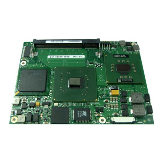
IDENTIFYING KEY COMPONENTS This chapter describes the key components and interfaces on the COM Express module and CR100 carrier board. COM Express module layout Figure 2 Figure 3 show the main components of COM Express modules. For features and functionality of these components, refer to the Product Manual. Figure 2. -
Page 16: Cr100 Carrier Board Layout
Identifying Key Components Figure 3. COM Express module bottom view Board-to-board interconnector CR100 carrier board layout For locations of key components on the CR100 carrier board, refer to the Procelerant CR100 FlexATX Carrier Board Product Manual. -
Page 17: Chapter 4: Assembling The Module And Carrier Board
ASSEMBLING THE MODULE AND CARRIER BOARD Install the memory module 1. Insert one memory module into the lower DDR2 SO-DIMM memory socket. Press down on the corners of the memory module until the latches click into place. Press firmly into place Memory module latches 2. -
Page 18: Install The Fansink
Assembling the Module and Carrier Board Install the fansink 1. Apply the Thermstrate TC phase-change material to the processor, GMCH, and ICH6-M chipsets. When assembled, heat from the chips will be conducted through the thermal interfaces to the fansink. 2. Install the heatsink spacer and module screw through the module as shown below. The screw will secure the fansink. - Page 19 Install the fansink 3. Check the bottom side of the fansink for correct alignment against the module. Against CPU Against mobile Intel 915GM For heatsink spacer Against Intel Express chipset and module screw ICH6-M...
- Page 20 Assembling the Module and Carrier Board 4. Place the fansink assembly on the module as shown, lining up the standoffs on the fansink with the screw holes in the module.
- Page 21 Install the fansink 5. Hold the module and fansink together and turn them over. Tighten the module screw to a torque value of 0.34 N·m (3 lbf·in). WARNING To avoid damaging the module, be careful not to overtighten the screws. Module screw...
- Page 22 Assembling the Module and Carrier Board 6. Place the heatsink backer plate on the module as shown. Tighten the supplied backer plate screws until they reach the PCB, and then back off 1/2 turn WARNING To avoid damaging the module, be careful not to overtighten the screws. M2 flat head backer plate screws Heatsink backer plate...
- Page 23 Install the fansink 7. Turn the assembly over again, and insert the five heatsink screws through their washers and into the holes at the locations shown. Heatsink screws and washers 8. The heatsink screws will protrude through the module. Use the five 5mm standoffs shown, and tighten the screws to a torque value of 0.34 N·m (3 lbf·in).
-
Page 24: Install The Module Assembly On The Carrier Board
Assembling the Module and Carrier Board 9. RadiSys recommends you place the assembly in a temperature chamber at a temperature of 60ºC for 10 minutes to allow the thermal interface material to phase change and conform to an optimal shape between the chips and fansink. - Page 25 Install the module assembly on the carrier board 2. Plug the fan’s 3-wire cable into the processor fan connector on the CR100 carrier board. 3. Insert the five carrier screws through the back of the CR100 carrier board at the locations shown, then tighten the screws to a torque value of 0.3136N·m (2.78 lbf·in).
-
Page 26: Install The Cr100 Carrier Board In The Chassis
1. Prepare a chassis designed to accept a standard FlexATX-sized board. 2. Remove any I/O shielding included with the chassis, and replace it with the CR100 carrier board’s I/O shielding from RadiSys. 3. Fit the module and carrier board assembly into the chassis and snap the carrier board’s rear I/O panel into the I/O shielding. - Page 27 Pins 1 and 2 open (default)—The system will boot from the COM Express module BIOS, ® which is based on the Phoenix FirstBIOS™ Notebook (Pro) BIOS with RadiSys extensions. • Pins 1 and 2 jumpered—The system will boot from the carrier board BIOS.
-
Page 28: Connect External I/O Devices And Chassis Components
Connect a digital video monitor to the primary DVI-I connector. • Connect a VGA monitor to the secondary DVI-I connector. If the VGA monitor cable has a DB15 connector, you will need a DVI-to-VGA adaptor as shown below (RadiSys product code CE-DVI-VGA). VGA side of adaptor DVI side of adaptor 3. -
Page 29: Power On The System
Power on the system Power on the system 1. If an LVDS flat panel is attached and requires an external power supply, power it up before powering up the system. Otherwise, the panel’s power supply will be provided by the CR100 carrier board via the backlight control connector. - Page 30 Assembling the Module and Carrier Board...
-
Page 31: Chapter 5: Installing Operating System And Drivers
Windows XP, Windows XP Embedded, and ® Red Hat Desktop (version 4.0 or later). Contact RadiSys to verify support of other operating systems. Install the operating system using a bootable CD-ROM. Follow the installation instructions provided with the operating system. - Page 32 Installing Operating System and Drivers...
Need help?
Do you have a question about the PROCELERANT CE915GM and is the answer not in the manual?
Questions and answers