
Related Manuals for Data Translation TEMPpoint DT9871U


Summary of Contents for Data Translation TEMPpoint DT9871U
- Page 1 Title Page UM-23654-D User’s Manual for USB Measurement Instruments (TEMPpoint , VOLTpoint and MEASURpoint...
- Page 2 Information furnished by Data Translation, Inc. is believed to be accurate and reliable; however, no responsibility is assumed by Data Translation, Inc. for its use; nor for any infringements of patents or other rights of third parties which may result from its use.
- Page 3 Changes or modifications to this equipment not expressly approved by Data Translation could void your authority to operate the equipment under Part 15 of the FCC Rules.
-
Page 5: Table Of Contents
Table of Contents Table of Contents About this Manual ............9 Intended Audience. - Page 6 Contents Connecting Voltage Inputs to Thermocouple Channels ......49 Connecting Voltage Inputs to RTD Channels ........50 Connecting Voltage Inputs to High Voltage Channels .
- Page 7 Contents Sample Clock Source ............91 Trigger Source .
- Page 8 Contents Appendix C: About ISO-Channel Technology ......123 ISO-Channel Technology............124 Why ISO-Channel Technology is Your Best Return on Investment .
-
Page 9: About This Manual
About this Manual TEMPpoint™ is a family of temperature measurement instruments that includes the DT9871U, DT9871, DT8871U, DT8871, DT9872, and DT8872. This manual describes the DT9871U, DT9871, and DT9872 USB models. VOLTpoint™ is a family of voltage measurement instruments that includes the DT9873 and DT8873. -
Page 10: Conventions Used In This Manual
About this Manual • Chapter “Setting Up and Installing the Instrument,” describes how to apply power to the instrument and connect the instrument to the network. • Chapter “Wiring Signals,” describes how to wire signals to the instrument. • Chapter “Verifying the Operation of Your Instrument,”... -
Page 11: Where To Get Help
RTD types, standards, and linearization. Where To Get Help Should you run into problems installing or using a TEMPpoint, VOLTpoint, or MEASURpoint instrument, the Data Translation Technical Support Department is available to provide technical assistance. Refer to Chapter 7 for more information. - Page 12 About this Manual...
-
Page 13: Chapter 1: Overview
Overview Hardware Features............Supported Software . -
Page 14: Hardware Features
Chapter 1 Hardware Features Data Translation provides a number of USB instruments to meet your measurement needs, including the following: • TEMPpoint – a family of temperature measurement instruments • VOLTpoint – a family of voltage measurement instruments • MEASURpoint – a family of mixed temperature and voltage measurement instruments All of these instruments support Version 2.0 and 1.1 of the USB bus. -
Page 15: Voltpoint Features
Overview • Throughput rate of up to 10 Samples/s for all channels. • Software or external, digital trigger on digital input line 0 starts acquisition • Auto-calibrating front-end resets the zero point on each power-up; in addition, the instrument supports anytime calibration, performing an auto-calibration function on software command •... -
Page 16: Measurpoint Features
Chapter 1 MEASURpoint Features The standard MEASURpoint (DT9874) instrument provides 16 thermocouple channels, 16 RTD channels, and 16 high voltage channels. The key features of MEASURpoint instruments are as follows: • Analog Input Channels 0 to 15: − Configurable channels for thermocouple or differential voltage inputs; easy-access jacks for each channel for quick wiring −... - Page 17 Overview • 8 opto-isolated digital input lines; you can read the digital input port through the analog input data stream for correlating analog and digital measurements • 8 opto-isolated digital output lines; the outputs are solid-state relays that operate from ±30 V at currents up to 400 mA (peak) AC or DC...
-
Page 18: Supported Software
In addition, this utility generates a report that lists the starting and ending calibration values for each channel, allowing traceability. Refer to the Data Translation web site (www.datatranslation.com) for information about selecting the right software package for your needs. -
Page 19: Accessories
Overview Accessories The following optional accessories are available for TEMPpoint, VOLTpoint, or MEASURpoint instruments: • STP37 screw terminal panel – The STP37 permits easy screw terminal connections for accessing the digital I/O signals of a TEMPpoint, VOLTpoint, or MEASURpoint instrument. •... -
Page 20: Getting Started Procedure
Chapter 1 Getting Started Procedure The flow diagram shown in Figure 1 illustrates the steps needed to get started using a TEMPpoint, VOLTpoint, or MEASURpoint instrument. This diagram is repeated in each Getting Started chapter; the shaded area in the diagram shows you where you are in the getting started procedure. -
Page 21: Part 1: Getting Started
Part 1: Getting Started... -
Page 23: Chapter 2: Preparing To Use The Instrument
Preparing to Use the Instrument Unpacking ..............Checking the System Requirements . - Page 24 Chapter 2 Prepare to Use the Instrument (this chapter) Set Up and Install the Instrument (see Chapter 3 starting on page Wire Signals (see Chapter 4 starting on page Verify the Operation of the Instrument (see Chapter 5 starting on page...
-
Page 25: Unpacking
• For DT9872, DT9874, and DT9874 instruments, a bag of pluggable screw terminable blocks and a screwdriver. If an item is missing or damaged, contact Data Translation. If you are in the United States, call the Customer Service Department at (508) 481-3700, ext. 1323. An application engineer will guide you through the appropriate steps for replacing missing or damaged items. -
Page 26: Checking The System Requirements
Chapter 2 Checking the System Requirements For reliable operation, your instrument requires the following: • PC with Pentium 233 MHz (or higher) processor • Windows XP, Windows Vista, or Windows 7 documentation. For USB Ver. 2.0 support, make sure that you install the appropriate Service Pack, if needed (version 2 for Windows XP). -
Page 27: Installing The Software
Preparing to Use the Instrument Installing the Software The Measurement Application, developed using Measure Foundry, provides a quick way to verify that your instrument is working properly. To install the Measurement Application and all the components necessary to use the Measurement Application with the instrument, including the IVI-COM driver, perform the following steps: 1. -
Page 28: Viewing The Documentation
• For documentation on the DtxMeasurement IVI-COM driver, click Programs -> IVI -> DtxMeasurement -> Documentation. • For documentation about Measure Foundry, click Programs -> Data Translation, Inc -> Measure Foundry -> 5.1. -> Measure Foundry User Manual The following may be helpful when using Adobe Reader: •... -
Page 29: Chapter 3: Setting Up And Installing The Instrument
Setting Up and Installing the Instrument Applying Power ............. . Attaching the Instrument to the Computer . - Page 30 Chapter 3 Prepare to Use the Instrument (see Chapter 2 starting on page Set Up and Install the Instrument (this chapter) Wire Signals (see Chapter 4 starting on page Verify the Operation of the Instrument (see Chapter 5 starting on page Note: Your TEMPpoint, VOLTpoint, and MEASURpoint instruments are factory-calibrated.
-
Page 31: Applying Power
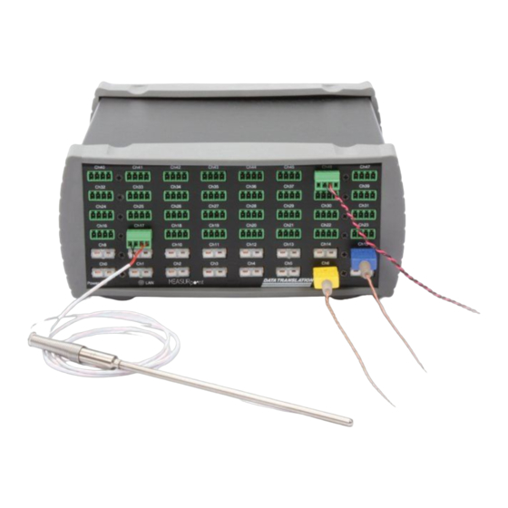
Setting Up and Installing the Instrument Applying Power TEMPpoint, VOLTpoint, and MEASURpoint instruments are shipped with an EP361 +5V power supply and cable. To apply power to the instrument, do the following: 1. Connect the +5 V power supply to the power connector on the rear panel of the instrument. - Page 32 Chapter 3 Power LED LAN LED (not used on this instrument) Figure 3: Front Panel of the Instrument...
-
Page 33: Attaching The Instrument To The Computer
Setting Up and Installing the Instrument Attaching the Instrument to the Computer This section describes how to attach a TEMPpoint, VOLTpoint, or MEASURpoint instrument to the host computer. Notes: Most computers have several USB ports that allow direct connection to USB devices. If your application requires more TEMPpoint, VOLTpoint, or MEASURpoint instruments than you have USB ports for, you can expand the number of USB devices attached to a single USB port by using expansion hubs. - Page 34 Chapter 3 +5 V Power Supply TEMPpoint, VOLTpoint, Host Computer or MEASURpoint USB Cables Instruments USB Ports +5 V Power Supply Figure 4: Attaching the Instrument to the Host Computer 4. Click Next and/or Finish in the wizard. Once the firmware is loaded, the wizard restarts to initiate the firmware to accept commands.
-
Page 35: Connecting To An Expansion Hub
Setting Up and Installing the Instrument 5. Repeat the steps to attach another TEMPpoint, VOLTpoint, or MEASURpoint instrument to the host computer, if desired. Connecting to an Expansion Hub Expansion hubs are powered by their own external power supply. Theoretically, you can connect up to five expansion hubs to a USB port on the host computer. - Page 36 Chapter 3 +5 V Power Supply +5 V Power Supply TEMPpoint, Cables TEMPpoint, VOLTpoint, or VOLTpoint, or MEASURpoint MEASURpoint Host Computer USB Cable USB Cable Power Supply Expansion Hubs for Hub Power Supply USB Cables for Hub TEMPpoint, TEMPpoint, VOLTpoint, or VOLTpoint, or MEASURpoint MEASURpoint...
-
Page 37: Configuring The Device Driver
Setting Up and Installing the Instrument Configuring the Device Driver To configure the device driver for a TEMPpoint, VOLTpoint, or MEASURpoint instrument, do the following: 1. If you have not already done so, power up the host computer and all peripherals. 2. - Page 38 Chapter 3...
-
Page 39: Chapter 4: Wiring Signals
Wiring Signals General Wiring Recommendations ..........Warm-Up Time . - Page 40 Chapter 4 Prepare to Use the Instrument (see Chapter 2 starting on page Set Up and Install the Instrument (see Chapter 3 starting on page Wire Signals (this chapter) Verify the Operation of the Instrument (see Chapter 5 starting on page...
-
Page 41: General Wiring Recommendations
Wiring Signals General Wiring Recommendations Keep the following recommendations in mind when wiring signals to a TEMPpoint, VOLTpoint, or MEASURpoint instrument: • Separate power and signal lines by using physically different wiring paths or conduits. • To avoid noise, do not locate the instrument and cabling next to sources that produce high electromagnetic fields, such as large electric motors, power lines, solenoids, and electric arcs, unless the signals are enclosed in a mumetal shield. -
Page 42: Warm-Up Time
Chapter 4 Warm-Up Time For accurate thermocouple measurements, DT9871U and DT9871 TEMPpoint instruments and thermocouple channels on the DT9874 MEASURpoint instruments require a warm-up time of 45 minutes for the analog circuitry to stabilize. For accurate high voltage measurements, the DT9873 VOLTpoint instruments and high voltage channels on the DT9874 MEASURpoint instruments require a warm-up time of 1 hour for the analog circuitry to stabilize. -
Page 43: Connecting Thermocouple Inputs
Wiring Signals Connecting Thermocouple Inputs The DT9871U, DT9871, and DT9874 instruments contain Cu-Cu thermocouple jacks for connecting thermocouple inputs. Note: On the standard DT9874 instrument, channels 0 to 15 correspond to the thermocouple input channels. Internally, these signals are connected in differential mode. You can mix and match the following thermocouple types across channels: B, E, J, K, N, R, S, and/or T. - Page 44 Chapter 4 Figure 7 shows how to connect a thermocouple input to a thermocouple channel. Thermocouple Channel Omega Cu-Cu Plug (SMPW-U-M Thermocouple Input Figure 7: Connecting Thermocouple Inputs...
-
Page 45: Connecting Rtd Inputs
Wiring Signals Connecting RTD Inputs Each DT9872 and DT9874 contains pluggable screw terminals for connecting RTD inputs. Note: On the standard DT9874 instrument, channels 16 to 31 correspond to the RTD input channels. Internally, these signals are connected in differential mode. Figure 8 shows the numbering of the screw terminal blocks for RTD connections. -
Page 46: 4-Wire Rtd Connections
Chapter 4 4-Wire RTD Connections The 4-wire configuration offers the best accuracy with long connection wires, compared to the 3- and 2-wire configurations. The 4-wire connection scheme eliminates errors due to lead wire ) and thermal heating. Wire impedance of up to 100 Ω anywhere in the hookup is resistance (R automatically cancelled as long as the sense wires are connected. -
Page 47: 2-Wire Rtd Connections
Wiring Signals RTD Channel μ Return Current – Sense +Sense is lead wire resistance. Figure 10: 3-Wire RTD Connection 2-Wire RTD Connections The 2-wire configuration is the least accurate of the RTD wiring configurations because the lead wire resistance (R ) and its variation with temperature contribute significant measurement errors, particularly if the lead wire is long. - Page 48 Chapter 4 RTD Channel μ Return Current – Sense +Sense Figure 11: 2-Wire RTD Connection...
-
Page 49: Connecting Voltage Inputs
Wiring Signals Connecting Voltage Inputs The way you connect voltage inputs depends on the channel type you are using. This section describes how to connect voltage inputs to thermocouple input channels, RTD input channels, and high voltage input channels. Connecting Voltage Inputs to Thermocouple Channels Figure 12 shows how to connect a differential voltage input to a thermocouple input channel on the DT9871U, DT9871, or DT9874 instrument. -
Page 50: Connecting Voltage Inputs To Rtd Channels
Chapter 4 Connecting Voltage Inputs to RTD Channels Figure 13 shows how to connect a voltage input to an RTD channel on a DT9872 or DT9874 instrument. Note: On the standard DT9874 instrument, channels 16 to 31 correspond to the RTD input channels. - Page 51 Wiring Signals Shield –Sense +Sense Connect Figure 14: Screw Terminal Block Numbering for High Voltage Connections Note: To make wiring easier, use the supplied screwdriver to attach your signals to the screw terminal block. When you are finished, plug the screw terminal block into the screw terminal header that corresponds to the channel to which you are wiring.
- Page 52 Chapter 4 The input impedance is well over 100 MΩ using the voltage –Sense and +Sense inputs. Note: For best accuracy when connecting voltage inputs, use twisted-pair wires with a dead-ended shield connected to pin 4 of the screw terminal block.
-
Page 53: Connecting Current Loop Inputs
Wiring Signals Connecting Current Loop Inputs In some applications, such as solar cell, fuel cell, and car battery testing applications, you may want to accurately sense and measure current in a high voltage loop. TEMPpoint, VOLTpoint, and MEASURpoint instruments provide channel-to-channel isolation of ±500 V, meaning that each input can be referenced to ±500 V. -
Page 54: Connecting Current Loop Inputs To Rtd Channels
Chapter 4 Thermocouple Channel – Ω series resistor 80 V Circuit+ – Ω Use a 1 series resistor to convert current to voltage. Ω For thermocouple channels on the DT9871U and DT9874, 1 = 0.075 A = 0.075 V. Ω For thermocouple channels on the DT9871, 1 = 1.25 A = 1.25 V. - Page 55 Wiring Signals RTD Channel – Sense +Sense Shield Ω shunt resistor 80 V Circuit+ – Ω Ω Use a 1 shunt resistor to convert current to voltage: 1 = 1.25 A = 1.25 V. Figure 17: Connecting Current Loop Inputs to RTD Channels...
-
Page 56: Connecting Current Loop Inputs To High Voltage Channels
Chapter 4 Connecting Current Loop Inputs to High Voltage Channels High voltage channels on the DT9873 and DT9874 instruments have an input range of ±10 V, ±100 V, or ±400 V. You select the input range for each channel using software. Note: On older versions of the instrument, the input range was fixed and depended on the model you purchased. - Page 57 Wiring Signals High Voltage Channel – Sense +Sense Shield Ω ±20 mA shunt resistor 28 V (can be up to ±500 V) Load – In this example, the input range is ±10 V. Figure 18: Connecting a Current Loop Input to a High Voltage Channel to Measure ±20 mA...
-
Page 58: Connecting Digital I/O Signals
Chapter 4 Connecting Digital I/O Signals To make digital I/O connections easier, you can use the optional STP37 screw terminal panel and EP333 cable with your TEMPpoint, VOLTpoint, or MEASURpoint instrument. Connect the STP37 to the digital I/O connector of the instrument as shown in Figure Instrument (Back Panel) -
Page 59: Connecting Digital Input Signals
Wiring Signals Digital Input 1+ Digital Output 7 − Digital Output 7 Digital Input 1 1 20 18 19 37 Digital Input 2+ Digital Output 6 − Digital Input 2 Digital Output 6 Digital Input 3+ Digital Output 5 − Digital Input 3 Digital Output 5 Digital Input 4+... -
Page 60: Connecting Digital Output Signals
Chapter 4 Connecting Digital Output Signals The digital output lines of a TEMPpoint, VOLTpoint, or MEASURpoint instrument act as solid-state relays. The customer-supplied signal can be ±30 V at up to 400 mA (peak) AC or You can use the digital output lines of the instrument to control solid-state or mechanical relays or high-current electric motors. -
Page 61: Chapter 5: Verifying The Operation Of Your Instrument
Verifying the Operation of Your Instrument Overview ..............Running the Measurement Application . - Page 62 Chapter 5 Prepare to Use the Instrument (see Chapter 2 starting on page Set Up and Install the Instrument (see Chapter 3 starting on page Wire Signals (see Chapter 4 starting on page Verify the Operation of the Instrument (this chapter)
-
Page 63: Overview
Verifying the Operation of Your Instrument Overview You can verify the operation of your TEMPpoint, VOLTpoint, or MEASURpoint instrument using the Measurement Application that is provided with the instrument. The Measurement Application, developed using Measure Foundry, lets you perform the following functions: •... -
Page 64: Running The Measurement Application
Chapter 5 Running the Measurement Application To run the Measurement Application, perform the following steps: 1. Click Start -> Programs -> Data Translation, Inc -> Measurement -> Measurement Application The Device Selection screen is displayed: 2. By default, the application "discovers" all TEMPpoint, VOLTpoint, and MEASURpoint instruments that are available and displays them in the list of Available Instruments. - Page 65 Verifying the Operation of Your Instrument − Device Simulation Mode - TEMPpoint RTD – Simulates the operation of a DT9872 or DT8872 TEMPpoint instrument. − Device Simulation Mode - TEMPpoint TC – Simulates the operation of a DT9871, DT9871U, DT8871, or DT8871U TEMPpoint instrument. When selected, the button indicator turns green.
- Page 66 Chapter 5 8. Click Continue. The latest state is saved and used when the application is next run, and the Channel Overview screen of the Measurement Application is displayed. Note that data acquisition is started automatically and temperature values are displayed (in degrees C), by default. Figure 23: Channel Overview Screen of the Measurement Application Note that the Channel Type field on the left of the screen indicates the type of sensor that is used for the corresponding row of measurement values.
-
Page 67: Changing The Configuration Of Your Instrument
Verifying the Operation of Your Instrument Changing the Configuration of Your Instrument To change the configuration of your instrument, follow these steps: 1. Stop acquisition by clicking the Start/Stop button from the main window or by clicking Stop Acquisition from the Acquisition menu. 2. - Page 68 Chapter 5 Note: If you want to set all the channels to the same configuration at once, select the configuration to apply using the Set all to combo box. If you select a voltage sensor type for a channel, the data is displayed in voltage. The sensor type setting is ignored for the digital input port.
-
Page 69: Defining Alarm Limits
Verifying the Operation of Your Instrument Defining Alarm Limits When you start the Measurement Application for the first time, the following alarm limits are defined for each channel: • Minimum alarm limit = 0 • Maximum alarm limit = 100 If the acquired value for a channel is between the defined minimum and maximum alarm limits, the value is within range and is displayed in black. - Page 70 Chapter 5 5. For each channel, select the digital output line (bit) that you want to turn on when the limits for a channel are exceeded. If you do not want to set a digital output line when the alarm limits are exceeded, choose none. Note: You can assign the same digital output line to multiple channels.
-
Page 71: Logging Data To Disk
Verifying the Operation of Your Instrument Logging Data to Disk To log data to disk, perform the following steps: 1. Ensure that you configured the channels that you want to log to disk (see page 68). 2. Start acquisition by clicking the Start/Stop button from the main window or, from the Acquisition menu, by selecting Start Acquisition. - Page 72 Chapter 5 7. To begin recording data, click the Start Recording button. You are prompted to name the file in which to store the recorded data. The data file has an .hpf extension. 8. Enter a name for the data file, and then click Save. The data for each channel is then displayed on the screen and logged to disk: 9.
-
Page 73: Viewing A Data File
Verifying the Operation of Your Instrument Viewing a Data File To view the data that you recorded in an .hpf file with the Chart Recorder, perform the following steps: 1. Click the Load Data File button from the main window, or from the File menu, select Load Data File. -
Page 74: Reading Digital Input Values
Chapter 5 Reading Digital Input Values To read the state of the digital input port, perform the following steps: 1. Click the Digital In button from the main window, or from the Windows menu, select Digital Input Panel, A screen similar to the following appears: Note: The LED indicator turns green when a value of 1 is detected on the digital input line and turns gray when a value of 0 is detected on the digital input line. -
Page 75: Exiting From The Measurement Application
Verifying the Operation of Your Instrument Exiting from the Measurement Application When you finished using the Measurement Application, exit from the application by selecting the File menu and clicking Quit. - Page 76 Chapter 5...
-
Page 77: Part 2: Using Your Instrument
Part 2: Using Your Instrument... -
Page 79: Chapter 6: Principles Of Operation
Principles of Operation Block Diagrams............. . . Analog Input Features . -
Page 80: Block Diagrams
Chapter 6 Block Diagrams This section includes the block diagrams for the DT9871U, DT9871, and DT9872 TEMPpoint instruments, DT9873 VOLTpoint instrument, and DT9874 MEASURpoint instruments. DT9871U Block Diagram Figure 24 shows the block diagram of the DT9871U TEMPpoint instrument. 1 of 8 +10 nA Break 64 kB Digital Input... -
Page 81: Dt9871 Block Diagram
Principles of Operation DT9871 Block Diagram Figure 25 shows the block diagram of the DT9871 instrument. 1 of 8 64 kB +100 nA Break Digital Input Isolated SRAM Detection Isolators DC-DC 1 of 8 Digital Output 24-Bit Isolators Control FPGA CJC Per Point 1 of up to 48 Channels... -
Page 82: Dt9872 Block Diagram
Chapter 6 DT9872 Block Diagram Figure 26 shows the block diagram of the DT9872 TEMPpoint instrument. 1 of 8 64 kB Digital Input +425 μA SRAM Isolated Isolators Current Source DC-DC 1 of 8 2.5 Hz Filter Digital Output Isolators 24-Bit Control FPGA... -
Page 83: Dt9873 Block Diagram
Principles of Operation DT9873 Block Diagram Figure 27 shows the block diagram of the DT9873 VOLTpoint instrument. 1 of 8 64 kB Digital Input Isolated SRAM Isolators DC-DC 2.5 Hz Filter 1 of 8 Ω 24-Bit Digital Output Isolators Control –... -
Page 84: Dt9874 Block Diagram
Chapter 6 DT9874 Block Diagram Figure 28 shows the block diagram of the DT9874 MEASURpoint instrument. 1 of 8 64 kB +10 nA Break Digital Input Isolated SRAM Detection Isolators DC-DC 1 of 8 Digital Output 24-Bit Isolators – CJC Per Point Channels 0 to 15 Power LED... -
Page 85: Analog Input Features
Principles of Operation Analog Input Features This section describes the following features of the analog input (A/D) subsystem on TEMPpoint, VOLTpoint, and MEASURpoint instruments: • Analog input channels, described on this page • Input ranges, described on page 88 • Resolution, described on page 90 •... -
Page 86: Thermocouple Input Channels
Chapter 6 Table 2: Number and Type of Analog Input Channels (cont.) # of Instrument Analog Input Type Models Channels Channel Types VOLTpoint DT9873-8 8 high voltage inputs (numbered 0 to 7) DT9873-16 16 high voltage inputs (numbered 0 to 15) DT9873-24 24 high voltage inputs (numbered 0 to 23) DT9873-32... -
Page 87: Cold Junction Compensation
Principles of Operation Table 3: Supported Measurement Range for Each Thermocouple Type Supported Measurement Range Thermocouple Type Minimum Maximum 0° C (32° F) 1820° C (3308° F) –200° C (–328° F) 1000° C (1832° F) –210° C (–346° F) 1200° C (2192° F) –200°... -
Page 88: Rtd Channels
Chapter 6 In addition, the software returns the value SENSOR_IS_OPEN (99999 decimal) for any channel that was configured for a thermocouple input and has either an open thermocouple or no thermocouple connected to it. This value is returned anytime a voltage greater than 100 mV is measure on the input, since this value is greater than any legitimate thermocouple voltage. -
Page 89: Out Of Range Data For Thermocouple Channels
Principles of Operation Table 4: Supported Input Ranges Instrument Type Models Input Range TEMPpoint DT9871U ±0.75 V for all channels DT9871 ±1.25 V for all channels DT9872 ±1.25 V for all channels VOLTpoint DT9873 ±10 V, ±100 V, or ±400 V (software-selectable for each channel) MEASURpoint DT9874-16T-16R-16V... -
Page 90: Out Of Range Data For Rtd Channels
Data Translation for recalibration. For information on factory recalibration, contact Data Translation at 508-481-3700, ext. 1323 (if you are in the USA) or call your local distributor (if you are located outside the USA); see our web site (www.datatranslation.com) -
Page 91: Sample Clock Source
Principles of Operation In addition, each instrument auto-calibrates on each power-up cycle to guarantee high-accuracy measurements. This process, also known as auto-zeroing, resets the zero point of each A/D. You can also auto-calibrate the instrument at any time (as long as acquisition is not in progress) using a software command. -
Page 92: Conversion Modes
Chapter 6 Conversion Modes TEMPpoint, VOLTpoint, and MEASURpoint instruments support continuous scan conversion modes for reading input measurements. Continuous scan mode takes full advantage of the capabilities of the TEMPpoint, VOLTpoint, and MEASURpoint instruments. Use continuous scan mode if you want to accurately control the period between successive simultaneous conversions of specific channels. -
Page 93: Filtering
Principles of Operation The FIFO on the instrument is used as a circular buffer. Acquisition continues indefinitely until you stop the operation. When the FIFO is full, the operation wraps to the beginning of the FIFO; values are overwritten starting at the first location in the FIFO. It is up to your application to retrieve the data from the FIFO;... -
Page 94: Data Format For Thermocouple Channels
Chapter 6 Data Format for Thermocouple Channels If you specify a thermocouple type of None for a thermocouple input channel, a voltage measurement is selected and the instrument returns a voltage value. For the DT9871U and DT9874 instruments, the value is in the range of ±0.075 V; for the DT9872 instrument, the value is in the range of ±1.25 V. - Page 95 Principles of Operation Additionally, the following constants may be reported to the host: • 99999.0 – SENSOR_IS_OPEN, described on page 87 • 88888.0 – TEMP_OUT_OF_RANGE_HIGH, described on page 89 page 90 • –88888.0 – TEMP_OUT_OF_RANGE_LOW, described on page 89 page 90 If any of these constants is reported, the A/D subsystem continues to acquire data;...
-
Page 96: Digital I/O Features
Chapter 6 Digital I/O Features TEMPpoint, VOLTpoint, and MEASURpoint instruments provide 8 digital input lines and 8 digital output lines that you can use to control external equipment, including solid-state or mechanical relays. This section describes the following digital I/O features: •... -
Page 97: Digital Output Lines
Principles of Operation Digital Output Lines TEMPpoint, VOLTpoint, and MEASURpoint instruments feature eight, latched and isolated digital output lines. The outputs are solid-state relays that operate at ±30 V and 400 mA peak (AC or DC). Switching time is 2 ms maximum. Figure 31 shows the digital output circuitry. - Page 98 Chapter 6...
-
Page 99: Chapter 7: Troubleshooting
Troubleshooting General Checklist ............Technical Support . -
Page 100: General Checklist
5. Check that you have wired your signals properly using the instructions in Chapter 6. Search the DT Knowledgebase in the Support section of the Data Translation web site (at www.datatranslation.com) for an answer to your problem. If you still experience problems, try using the information in... - Page 101 Calibration Utility, described on page 15, or return your instrument to Data Translation for recalibration. For information on factory recalibration, contact Data Translation at 508-481-3700, ext. 1323 (if you are in the USA) of call your local distributor (if you are located outside the USA);...
-
Page 102: Technical Support
Chapter 7 Technical Support If you have difficulty using your TEMPpoint, VOLTpoint, or MEASURpoint instrument, Data Translation’s Technical Support Department is available to provide technical assistance. To request technical support, go to our web site at http://www.datatranslation.com and click on the Support link. When requesting technical support, be prepared to provide the following information: •... -
Page 103: If Your Instrument Needs Factory Service
Troubleshooting If Your Instrument Needs Factory Service If your MEASURpoint instrument must be returned to Data Translation, do the following: 1. Record the instrument’s serial number, and then contact the Customer Service Department at (508) 481-3700, ext. 1323 (if you are in the USA) and obtain a Return Material Authorization (RMA). - Page 104 Chapter 7...
-
Page 105: Appendix A: Specifications
Specifications Basic Instrument Specifications ..........Thermocouple Specifications . -
Page 106: Basic Instrument Specifications
Appendix A Basic Instrument Specifications Table 7 lists the basic instrument specifications for TEMPpoint, VOLTpoint, and MEASURpoint instruments. Table 7: Basic Instrument Specifications Feature Specifications Number of channels in channel list Up to 48 analog input channels and one digital input port A/D converter type 24-bit Sigma-Delta... -
Page 107: Thermocouple Specifications
Specifications Thermocouple Specifications Table 8 lists the thermocouple specifications for thermocouple channels on the TEMPpoint and MEASURpoint instruments. Table 8: Thermocouple Specifications Feature Specifications Thermocouple types (software-selectable) B, E, J, K, N, R, S, T A/D resolution 24-bits Sample rate 10 Samples/s Thermal disturbance channel-to-channel None... -
Page 108: System Temperature Error For The Dt9871U And Dt9874
Appendix A System Temperature Error for the DT9871U and DT9874 Table 9 lists the accuracy of the DT9871U and DT9874 for each thermocouple type at several temperature points over the dynamic range of the instrument. Table 9: Calculated Thermocouple Accuracy of the DT9871U and DT9874 Thermocouple Type Input Temp. -
Page 109: System Temperature Error For The Dt9871
Specifications Figure 33: System Noise on the DT9871U and DT9874 Using the Moving Average Filter System Temperature Error for the DT9871 Table 10 lists the accuracy of the DT9871 for each thermocouple type at several temperature points over the dynamic range of the instrument. Table 10: Calculated Thermocouple Accuracy of the DT9871 Thermocouple Type Input... - Page 110 Appendix A The histograms shown in Figure 34 andFigure 35 characterize the Gaussian system noise distribution for each of the available filter types on the DT9871. Note that converting μV error to temperature error depends on thermocouple type. For example, a K thermocouple changes °...
-
Page 111: Rtd Specifications
Specifications RTD Specifications Table 11 lists the specifications for RTD channels on the TEMPpoint and MEASURpoint instruments. Table 11: RTD Specifications Feature Specifications Ω Ω Ω RTD types (software-selectable) Platinum 100 , 500 , and 1000 A/D converter resolution 24-bits Sample rate 10 Samples/s Supported temperature range... -
Page 112: Isolation And Protection Specifications
Appendix A Isolation and Protection Specifications Table 13 lists the isolation and protection specifications for the analog input subsystem on the TEMPpoint, VOLTpoint, and MEASURpoint instruments. Table 13: Isolation and Protection Specifications Feature Specifications Overvoltage protection (power on/off) DT9871U, DT9871, and DT9874 thermocouple channels: ±40 V DT9872 and DT9874 RTD channels: ±40 V... -
Page 113: Memory Specifications
Specifications Memory Specifications Table 14 lists the memory specifications for the analog input subsystem on the TEMPpoint, VOLTpoint, and MEASURpoint instruments. Table 14: Memory Specifications Feature Specifications Data memory onboard 4 MByte For Data logger built in, maximum time before old data is overwritten 48 channels @ 10 Hz: 30 minutes 48 channels @ 1 Hz:... -
Page 114: Temperature Stability Specifications
Appendix A Temperature Stability Specifications Table 15 lists the temperature stability specifications for thermocouple channels on the TEMPpoint and MEASURpoint instruments. Table 15: Temperature Stability Specifications for Thermocouple Channels Feature Specifications Additional error due to ambient temperature change J-type thermocouple: 0.010°... -
Page 115: Voltage Measurement Specifications
Specifications Voltage Measurement Specifications Table 17 lists the voltage measurement specifications for the TEMPpoint, VOLTpoint, and MEASURpoint instruments. Table 17: Voltage Measurement Specifications Feature Specifications Input voltage range (no compensation) DT9871U and DT9874 thermocouple channels: ±0.0750 V DT9871: ±1.2500 V DT9872 and DT9874 RTD channels: ±1.2500 V DT9873 and DT9874 high voltage channels:... - Page 116 Appendix A Table 17: Voltage Measurement Specifications (cont.) Feature Specifications System drift error, zero μ DT9871U and DT9874 thermocouple channels: ±0.02 V/° C typical μ DT9871: ±0.02 V/° C typical μ DT9872 and DT9874 RTD channels: ±0.10 V/° C μ DT9873 and DT9874 high voltage channels: ±0.5 V/°...
-
Page 117: Digital I/O Specifications
Specifications Digital I/O Specifications Table 18 lists the specifications for the digital input (DIN) and digital output (DOUT) subsystems on the TEMPpoint, VOLTpoint, and MEASURpoint instruments. Table 18: Digital I/O Specifications Feature Specifications Number of digital I/O lines 16 (8 In, 8 Out) Number of ports 2, 8-bit (1 In, 1 Out) Inputs... -
Page 118: Power, Physical, And Environmental Specifications
Appendix A Power, Physical, and Environmental Specifications Table 19 lists the power, physical, and environmental specifications for the TEMPpoint, VOLTpoint, and MEASURpoint instruments. Table 19: Power, Physical, and Environmental Specifications Feature Specifications USB power μ μ +5 V Standby: A maximum (360 A typical) +5 V Power On: 2 mA maximum (1 mA typical) -
Page 119: Regulatory Specifications
Specifications Regulatory Specifications Table 20 lists the regulatory specifications for the TEMPpoint, VOLTpoint, and MEASURpoint instruments. Table 20: Regulatory Specifications Feature Specifications Emissions (EMI) FCC Part 15, EN55022:1994 + A1:1995 + A2:1997 VCCI, AS/NZS 3548 Class A Immunity EN61000-6-1:2001 RoHS (EU Directive 2002/95/EG) Compliant (as of July 1st, 2006) Aerospace Material Specification Compliant with AMS2750D... -
Page 120: Connector Specifications
Appendix A Connector Specifications This section lists the specifications for the following connector types: • Thermocouple connectors • RTD connectors • High Voltage connectors Thermocouple Connectors Table 21 lists the specifications for the thermocouple connectors used on the TEMPpoint and MEASURpoint instruments. -
Page 121: Appendix B: Connector Pin Assignments
Connector Pin Assignments... - Page 122 Appendix B Table 24 lists the pin assignments for the 37-pin digital I/O connector on TEMPpoint, VOLTpoint, and MEASURpoint instruments. Table 24: Digital I/O Connector Pin Assignments Description Description Digital Input 0+ – Digital Input 1+ Digital Input 0– Digital Input 2+ Digital Input 1–...
-
Page 123: Appendix C: About Iso-Channel Technology
About ISO-Channel Technology ISO-Channel Technology............Why ISO-Channel Technology is Your Best Return On Investment. -
Page 124: Iso-Channel Technology
Appendix C ISO-Channel Technology All TEMPpoint, VOLTpoint, and MEASURpoint products use ISO-Channel™ technology to eliminate common mode noise and ground loop problems. This appendix includes two white papers that describe the benefits of using ISO-Channel technology. -
Page 125: Why Iso-Channel Technology Is Your Best Return On Investment
About ISO-Channel Technology Why ISO-Channel Technology is Your Best Return on Investment When connecting signal sources to an instrument, it is important to eliminate the sources of error that can contribute to inaccuracies in your measurements. In most measurement instruments, this burden is on the customer. Instruments that use ISO-Channel technology, however, solve this problem for you –... -
Page 126: Iso-Channel Eliminates Ground Loops And Increases Common-Mode Rejection
Appendix C ISO-Channel Eliminates Ground Loops and Increases Common-Mode Rejection ISO-Channel technology eliminates ground loop problems by using a differential, isolated, floating front-end. As you can see in Figure 37, a floating voltage signal is not referenced to system ground. Figure 37: Floating Signals To measure floating signal sources, ISO-Channel technology uses differential analog input signals, a 24-bit Delta-Sigma A/D converter for each channel, and channel-to-channel... -
Page 127: Floating, Differential Signals
About ISO-Channel Technology Figure 38: ISO-Channel Technology Floating, Differential Signals ISO-Channel technology implements a virtually ideal differential measurement system that reads only the potential difference between the positive and negative terminals of the amplifier. For each channel, the differential signals are isolated in that they are referenced to a ground reference point that is not connected to earth ground. -
Page 128: Simultaneous Architecture
Appendix C Figure 39: Differential Signals and Common-Mode Voltage When the measurement instrument and signal source are at different ground potentials, the difference in potential is called common-mode voltage. The measurement instrument cannot discern between the signal and the common-mode voltage believing that the sum of these voltages is the actual signal. -
Page 129: Channel-To-Channel Isolation
About ISO-Channel Technology Figure 40: Simultaneous vs. Multiplexed Architectures Channel-to-Channel Isolation Besides differential inputs, floating channels, and a simultaneous architecture, ISO-Channel technology provides channel-to-channel isolation, not just isolation from the analog front-end to the computer ground. With this kind of isolation, the channels are individually isolated from each other and from other system components. -
Page 130: Summary
Appendix C Summary ISO-Channel technology offers built in system redundancy to protect your investment - if one channel fails, the remaining channels are completely unaffected! Instruments with ISO-Channel technology also adapt to the sensors that they are connected to, allowing a different ground reference for each signal without introducing errors! For these key reasons, ISO-Channel technology protects against problems in the field, and thereby, reduces costs –... -
Page 131: Floating Signal Inputs Offer New Application Advantages
About ISO-Channel Technology Floating Signal Inputs Offer New Application Advantages Precision measurement systems are often limited in that all inputs are connected to a single ground. Typically, multiplexer input configurations are set up this way, since all signal inputs are connected to the same return. Even differential input configurations use the same ground reference. -
Page 132: Isolating Each Input
Appendix C Figure 42: Even when using an A/D per channel, noise can contribute errors to your measurement results. To minimize noise and ground loops, some newer systems offer isolation between the input signal ground reference and the computer ground. This effectively separates the computer ground from the measurement portion of the system. - Page 133 About ISO-Channel Technology Figure 43: Common mode voltage is present when different ground potentials exist in your measurement system. In many applications, noise is a fact and a common occurrence. To prevent this noise from entering the signal path, the signal must be isolated on a channel-to-channel basis as well as from the PC ground reference.
- Page 134 Appendix C Figure 44: An A/D per channel and a DC-to-DC converter for each A/D provides channel-to-channel isolation, where each signal can float to its own ground reference. Input channel return references are effectively separate instruments when the inputs are isolated.
-
Page 135: New Application Derived From Isolated Channels
About ISO-Channel Technology Figure 45: When measuring two input signals with channel-to-channel isolation, three ground references are provided (signal 0, signal 1, and PC ground). New Application Derived from Isolated Channels A typical application of measuring 48 channels of varying voltages from sensors, such as batteries, thermocouples, RTDs pressure sensors, etc., often must use different instruments because of the various ranges needed. -
Page 136: Summary
Appendix C Figure 46: Because each floating signal input is isolated from each other, you can use two separate channels, normally each configured for ±10V, to measure a ±20V signal. Simply sum the result of each channel to get your result. Summary When you need the highest accuracy and the most flexibility from your measurement system, ensure that floating signal inputs are provided. -
Page 137: Index
Index Index voltage inputs to high voltage channels voltage inputs to RTD channels accessories voltage inputs to thermocouple channels accuracy specifications, thermocouple applying power alpha curves attaching the instrument to the computer analog input basic instrument specifications calibration channels block diagrams CJC circuit DT8871 conversion modes... - Page 138 Index data encoding input ranges data format installing the software high voltage channels ISO-Channel technology RTD channels isolation thermocouple channels isolation specifications device driver IVI-COM driver differential channels digital I/O channel-to-channel isolation LEDs connecting input signals connecting output signals lines Power operation modes reading the digital input port in the analog data...
- Page 139 Index RTD channels memory thermocouple channels physical power regulatory physical specifications RTD connectors power system temperature error applying temperature stability specifications thermocouple Power LED thermocouple connectors protection specifications voltage connectors voltage measurement STP37 screw terminal panel system requirements rack mounting system temperature error raw filter recommendations for wiring...
- Page 140 Index current loop inputs to thermocouple channels digital inputs digital outputs recommendations RTD inputs thermocouple inputs voltage inputs to high voltage channels voltage inputs to RTD channels voltage inputs to thermocouple channels warm-up time...
Need help?
Do you have a question about the TEMPpoint DT9871U and is the answer not in the manual?
Questions and answers