Table of Contents
Advertisement
Quick Links
Advertisement
Table of Contents

Related Manuals for Data Translation DT9837A


Summary of Contents for Data Translation DT9837A
- Page 1 Title Page UM-22417-AJ DT9837 Series User’s Manual...
- Page 2 Information furnished by Data Translation, Inc. is believed to be accurate and reliable; however, no responsibility is assumed by Data Translation, Inc. for its use; nor for any infringements of patents or other rights of third parties which may result from its use.
- Page 3 Changes or modifications to this equipment not expressly approved by Data Translation could void your authority to operate the equipment under Part 15 of the FCC Rules.
-
Page 5: Table Of Contents
Key Features of the DT9837A ........ - Page 6 (DT9837A Only) ........
- Page 7 Triggering Acquisition on Multiple Modules ........86 Synchronizing Acquisition on Multiple DT9837A, DT9837B, or DT9837C Modules ..87 Chapter 6: Supported Device Driver Capabilities.
- Page 8 Writing to EEPROM to Change the High Power Mode ......138 DT9837A, DT9837B, and DT9837C Register-Level Programming ....140 Writing to the General Control Register 4 .
-
Page 9: About This Manual
About this Manual The DT9837 Series includes the DT9837, DT9837A, DT9837B, and DT9837C modules. The first part of this manual describes how to install and set up your DT9837 Series module and device driver, and verify that your module is working properly. -
Page 10: Conventions Used In This Manual
Refer to the following documents for more information on using the DT9837 Series modules: • Benefits of the Universal Serial Bus for Data Acquisition. This white paper describes why USB is an attractive alternative for data acquisition. It is available on the Data Translation web site (www.datatranslation.com). -
Page 11: Where To Get Help
About this Manual Where To Get Help Should you run into problems installing or using a DT9837 Series module, the Data Translation Technical Support Department is available to provide technical assistance. Refer Chapter 7 for more information. If you are outside the United States or Canada, call your local distributor, whose number is listed on our web site (www.datatranslation.com). - Page 12 About this Manual...
-
Page 13: Chapter 1: Overview
Overview Hardware Features............Supported Software . -
Page 14: Hardware Features
For the start trigger on the DT9837, the threshold channel is channel 0 and the threshold level is fixed at 1.0 V. For the start trigger on the DT9837A and DT9837B, the threshold channel is channel 0 and the analog threshold level is programmable from 0.2 V to 9.8 V with 0.1 V of hysteresis. -
Page 15: Key Features Of The Dt9837
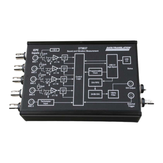
Overview Key Features of the DT9837 Figure 1 shows the layout of the DT9837 module. Figure 1: DT9837 Module The key features of the DT9837 module are as follows: • Simultaneous analog input and waveform analog output operations • Analog input subsystem: −... -
Page 16: Key Features Of The Dt9837A
Figure 2 shows the layout of the DT9837A module. Figure 2: DT9837A Module The key hardware features of the DT9837A module are as follows: • Simultaneous analog input and analog output operations (continuous or waveform mode) • Analog input subsystem: −... - Page 17 − Optional OEM version of this module, called the DT9837A-OEM, supports the ability to read the value of gate counter 2 in the analog input data stream, allowing you to precisely correlate gate input measurements with analog input measurements −...
-
Page 18: Key Features Of The Dt9837B
Chapter 1 Key Features of the DT9837B Figure 3 shows the layout of the DT9837B module. Figure 3: DT9837B Module The key hardware features of the DT9837B module are as follows: • Four, simultaneous 24-bit A/D converters • Internal clock source with a throughput rate up to 105.469 kSamples/s for simultaneous, high-resolution analog input measurements •... -
Page 19: Key Features Of The Dt9837C
Overview • Supports a start trigger for acquiring pre-trigger samples and a reference trigger for acquiring post-trigger samples. You can specify the number of post-trigger samples to acquire before stopping the operation. • For the start trigger, supports a software-programmable trigger source (software, external digital trigger, or a positive-going analog threshold trigger on analog input channel 0). - Page 20 Chapter 1 The key hardware features of the DT9837C module are as follows: • Simultaneous analog input and analog output operations (continuous or waveform mode) • Mini-XLR connectors (on the DT9837C-XLR) or BNC connectors (on the DT9837C-BNC) for connecting audio inputs •...
-
Page 21: Supported Software
• DT9837 Series Device Drivers – Two device drivers are provided in the DT9837 Series: one for the DT9837 module and one for the DT9837A, DT9837B, and DT9837C modules. The DT9837 Series Device Drivers allow you to use a DT9837, DT9837A, DT9837B, or DT9837C module with any of the supported software packages or utilities. - Page 22 Chapter 1 • QuickDAQ FFT Analysis Option – When enabled with a purchased license key, the QuickDAQ FFT Analysis option includes all the features of the QuickDAQ Base version with the FFT Analysis option plus basic FFT analysis features, including the following: −...
- Page 23 Windows Vista, Windows 7, or Windows 8; the DataAcq SDK complies with the DT-Open Layers standard. • DAQ Adaptor for MATLAB – Data Translation’s DAQ Adaptor provides an interface between the MATLAB Data Acquisition (DAQ) subsystem from The MathWorks and Data Translation’s DT-Open Layers architecture.
-
Page 24: Supported Accessories
Note: You must have revision H or later of the DT9837A module or revision F or later of the DT9837A-OEM module to be able to attach four modules together. You can identify the revision of your module by looking at the serial number label on your module. -
Page 25: Getting Started Procedure
Overview Getting Started Procedure The flow diagram shown in Figure 6 illustrates the steps needed to get started using a DT9837 Series module. This diagram is repeated in each Getting Started chapter; the shaded area in the diagram shows you where you are in the getting started procedure. Set Up and Install the Module (see Chapter 2... - Page 26 Chapter 1...
-
Page 27: Part 1: Getting Started
Part 1: Getting Started... -
Page 29: Chapter 2: Setting Up And Installing The Module
Setting Up and Installing the Module Unpacking ..............System Requirements . - Page 30 Chapter 2 Set Up and Install the Module (this chapter) Wire Signals (see Chapter 3 starting on page Verify the Operation of the Module (see Chapter 4 starting on page...
-
Page 31: Unpacking
• EP365 USB cable • Data Acquisition OMNI CD-ROM If an item is missing or damaged, contact Data Translation. If you are in the United States, call the Customer Service Department at (508) 481-3700, ext. 1323. An application engineer will guide you through the appropriate steps for replacing missing or damaged items. -
Page 32: System Requirements
Chapter 2 System Requirements For reliable operation, ensure that your computer meets the following system requirements: • Processor: Pentium 4/M or equivalent • RAM: 1 GB • Screen Resolution: 1024 x 768 pixels • Operating System: Windows 8, Windows 7, Windows Vista (32- and 64-bit) •... -
Page 33: Attaching Modules To The Computer
Setting Up and Installing the Module Attaching Modules to the Computer This section describes how to attach a DT9837 Series module to the host computer. Note: Most computers have several USB ports that allow direct connection to USB devices. If your application requires more DT9837 Series modules than you have USB ports for, you can expand the number of USB devices attached to a single USB port by using expansion hubs. -
Page 34: Connecting To An Expansion Hub
Chapter 2 3. For Windows Vista: a. Click Locate and install driver software (recommended). The popup message "Windows needs your permission to continue" appears. b. Click Continue. The Windows Security dialog box appears. c. Click Install this driver software anyway. Note: Windows 7 and Windows 8 find the device automatically. - Page 35 Setting Up and Installing the Module Note: Windows 7 and Windows 8 find the device automatically. 5. Repeat these steps until you have attached the number of expansion hubs and modules that you require. Refer to Figure The operating system automatically detects the USB devices as they are installed. DT9837 Series DT9837 Series Module...
-
Page 36: Configuring The Dt9837 Series Device Drivers
Chapter 2 Configuring the DT9837 Series Device Drivers Note: In Windows 7, Windows 8, and Vista, you must have administrator privileges to run the Open Layers Control Panel. When you double-click the Open Layers Control Panel icon, you may see the Program Compatibility Assistant. If you do, select Open the control panel using recommended settings. - Page 37 4 (tachometer counter 0) in the analog input channel list. On the DT9837 module, the starting edge is always rising; on the DT9837A and DT9837B modules, the starting edge is programmable (either rising or falling). See page 82 for more information.
- Page 38 Chapter 2 9. For the DT9837A-OEM and DT9837B modules, you can also measure the time between the A/D sample to the specified edge of the gate input signal, the time between two gate input signals, or the time between the specified edge of the gate input signal to the A/D sample by specifying channel 6 (gate counter 2) in the analog input channel list;...
-
Page 39: Chapter 3: Wiring Signals
Wiring Signals Preparing to Wire Signals ............Connecting Analog Input Signals . - Page 40 Chapter 3 Set Up and Install the Module (see Chapter 2 starting on page Wire Signals (this chapter) Verify the Operation of the Module (see Chapter 4 starting on page...
-
Page 41: Preparing To Wire Signals
Wiring Signals Preparing to Wire Signals This section provides recommendations and information about wiring signals to a DT9837 Series module. Wiring Recommendations Keep the following recommendations in mind when wiring signals to a DT9837 Series module: • Follow standard ESD procedures when wiring signals to the module. •... - Page 42 The DT9837A module, shown in Figure 10, provides all of these connectors and an additional RJ45 LVDS connector for connecting multiple modules. The OEM version of the DT9837A, shown in Figure 17 on page 47, also provides an additional gate input connector.
- Page 43 Wiring Signals Figure 12 shows the connectors on the DT9837C-BNC module (the board-level, OEM version of the module is shown). USB Port Analog Inputs RJ45 (LVDS) Port Analog Output External Trigger Figure 12: Connectors on the DT9837C-BNC Module Figure 13 shows the connectors on the DT9837C-XLR module (the board-level, OEM version of the module is shown).
-
Page 44: Connecting Analog Input Signals
Chapter 3 Connecting Analog Input Signals You can connect up to four analog input signals (or IEPE sensors) to the BNC connectors on a DT9837 Series module. Internally, these signals are connected in single-ended mode. The DT9837 Series modules support an input signal range of ±10 V (using a gain of 1) or ±1 V (using a gain of 10). -
Page 45: Connecting An Analog Output Signal
Wiring Signals Connecting an Analog Output Signal The DT9837, DT9837A, and DT9837C modules provide one analog output channel with an output range of ±10 V. Figure 15 shows how to connect an analog output signal to the DT9837, DT9837A, or DT9837C module. -
Page 46: Connecting A Tachometer Input Signal
Note: In software, you can read tachometer measurements as part of the analog input channel list. Refer to page 82 for more information on tachometer measurements. DT9837 DT9837A, or DT9837B Module Tachometer In 0 Signal Source Figure 16: Connecting a Tachometer Input Signal to a DT9837, DT9837A, or DT9837B Module... -
Page 47: Connecting A Gate Input Signal
Wiring Signals Connecting a Gate Input Signal The DT9837A-OEM module provides a 4-pin Gate Input connector for measuring period, frequency, and pulse width values. The DT9837B provides a BNC connector for attaching a gate input signal. Figure 17 shows how to connect a TTL gate input signal to the DT9837A-OEM module. - Page 48 Chapter 3 Figure 18 shows how to attach a TTL gate input signal to a DT9837B module. DT9837B Module Gate Input Signal Source Note that the BNC automatically connects the Digital Ground signal appropriately. Figure 18: Connecting a Gate Input Signal to a DT9837B Module Note: In software, you can read the gate measurements as part of the analog input channel list.
-
Page 49: Chapter 4: Verifying The Operation Of A Module
Verifying the Operation of a Module Select the Device ............. . Acquire Data from an Analog Output Channel. - Page 50 You can verify the operation of a DT9837 Series module using the QuickDAQ application. QuickDAQ allows you to acquire and analyze data from all Data Translation USB and Ethernet devices, except the DT9841 Series, DT9817, DT9835, and DT9853/54. This chapter describes how to verify the operation of a DT9837 Series module using the QuickDAQ base version.
-
Page 51: Select The Device
Verifying the Operation of a Module Select the Device To get started with your DT9837 Series module and the QuickDAQ application, follow these steps: 1. Connect the DT9837 Series module to the USB port of your computer, and connect your sensors to the module. - Page 52 Chapter 4 If you want to rename your device, do the following: a. Click the Row Selector button for the device. b. Click the IP address or module name in the Name column to highlight it and enter a meaningful name to represent each available device. 5.
- Page 53 Verifying the Operation of a Module...
-
Page 54: Acquire Data From An Analog Output Channel
Chapter 4 Acquire Data from an Analog Output Channel The following steps describe how to use the QuickDAQ application to monitor the output of the analog output signal using an analog input channel. In this example, a 10 V sine wave is output on analog output channel 0 of a DT9837-C module. The analog output channel is connected to analog input channel 0 on the DT9837-C module. -
Page 55: Configure The Analog Input Channel
Verifying the Operation of a Module 2. Select the Enable checkbox to enable the analog output channel on the module. 3. For the Waveform type, select Fixed. 4. For Peak Voltage, enter 3 to output a ±3 V signal. 5. For Offset, enter 0. 6. - Page 56 Chapter 4 6. Under the Coupling column, select the coupling type (AC or DC) for your sensor. Since this example is monitoring a voltage input, DC is used. 7. Under the Current Source column, select whether to enable or disable use of the 4 mA current source on the data acquisition device.
-
Page 57: Configure The Recording Settings
Verifying the Operation of a Module Configure the Recording Settings For this example, configure the recording settings as follows: 1. Click the Recording tab of the Acquisition Config window. 2. For Filename generation, use the default Filename option. 3. For Filename, use the default name for the data file. 4. -
Page 58: Configure The Acquisition Settings
Chapter 4 Configure the Acquisition Settings For this example, configure the acquisition settings as follows: 1. Click the Acquisition tab of the Acquisition Config window. 2. For the Per Channel Sampling Frequency text box, enter 10000. The sampling rate, sample interval, and number of scans are displayed. 3. -
Page 59: Start The Operation
Verifying the Operation of a Module Start the Operation Once you have configured the channels and the application parameters, click the Record toolbar button ( ) or press the F5 key to start the operation. Results similar to the following are displayed in the Channel Plot window, showing the output of analog output channel 0 as measured by analog input channel 0. - Page 60 Chapter 4...
-
Page 61: Part 2: Using Your Module
Part 2: Using Your Module... -
Page 63: Chapter 5: Principles Of Operation
........Synchronizing Acquisition on Multiple DT9837A, DT9837B, or DT9837C Modules... - Page 64 Chapter 5 Figure 19 shows a block diagram of the DT9837 module. +18 V Compliance Voltage 4 mA Current Sigma-Deltas Source 24-Bit Clock x1, 10 Analog 0.5 Hz Input 0 High- 4 mA Speed USB 2.0 24-Bit Interface x1, 10 Analog Input 1 0.5 Hz...
- Page 65 Principles of Operation Figure 20 shows a block diagram of the DT9837A module. +18 V Compliance Voltage 4 mA Current Sigma-Deltas Source 24-Bit FIFO Analog 0.1 Hz Input 0 High- 4 mA Speed USB 2.0 24-Bit FIFO Interface Analog Input 1 0.1 Hz...
- Page 66 Chapter 5 Figure 21 shows a block diagram of the DT9837B module. +18 V Compliance Voltage 4 mA Current Sigma-Deltas Source 24-Bit Analog 0.5 Hz Input 0 High- FIFO 4 mA Speed USB 2.0 24-Bit Interface Clock Analog Input 1 0.5 Hz Control Logic...
- Page 67 Principles of Operation Figure 22 shows a block diagram of the DT9837C module. +18 V Compliance Voltage 2 mA Current Sigma-Deltas Source 24-Bit FIFO Analog x1, 10 1 Hz Input 0 High- 2 mA Speed USB 2.0 24-Bit FIFO Interface Analog x1, 10 Input 1...
-
Page 68: Analog Input Features
You can also read data from the following channels if supported by your module: • Tachometer counter 0 – Supported on the DT9837, DT9837A, DT9837A-OEM, and DT9837B modules • Tachometer counter 1 – Supported on the DT9837A, DT9837A-OEM, and DT9837B modules •... -
Page 69: Input Ranges And Gains
135. For information on wiring IEPE inputs, refer to page For the DT9837A, you can also use the Control Panel to keep the module’s high-power circuitry always turned on to minimize any settling time errors related to the IEPE current source. -
Page 70: Analog Input Conversion Modes
20 kHz signal, specify a sampling frequency of at least 40 kHz to avoid aliasing. The modules support a wide pass band of 0.5 Hz (0.1 Hz for the DT9837A) to 25.8 kHz (0.49 x sampling frequency) to eliminate aliasing, allowing you to measure low frequency signals accurately at the Nyquist sampling rate. -
Page 71: Single-Values Operations
(A/D channel 0 to 3) and tachometer counter 0 (A/D channel 4), described on page On the DT9837A module, you can enter up to 8 entries in the channel list, including four analog input channels (A/D channels 0 to 3), tachometer counter 0 (A/D channel 4), described... - Page 72 Chapter 5 When it detects the start trigger, the module samples all the channels in the list simultaneously. If a reference trigger is not specified, data that is acquired after the start trigger is post-trigger data. The sampled data is placed in the allocated buffer(s). The operation continues until you stop it or until no more buffers are available.
-
Page 73: Input Triggers
Using software, specify the start trigger source as an external, positive digital (TTL) trigger. Note: On the DT9837A, DT9837B, and DT9837C modules, if you configure the synchronization mode as slave, the RJ45 connector accepts trigger and clock signals from the master;... -
Page 74: Reference Trigger Sources
Using software, specify the start trigger source as a positive threshold trigger, and the threshold trigger channel as channel 0. For the DT9837A and DT9837B modules, the start trigger event occurs when the signal attached to analog input channel 0 rises above a user-specified threshold value. Using software, specify the start trigger source as a positive threshold trigger, the threshold trigger channel as channel 0, and the threshold level as a value between 0.2 V and 9.8 V. -
Page 75: Data Format And Transfer
The data is gap-free. Note: The DT9837A and DT9837 C modules have an input FIFO of 2 kBytes; the DT9837B has an input FIFO of 4 kBtyes; and the DT9837 does not use an input FIFO. -
Page 76: Analog Output Features
The DT9837, DT9837A, and DT9837C modules support one analog output channel through analog output subsystem 0. Note that on the DT9837A module, you can read back the value of the analog output channel through the analog input channel list; refer to... -
Page 77: Output Conversion Modes
Principles of Operation On the DT9837 module, the clock frequency is fixed at 46.875 kHz. On the DT9837A module, you can program the clock frequency to value between 10 kHz and 52.734 kHz. On the DT9837C module, you can program the clock frequency to value between 10 kHz and 96.0 kHz.Use software to specify an internal clock source and to specify the clock frequency... -
Page 78: Continuous Analog Output Operations
The DT9837, DT9837A, and DT9837C modules support the ability to mute the output voltage to 0 V. Muting the output does not stop the analog output operation; instead, the analog output voltage is reduced to 0 V over 1020 samples. -
Page 79: (Dt9837A Only)
Reading the Analog Output Value in the Analog Input Data Stream (DT9837A Only) On the DT9837A module, you can read back the value of the analog output channel in the analog input data stream. Specify channel 7 in the analog input channel list to read back the value of the analog output channel. -
Page 80: Output Trigger
D/A subsystem 0 as a software trigger. • External digital (TTL) trigger – This trigger source is supported on the DT9837A and DT9837C modules. An external digital (TTL) trigger event occurs when the module detects a rising-edge transition on the signal connected to the Ext Trig connector on the module. -
Page 81: Error Conditions
Principles of Operation Error Conditions The DT9837, DT9837A, and DT9837C modules report any underrun errors by sending an underrun event to the application. This event indicates that the data buffers are not being sent from the host to the module fast enough, and the D/A converter ran out of data. To avoid this error, try one or more of the following: •... -
Page 82: Tachometer Input Features
Chapter 5 Tachometer Input Features You can connect a tachometer signal with a range of ±30 V to the DT9837, DT9837A, and DT9837B modules. (The DT9837C does not support a tachometer input.) On the DT9837, this signal has a maximum frequency of 380 kHz and a minimum pulse width of 1.3 μs. On the DT9837A and DT9837B modules, this signal has a maximum frequency of 1 MHz and a minimum pulse width of 0.4 μs. - Page 83 Principles of Operation The software automatically synchronizes the value of the tachometer input with the analog input measurements, so that all measurements are correlated in time. The tachometer input is treated like any other channel in the analog input channel list; therefore, all the triggering and conversion modes supported for analog input channels are supported for the tachometer input.
-
Page 84: Phase Measurements - Tachometer Counter 1
Chapter 5 Phase Measurements – Tachometer Counter 1 On the DT9837A and DT9837B modules, you can measure the phase of the tachometer input in relation to the A/D sample by reading tachometer counter 1. To read the value of this counter, specify channel 5 in the analog input channel list. -
Page 85: Gate Input Features
Principles of Operation Gate Input Features The DT9837A-OEM module provides a 4-pin gate input connector for connecting a TTL gate input signal; see page 133 for connector pin assignments. The DT9837B module provides a BNC connector for connecting a gate input signal. -
Page 86: Triggering Acquisition On Multiple Modules
Note: For DT9837A, DT9837B, and DT9837C modules, you can synchronize acquisition on multiple modules using the RJ45 (LVDS) synchronization connector, described on page The internal clock on the DT9837, DT9837A, and DT9837C modules when the synchronization mode is none (see page 87), is derived from the USB clock and provides the timing for both the analog input and analog output subsystems on the module. -
Page 87: Synchronizing Acquisition On Multiple Dt9837A, Dt9837B, Or Dt9837C Modules
RJ45 connectors that are wired in parallel. Note: You must have revision H or later of the DT9837A module or revision F or later of the DT9837A-OEM module to be able to attach four modules together. You can identify the revision of your module by looking at the serial number label on your module. - Page 88 Trigger RJ45 (LVDS) DT9837A, DT9837B, or Inputs DT9837C Slave Figure 25: Synchronizing Two DT9837A, DT9837BB, or DT9837C Modules by Daisy Chaining the RJ45 Connectors (Shown Using an External Trigger) Host PC Port 1 Port 2 Port 3 Port 4 EP386...
- Page 89 When you stop the master module, the slaves continue to run and return data until you stop the analog input subsystem on the slave modules. Be sure to stop the analog input subsystems on all DT9837A, DT9837B, or DT9837C modules before disconnecting the cable from the RJ45 connectors.
- Page 90 Chapter 5...
-
Page 91: Chapter 6: Supported Device Driver Capabilities
Supported Device Driver Capabilities Data Flow and Operation Options..........Buffering . -
Page 92: Options
The DT9837A supports two D/A subsystem (0 and 1). Use D/A subsystem 0 to access the capabilities of the analog output subsystem. D/A subsystem 1 is available to program the threshold value for the analog threshold trigger, but the threshold level can also be programmed directly through the analog input subsystem using software. -
Page 93: Data Flow And Operation Options
The DT9837A and DT9837C modules support the ability to start continuous A/D and continuous D/A operations simultaneously. f. The DT9837A and DT9837 C modules have an input FIFO of 2 kSamples; the DT9837B has an input FIFO of 4 kSamples; and the DT9837 does not use an input FIFO. -
Page 94: Buffering
Chapter 6 Buffering Table 5: Buffering Options DT9837 Series Modules DOUT TACH QUAD Buffer Support SupportsBuffering Single Buffer Wrap Mode Support SupportsWrapSingle Inprocess Buffer Flush Support SupportsInProcessFlush a. The D/A subsystem is not supported by the DT9837B module. Triggered Scan Mode Table 6: Triggered Scan Mode Options DT9837 Series Modules DOUT... -
Page 95: Channels
0; channel 5 corresponds to tachometer counter 1, and channel 6 corresponds to gate counter 2. e. On the DT9837A, channels 0 to 3 correspond to the analog input channels; channel 4 corresponds to tachometer counter 0; channel 5 corresponds to tachometer counter 1, channel 6 corresponds to gate counter 2 on the DT9837A-OEM module, and channel 7 corresponds to the analog output readback channel. -
Page 96: Ranges
Chapter 6 Ranges Table 10: Range Options DT9837 Series Modules DOUT TACH QUAD Number of Voltage Ranges NumberOfRanges Available Ranges SupportedVoltageRanges ±10 V ±10 V or ±3 V a. The D/A subsystem is not supported by the DT9837B module. b. By applying a gain of 1, the effective input range is ±10 V. By applying a gain of 10, the effective input range is ±1 V. -
Page 97: Thermocouple, Rtd, And Thermistor Support
Supported Device Driver Capabilities Thermocouple, RTD, and Thermistor Support Table 13: Thermocouple, RTD, and Thermistor Support Options DT9837 Series DOUT TACH QUAD Thermocouple Support SupportsThernocouple RTD Support SupportsRTD Thermistor Support SupportsThermistor Voltage Converted to Temperature SupportsTemperatureDataInStream Supported Thermocouple Types ThermocoupleType Supports CJC Source Internally in Hardware SupportsCjcSourceInternal Supports CJC Channel... -
Page 98: Iepe Support
Available Excitation Current Source Values SupportedExcitationCurrentValues .002 A a. The DT9837, DT9837A, and DT9837B support an internal excitation current of 4 mA, while the DT9837C supports an internal excitation current source of 2 mA. Bridge and Strain Gage Support Table 15: Bridge and Strain Gage Support Options... -
Page 99: Start Triggers
The DT9837C supports a negative threshold trigger. f. On the DT9837A, you can use analog input channel 0 as the analog threshold trigger channel to start analog output operations. On the DT9837C, you can use any of the analog input channels as the threshold trigger... -
Page 100: Reference Triggers
Chapter 6 Reference Triggers Table 17: Reference Trigger Options DT9837 Series DOUT TACH QUAD External Positive TTL Trigger Support SupportsPosExternalTTLTrigger External Negative TTL Trigger Support SupportsNegExternalTTLTrigger Positive Threshold Trigger Support SupportsPosThresholdTrigger Negative Threshold Trigger Support SupportsNegThresholdTrigger Digital Event Trigger Support SupportsDigitalEventTrigger Sync Bus Support SupportsSyncBusTrigger... -
Page 101: Clocks
The base clock for the D/A subsystem on the DT9837 is fixed at 24 MHz; the base clock for the D/A subsystem on the DT9837A and DT9837C has a maximum frequency of 27 MHz. c. The DT9837 and DT9837A support a maximum sampling frequency of 52.734 kHz; the DT9837B and DT9837C support a maximum sampling frequency of 105.469 kHz. -
Page 102: Counter/Timers
Chapter 6 Counter/Timers Table 19: Counter/Timer Options DT9837 Series DOUT TACH QUAD Cascading Support SupportsCascading Event Count Mode Support SupportsCount Generate Rate Mode Support SupportsRateGenerate One-Shot Mode Support SupportsOneShot Repetitive One-Shot Mode Support SupportsOneShotRepeat Up/Down Counting Mode Support SupportsUpDown Edge-to-Edge Measurement Mode Support SupportsMeasure Continuous Edge-to-Edge Measurement Mode Support SupportsContinuousMeasure... -
Page 103: Tachometer
DT-Open Layers for .NET Class Library to configure these settings. b. The Stale Data flag can be 0 or 1 on the DT9837A and DT9837B; the Stale Data flag is always 0 on the DT9837. For the... - Page 104 Chapter 6...
-
Page 105: Chapter 7: Troubleshooting
Troubleshooting General Checklist ............Technical Support . -
Page 106: General Checklist
6. Check that you have wired your signals properly using the instructions in Chapter 7. Search the DT Knowledgebase in the Support section of the Data Translation web site (at www.datatranslation.com) for an answer to your problem. If you still experience problems, try using the information in... - Page 107 Troubleshooting Table 21: Troubleshooting Problems (cont.) Symptom Possible Cause Possible Solution Device failure The DT9837 Series module cannot Check your cabling and wiring and tighten any error reported communicate with the Microsoft bus driver loose connections; see the instructions in or a problem with the bus driver exists.
-
Page 108: Technical Support
Chapter 7 Technical Support If you have difficulty using a DT9837 Series module, Data Translation’s Technical Support Department is available to provide technical assistance. To request technical support, go to our web site at http://www.datatranslation.com and click on the Support link. -
Page 109: If Your Module Needs Factory Service
Troubleshooting If Your Module Needs Factory Service If your module must be returned to Data Translation, do the following: 1. Record the module’s serial number, and then contact the Customer Service Department at (508) 481-3700, ext. 1323 (if you are in the USA) and obtain a Return Material Authorization (RMA). - Page 110 Chapter 7...
-
Page 111: Chapter 8: Calibration
Calibration Using the Calibration Utility ..........Calibrating the Analog Input Subsystem . - Page 112 Chapter 8 DT9837 Series modules are calibrated at the factory and should not require calibration for initial use. We recommend that you check and, if necessary, readjust the calibration of the analog input and analog output circuitry every six months using the DT9837 Series Calibration Utility.
-
Page 113: Using The Calibration Utility
Start the DT9837 Series Calibration Utility as follows: 1. Click Start from the Task Bar. 2. For the DT9837 module, select Programs | Data Translation, Inc | Calibration | DT9837 Series Calibration Utility. The main window of the DT9837 Series Calibration Utility appears. -
Page 114: Calibrating The Analog Input Subsystem
Chapter 8 Calibrating the Analog Input Subsystem This section describes how to use the calibration utility to calibrate the analog input subsystem of a DT9837 Series module. DT9837 Series modules have separate calibration for each A/D input channel. Connecting a Precision Voltage Source To calibrate the analog input circuitry, you need to connect an external +9.3750 V precision voltage source to the DT9837 Series module. -
Page 115: Using The Manual Calibration Procedure
Calibration Using the Manual Calibration Procedure If you want to manually calibrate the analog input circuitry instead of auto-calibrating it, do the following for each channel: 1. Select the A/D Calibration tab of the calibration utility. 2. Under the Calibration Settings area of the window, select the sampling frequency, in Hertz, and the gain that you want to use. -
Page 116: Calibrating The Analog Output Subsystem
–9.375 V for the DT9837 and DT9837A, or –2.75 V for the DT9837C. 5. In the DAC Output Voltage box, select 9.375 V for the DT9837 and DT9837A, or 2.75 V for the DT9837C. -
Page 117: Appendix A: Specifications
Specifications Analog Input Specifications ........... Analog Output Specifications. -
Page 118: Analog Input Specifications
Analog Input Specifications Table 22 lists the specifications for the analog input subsystem on the DT9837 Series modules. ° Unless otherwise noted, specifications are typical at 25 Table 22: Analog Input Subsystem Specifications DT9837 DT9837A DT9837B DT9837C Feature Specifications Specifications Specifications... - Page 119 Specifications Table 22: Analog Input Subsystem Specifications (cont.) DT9837 DT9837A DT9837B DT9837C Feature Specifications Specifications Specifications Specifications IEPE current source noise DC to 1 kHz 5 nARMS 5 nARMS 5 nARMS 5 nARMS DC Accuracy Offset error 1.5 mV 1.5 mV 1.5 mV...
- Page 120 Appendix A Table 23: Dynamic Performance Specifications DT9837 DT9837A DT9837B and DT9837C Dynamic Performance Specifications Specifications Specifications Gain of 1 Gain of 10 Gain of 1 Gain of 10 Gain of 1 Gain of 10 Effective Number of Bits, ENOB (1 kHz input, 52.734 kSPS)
-
Page 121: Analog Output Specifications
Specifications Analog Output Specifications Table 24 lists the specifications for the analog output subsystem on the DT9837, DT9837A, and ° DT9837C modules. Unless otherwise noted, specifications are typical at 25 Table 24: Analog Output Subsystem Specifications Feature DT9837 Specifications DT9837A Specifications... - Page 122 Appendix A Table 24: Analog Output Subsystem Specifications (cont.) Feature DT9837 Specifications DT9837A Specifications DT9837C Specifications Gain error temperature 50 ppm/° C 50 ppm/° C 50 ppm/° C coefficient Power fault and reset Goes to 0 V ±10 mV if the USB cable is removed or the power fails...
-
Page 123: Tachometer Input Specifications
Specifications Tachometer Input Specifications Table 25 lists the specifications for the tachometer input on the DT9837, DT9837A, and DT9837B modules. The tachometer is not supported by the DT9837C module. Table 25: Tachometer Input Specifications DT9837 DT9837A DT9837B Feature Specifications Specifications... -
Page 124: Gate Input Specifications
Appendix A Gate Input Specifications Table 26 lists the specifications for the gate input on the DT9837A-OEM and DT9837B modules. Table 26: Gate Input Specifications DT9837A-OEM and DT9837B Feature Specifications Signal type LVTTL Input voltage range for gate input signal... -
Page 125: Trigger Specifications
Specifications Trigger Specifications Table 27 lists the specifications for the trigger on the DT9837 Series modules. Table 27: Trigger Specifications DT9837A, DT9837B, and Feature DT9837 Specifications DT9837C Specifications Trigger sources Internal software trigger: Software-initiated External digital trigger: Software-selectable Analog threshold trigger:... -
Page 126: Master Oscillator Specifications
Appendix A Master Oscillator Specifications Table 28 lists the specifications for the master oscillator on the DT9837A, DT9837B, and DT9837C modules. Table 28: Master Oscillator Specifications DT9837A, DT9837B, and Feature DT9837C Specifications Frequency 48 MHz Accuracy at 25° C ±30 ppm Drift over temperature 0 to 70°... -
Page 127: Power, Physical, And Environmental Specifications
Specifications Power, Physical, and Environmental Specifications Table 29 lists the power, physical, and environmental specifications for the DT9837 Series modules. Table 29: Power, Physical, and Environmental Specifications DT9837 DT9837A DT9837B DT9837C Feature Specifications Specifications Specifications Specifications Power, +5 V ±0.5 V@ 0.5 A ±0.30 V@ 0.5 A... -
Page 128: Regulatory Specifications
Appendix A Regulatory Specifications The DT9837 Series is CE-compliant. Table 30 lists the regulatory specifications for the DT9837 Series modules. Table 30: Regulatory Specifications Feature DT9837 Series Specifications Emissions (EMI) FCC Part 15, Class A EN55011:2007 (Based on CISPR-11, 2003/A2, 2006) Immunity EN61326-1:2006 Electrical Equipment for Measurement, Control, and Laboratory... -
Page 129: Connector Specifications
Specifications Connector Specifications Table 31 lists the connector specifications for the DT9837A, DT9837A-OEM, DT9837B, and DT9837C modules. Table 31: Connector Specifications Feature Specifications RJ45 (LVDS) Connector Molex part number 44661-0001 Gate Input Connector AMP/Tyco part number 5-146282-4 BNC Connectors Amphenol 31-5540... - Page 130 Appendix A...
-
Page 131: Appendix B: Connector Pin Assignments And Led Status Indicators
Connector Pin Assignments and LED Status Indicators RJ45 (LVDS) Connector ............Gate Input Connector . -
Page 132: Rj45 (Lvds) Connector
RJ45 (LVDS) synchronization connector. Figure 27: RJ45 (LVDS) Synchronization Connector Table 32 lists the pin assignments for the RJ45 (LVDS) synchronization connector on the DT9837A, DT9837A-OEM, DT9837B, and DT9837C modules. Table 32: RJ45 (LVDS) Synchronization Connector Pin Assignments Description Clock + (An LVDS signal for synchronizing data collection between two modules.) -
Page 133: Gate Input Connector
Connector Pin Assignments and LED Status Indicators Gate Input Connector The 4-pin Gate Input connector is available on the DT9837A-OEM module only. (The DT9837B module uses a BNC for the gate input signal). Figure 28 shows the orientation of the Gate Input connector on the DT9837A-OEM module. -
Page 134: Led Status Indicators
Appendix B LED Status Indicators The DT9837 Series has a single bi-color LED that indicates the status of the module, as described in Table Table 34: LED Status Indicators on the DT9828 Module Color of the LED Status Description Green Module is powered Blinking Amber Module is acquiring data... -
Page 135: Appendix C: Register-Level Programming
......... . . DT9837A, DT9837B, and DT9837C Register-Level Programming... -
Page 136: Dt9837 Register-Level Programming
Appendix C DT9837 Register-Level Programming If you need to change the settings of the Open Layers Control Panel for the DT9837 programmatically, you can use the Data Acq SDK function olDiagWriteReg to write to the following registers of the DT9837 module: •... -
Page 137: Writing To Eeprom To Change The Coupling Type And Current Source
Register-Level Programming Writing to EEPROM to Change the Coupling Type and Current Source The Open Layers Control Panel has controls for setting the coupling type and current source for analog input channels 0, 1, 2, and 3, and for keeping the high power mode always on or off. You can change these settings programmatically by writing to the EEPROM on the DT9837 module. -
Page 138: Writing To Eeprom To Change The High Power Mode
Appendix C Programmatically, you can read this EEPROM location using the olDiagReadReg() function, and write to the EEPROM location using the olDiagWriteReg() function. To change a single bit requires a read/modify/write operation. The following constants define the location of the registers in EEPROM: #define EEPROM_MEM_BASE 0x100000 const ULONG EEPROM_OFFSET_SETTINGS = 15;... - Page 139 Register-Level Programming This example shows how to read the high power mode value from the EEPROM: ULONG alwaysOn = 1; UINT numberOfBytes = 1; OLSTATUS olStatus = olDiagReadReg(m_hDev, EEPROM_MEM_BASE + EEPROM_OFFSET_POWER_OVERRIDE_REG, &alwaysOn, numberOfBytes); This example shows how to write to this EEPROM location to keep high power mode always // To keep the high power mode always on, use the following code: UINT alwaysOn = 1;...
-
Page 140: Dt9837A, Dt9837B, And Dt9837C Register-Level Programming
DT9837A, DT9837B, and DT9837C Register-Level Programming If you need to change the settings of the Open Layers Control Panel for the DT9837A, DT9837B, or DT9837C programmatically, you can use the Data Acq SDK function olDiagWriteReg to write to the following registers of the DT9837A, DT9837B, or DT9837C module: •... - Page 141 Register-Level Programming Table 37: DT9837A and DT9837B General Control Register 4 (cont.) Bits Type Name Description [11:10] Gate Counter 2 Stop Select Select the stopping edge for the Gate Counter 2 measurement function: 00 – A/D Ready Falling Edge 01 – Reserved 10 –...
-
Page 142: Writing To Eeprom
Appendix C Writing to EEPROM On the DT9837A, DT9837B, and DT9837C modules, the Open Layers Control Panel has controls for setting the following parameters, which are stored in 8 consecutive bytes of EEPROM: • Channel 0, 1, 2 and 3 Coupling type. The values AC or DC are stored as constants for these controls. - Page 143 Register-Level Programming Note: olDiagReadReg() and olDiagWriteReg() require a ULONG value for the data parameter, but we are reading and writing only a single byte (last parameter). // To read the current source power-up default for channel 2, // use the following code: ULONG Channel_2_Current_Source;...
- Page 144 Appendix C...
-
Page 145: Index
Index Index applications Quick DataAcq AC coupling QuickDAQ accessories administrator privileges aliasing analog input base clock frequency calibrating BaseClockFrequency channels binary data encoding conversion modes buffers data format and transfer inprocess flush error conditions single wrap mode gain IEPE functions input range resolution C/C++ programs... - Page 146 Index connecting signals digital trigger analog inputs DT9837 Series Calibration Utility analog output DT-Open Layers for .NET Class Library gate input tachometer input connecting to the host computer encoding data connector J1 pin assignments environmental specifications connectors EP386 panel Gate Input errors RJ45 (LVDS) analog input...
- Page 147 Index specifications multiple modules, triggering wiring muting the output voltage group delay negative threshold trigger hardware features number of hot-swapping differential channels gains I/O channels resolutions IEPE features scans per trigger inprocess buffers single-ended channels input voltage ranges channels NumberOfChannels configuration, single-ended NumberOfRanges ranges...
- Page 148 (TTL) trigger number of software recommendations for wiring start trigger sources reference trigger stopping an operation register-level programming SupportedExcitationCurrentValues DT9837 SupportedGains DT9837A SupportedResolutions DT9837B SupportedThresholdTriggerChannel DT9837C SupportedThresholdTriggerChannels regulatory specifications SupportedVoltageRanges resolution SupportsACCoupling analog input SupportsBinaryEncoding analog output...
- Page 149 Index Visual C# programs voltage ranges tachometer input number of counter 0 counter 1 falling edges rising edges wiring signals specifications analog inputs Stale Data flag analog output wiring gate input technical support preparing threshold trigger recommendations channel tachometer input threshold trigger channels writing programs in threshold trigger, positive...
- Page 150 Index...
Need help?
Do you have a question about the DT9837A and is the answer not in the manual?
Questions and answers