Table of Contents
Advertisement
Quick Links
Warranty
All products manufactured by ICP DAS are under warranty regarding
defective materials for a period of one year, beginning from the date of
delivery to the original purchaser.
Warning
ICP DAS assumes no liability for any damage resulting from the use of this
product. ICP DAS reserves the right to change this manual at any time
without notice. The information furnished by ICP DAS is believed to be
accurate and reliable. However, no responsibility is assumed by ICP DAS
for its use, nor for any infringements of patents or other rights of third
parties resulting from its use.
Copyright
Copyright © 2013 by ICP DAS. All rights are reserved.
Trademarks
Names are used for identification purposes only and may be registered
trademarks of their respective companies.
Technical Support
If you have any problems, please feel free to contact us via
email at
ICP DAS, ZT-2005-C8 User Manual, Version v1.0.1
Copyright © 2014 by ICP DAS Co., Ltd. All Rights Reserved.
ZT-2005-C8
service@icpdas.com
.
User Manual
Page 1
Advertisement
Table of Contents

Related Manuals for ICP DAS USA ZT-2005-C8


Summary of Contents for ICP DAS USA ZT-2005-C8
- Page 1 Technical Support If you have any problems, please feel free to contact us via email at service@icpdas.com ICP DAS, ZT-2005-C8 User Manual, Version v1.0.1 Page 1 Copyright © 2014 by ICP DAS Co., Ltd. All Rights Reserved.
-
Page 2: Table Of Contents
Configuration Tables ............................16 Type code and Data Format Table ......................17 Calibration ................................ 17 The DCON/Modbus RTU Command Sets ....18 Communication with the ZT-2005-C8 module ..................18 The DCON Protocol Command Set ........................ 18 5.2.1 Checksum ..............................19 5.2.2 Overview of the DCON Command Set .................... - Page 3 Sub-function 38(0x26)-Write The Enabled/Disable status of Channels ..... 57 Troubleshooting ........58 Appendix......... 59 LED Display Status ............................59 The Extension to the Software Address ....................59 ICP DAS, ZT-2005-C8 User Manual, Version v1.0.1 Page 3 Copyright © 2014 by ICP DAS Co., Ltd. All Rights Reserved.
- Page 4 Save the shipping materials and cartons in case you want to ship the module in the future. More Information Documentation: CD: \Napdos\ZigBee\ZT_Series\Document http://ftp.icpdas.com/pub/cd/usbcd/napdos/zigbee/zt_series/document Software: CD: \Napdos\ZigBee\ZT_Series\Utility http://ftp.icpdas.com/pub/cd/usbcd/napdos/zigbee/zt_series/utility ICP DAS, ZT-2005-C8 User Manual, Version v1.0.1 Page 4 Copyright © 2014 by ICP DAS Co., Ltd. All Rights Reserved.
-
Page 5: Inftroduction
The technology defined by the ZigBee specification is intended to be simpler and less expensive than other WPANs. ICP DAS, ZT-2005-C8 User Manual, Version v1.0.1 Page 5 Copyright © 2014 by ICP DAS Co., Ltd. All Rights Reserved. -
Page 6: Introduction To The Zt-2005-C8
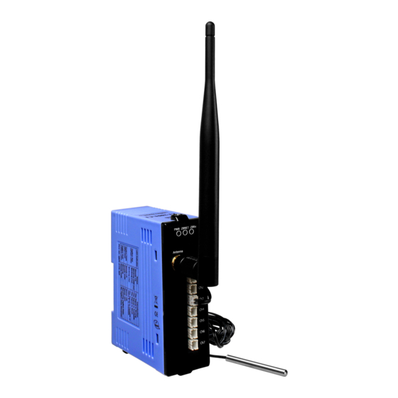
1.2 Introduction to the ZT-2005-C8 The ZT-2005-C8 is an 8 channel thermistor input module, it can monitor the resistance change of thermistor to get temperatue. The ZT-2005-C8 is a wireless ZigBee module, it need to communicate with ZigBee coordinator. The information of ZigBee coordinator can refer ZT-2550 or ZT-2570. -
Page 7: Hardware Information
Power consumption 1 W (Max.) Intra-module Isolated, Field-to-Logic 1000 V Analog Input Input channels Input Type Thermistor Resolution 12 bits ICP DAS, ZT-2005-C8 User Manual, Version v1.0.1 Page 7 Copyright © 2014 by ICP DAS Co., Ltd. All Rights Reserved. - Page 8 R25=10K(Ω)±1% Resistance R25/85=3435(K)±1% B Constant Dissipation Factor ≧3(mW/℃) ≦ 15 (sec) Thermal Time Constant Measuring Temperature Range -40 ~ 105℃ ICP DAS, ZT-2005-C8 User Manual, Version v1.0.1 Page 8 Copyright © 2014 by ICP DAS Co., Ltd. All Rights Reserved.
-
Page 9: Pin Assignments
2.2 Pin assignments ZT-2005-C8 ICP DAS, ZT-2005-C8 User Manual, Version v1.0.1 Page 9 Copyright © 2014 by ICP DAS Co., Ltd. All Rights Reserved. -
Page 10: Setting Up The Zt-2005-C8
User Program Protocol ZT-2005-C8 ZT-2550 ZT-2570 DCON DCON Transparent Transparent Transparent Transparent Modbus RTU Modbus RTU Modbus Gateway Modbus Gateway ICP DAS, ZT-2005-C8 User Manual, Version v1.0.1 Page 10 Copyright © 2014 by ICP DAS Co., Ltd. All Rights Reserved. -
Page 11: Introduction To The Rotary And Dip Switches
3.2 Introduction to the Rotary and DIP Switches The configuration of the ZT-2005-C8 can be adjusted using a combination of the external rotary switch and the DIP switches. The ZT-2005-C8 device should only be rebooted once the configuration is complete. - Page 12 Engineering units Data Format 2’s complement hexadecimal Default, about 11±1 dBm ZigBee RF Power Maximal, about 19 dBm Reserved ----- ----- ICP DAS, ZT-2005-C8 User Manual, Version v1.0.1 Page 12 Copyright © 2014 by ICP DAS Co., Ltd. All Rights Reserved.
-
Page 13: Starting The Zt-2005-C8
The module will automatically start to function on the ZigBee network using the default protocol. ※ Documents: http://ftp.icpdas.com.tw/pub/cd/usbcd/napdos/zigbee/zt_series/document/zt-255x/ http://ftp.icpdas.com.tw/pub/cd/usbcd/napdos/zigbee/zt_series/document/zt-257x/ ※ Configuration Utility (Used to configure ZigBee Coordinator): http://ftp.icpdas.com.tw/pub/cd/usbcd/napdos/zigbee/zt_series/utility/ ICP DAS, ZT-2005-C8 User Manual, Version v1.0.1 Page 13 Copyright © 2014 by ICP DAS Co., Ltd. All Rights Reserved. -
Page 14: Examples
ZigBee RF Channel=0x0E RF Channel 0x02 0x00 Data Format 2’s complement hexadecimal ZigBee Default, about 11±1 dBm RF Power Reserved ----- ----- ICP DAS, ZT-2005-C8 User Manual, Version v1.0.1 Page 14 Copyright © 2014 by ICP DAS Co., Ltd. All Rights Reserved. -
Page 15: Communications Testing
2. Click the “Search” button to start searching for ZT-2005-C8 modules connected to the same ZigBee network. 3. If any ZT-2005-C8 modules are found, they will be displayed in the device list window. Double-click the list of the module name to start the platform to operate the I/O channels. -
Page 16: Format, Type And Calibration
8,o,1 Data Format Setting (FF) Description Reserved Checksum setting 0:Disabled 1:Enabled Data format 00:Engineering unit 01:Reserved 10:2’s complement hexadecimal ICP DAS, ZT-2005-C8 User Manual, Version v1.0.1 Page 16 Copyright © 2014 by ICP DAS Co., Ltd. All Rights Reserved. -
Page 17: Type Code And Data Format Table
7. Repeat steps 2 to 6 three times. Calibration resistor: Zero Calibration Resistor Span Calibration Resistor 150k Ohns 1K Ohms ICP DAS, ZT-2005-C8 User Manual, Version v1.0.1 Page 17 Copyright © 2014 by ICP DAS Co., Ltd. All Rights Reserved. -
Page 18: The Dcon/Modbus Rtu Command Sets
ZT-2005-C8 module can be operated using either the DCON or the Modbus RTU protocol, which can be selected by adjusting the position of DIP Switch 2 to OFF (DCON) or ON (Modbus RTU) and then rebooting the ZT-2005-C8 to use the new protocol. 5.2 The DCON Protocol Command Set The ZT-2005-C8 are controlled via wireless broadcast commands, so each device must have a unique address (or Node ID) that is saved in the EEPROM of the device. -
Page 19: Checksum
Checksum = “AA” DCON Response with Checksum = “!01200600AA(CR)” ※Note: The Checksum is the sum value expressed in capital letters. ICP DAS, ZT-2005-C8 User Manual, Version v1.0.1 Page 19 Copyright © 2014 by ICP DAS Co., Ltd. All Rights Reserved. -
Page 20: Overview Of The Dcon Command Set
Read RF Encryption Setting 5.2.21 Sets the temperature offset of a @AAA2CiToo channel 5.2.22 Reads the temperature offset of @AAA3Ci a channel ICP DAS, ZT-2005-C8 User Manual, Version v1.0.1 Page 20 Copyright © 2014 by ICP DAS Co., Ltd. All Rights Reserved. -
Page 21: Aannttccff
Setting the address 27 to 01, enable checksum and use 2’s Complement Hexadecimal. ※Effect after reboot, and Related Commands: $AA2 ICP DAS, ZT-2005-C8 User Manual, Version v1.0.1 Page 21 Copyright © 2014 by ICP DAS Co., Ltd. All Rights Reserved. - Page 22 Reads the Analog Input channels of module 27, and returns a response indicating that the command was successful, but that the data is over/under range. ※Related Commands: %AANNTTCCFF、$AA2 ICP DAS, ZT-2005-C8 User Manual, Version v1.0.1 Page 22 Copyright © 2014 by ICP DAS Co., Ltd. All Rights Reserved.
-
Page 23: Aan
Read data from Analog Input channel 9 of module 27, but Analog Input channel 8 does not exist. ※Related Commands: %AANNTTCCFF、$AA2 ICP DAS, ZT-2005-C8 User Manual, Version v1.0.1 Page 23 Copyright © 2014 by ICP DAS Co., Ltd. All Rights Reserved. -
Page 24: Aa0Ci
Performs zero calibraction of channel 2 in address 28, and returns a response indicating that the command was not successful. Because the module don’t perform “Enabled/Disabled calibraction” command. ※Related Commands: $AA1Ci、~AAEV ICP DAS, ZT-2005-C8 User Manual, Version v1.0.1 Page 24 Copyright © 2014 by ICP DAS Co., Ltd. All Rights Reserved. -
Page 25: Aa1Ci
Performs span calibraction of channel 2 in address 28, and returns a response indicating that the command was not successful. Because the module don’t perform “Enabled/Disabled calibraction” command. ※Related Commands: $AA0Ci、~AAEV ICP DAS, ZT-2005-C8 User Manual, Version v1.0.1 Page 25 Copyright © 2014 by ICP DAS Co., Ltd. All Rights Reserved. -
Page 26: Aa0
Performs span calibraction of all channels in address 28, and returns a response indicating that the command was not successful. Because the module don’t perform “Enabled/Disabled calibraction” command. ※Related Commands: $AA1、~AAEV ICP DAS, ZT-2005-C8 User Manual, Version v1.0.1 Page 26 Copyright © 2014 by ICP DAS Co., Ltd. All Rights Reserved. -
Page 27: Aa1
Performs zero calibraction of all channels in address 28, and returns a response indicating that the command was not successful. Because the module don’t perform “Enabled/Disabled calibraction” command. ※Related Commands: $AA0、~AAEV ICP DAS, ZT-2005-C8 User Manual, Version v1.0.1 Page 27 Copyright © 2014 by ICP DAS Co., Ltd. All Rights Reserved. -
Page 28: Aa2
Reading the configuration of module address 28, and returns a response indicating that the command was successful. The configuration is enabled checksum and use 2’s Complement Hexadecimal. ※Related Commands: %AANNTTCCFF ICP DAS, ZT-2005-C8 User Manual, Version v1.0.1 Page 28 Copyright © 2014 by ICP DAS Co., Ltd. All Rights Reserved. -
Page 29: Aa5Vv
Setting module address 27 to enable channel 2, 5, 6 and 8 / disabled channel 1, 3, 4 and 7, and returns a response indicating that the command was successful. ※Related Commands: $AA6 ICP DAS, ZT-2005-C8 User Manual, Version v1.0.1 Page 29 Copyright © 2014 by ICP DAS Co., Ltd. All Rights Reserved. -
Page 30: Aa6
Reading module address 27 to enable channel 2, 5, 6 and 8 / disabled channel 1, 3, 4 and 7, and returns a response indicating that the command was successful. ※Related Commands: $AA5VV ICP DAS, ZT-2005-C8 User Manual, Version v1.0.1 Page 30 Copyright © 2014 by ICP DAS Co., Ltd. All Rights Reserved. -
Page 31: Aaf
Reads the firmware version of module 27 and returns a response indicating that the command was successful, and showing that the firmware is version 01.00. ICP DAS, ZT-2005-C8 User Manual, Version v1.0.1 Page 31 Copyright © 2014 by ICP DAS Co., Ltd. All Rights Reserved. -
Page 32: Aam
Response !1BZT-2005-C8 Reads the name of module 27 and returns a response indicating that the command was successful, and that the name of the module is “ZT-2005-C8”. ICP DAS, ZT-2005-C8 User Manual, Version v1.0.1 Page 32 Copyright © 2014 by ICP DAS Co., Ltd. All Rights Reserved. -
Page 33: Aap
00 meaning that it supports the DCON, Modbus RTU protocols, and the protocol that will be used at the next power on reset is DCON. ICP DAS, ZT-2005-C8 User Manual, Version v1.0.1 Page 33 Copyright © 2014 by ICP DAS Co., Ltd. All Rights Reserved. -
Page 34: Aas1
Sends a command to reload the factory default calibration parameters for module 27 and returns a response indicating that the command was successful. ICP DAS, ZT-2005-C8 User Manual, Version v1.0.1 Page 34 Copyright © 2014 by ICP DAS Co., Ltd. All Rights Reserved. -
Page 35: Aad
. Examples Command ~1BD Response !1B0 Reads the temperature scale of module 27 and returns Celsius. ※Related Commands:~AADT ICP DAS, ZT-2005-C8 User Manual, Version v1.0.1 Page 35 Copyright © 2014 by ICP DAS Co., Ltd. All Rights Reserved. -
Page 36: Aadt
Examples Command ~1BDF Response Sets the temperature scale of module 27 to Fahrenheit, and returns a valid response. ※Related Commands:~AAD ICP DAS, ZT-2005-C8 User Manual, Version v1.0.1 Page 36 Copyright © 2014 by ICP DAS Co., Ltd. All Rights Reserved. -
Page 37: Aaev
Examples Command ~1BE1 Response Enabled calibration of module address 27, and returns a valid response. ※Related Commands:$AA0、$AA1、$AA0Ci、$AA1Ci ICP DAS, ZT-2005-C8 User Manual, Version v1.0.1 Page 37 Copyright © 2014 by ICP DAS Co., Ltd. All Rights Reserved. -
Page 38: Aare
Read the RF encryption status of module address 27, and returns avalid response that module supports encryption function and alredy be enabled. ※ZT-2005-C8 will follow the wireless data format of ZT-2550 or ZT-2570, and enable or disable encryption AES 128 encryption automatically, so users don’t need to set again. -
Page 39: Aaa2Citoo
Response Sets the offset value -1.6℃ of channel 5 in module address 27, and returns a valid response. ※Related Commands:@AAA3Ci ICP DAS, ZT-2005-C8 User Manual, Version v1.0.1 Page 39 Copyright © 2014 by ICP DAS Co., Ltd. All Rights Reserved. -
Page 40: Aaa3Ci
!1BFC Reads the offset value -0.4℃ of channel 5 from module address 27, and returns a valid response. ※Related Commands:@AAA2CiToo ICP DAS, ZT-2005-C8 User Manual, Version v1.0.1 Page 40 Copyright © 2014 by ICP DAS Co., Ltd. All Rights Reserved. -
Page 41: Modbus Rtu Protocol
The Modbus protocol was originally developed for Modicon controllers by Modicon Inc. Detailed information related to the Modbus RTU protocol can be found at http://www.modbus.org for more valuable information. The Modbus RTU functions of ZT-2005-C8 module are supported as bellow. Field Field... -
Page 42: Modbus Address Mapping
Module address (Address/Node ID), valid range:1~247 30486 40486 Baud rate. Always set to 0x0A (115200,8,n,1) 30490 40490 Enables or disables each Analog Input channel ICP DAS, ZT-2005-C8 User Manual, Version v1.0.1 Page 42 Copyright © 2014 by ICP DAS Co., Ltd. All Rights Reserved. -
Page 43: Function 01(0X01)-Read Coils
Reads the temperature scale of module address 26, and response 0: Celsius(℃). Response 1A 01 01 01 [96 AC] Reads the temperature scale of module address 26, and response 1: Fahrenheit(℉). ICP DAS, ZT-2005-C8 User Manual, Version v1.0.1 Page 43 Copyright © 2014 by ICP DAS Co., Ltd. All Rights Reserved. -
Page 44: Function 02(0X02)-Read Discrete Inputs
Reads the temperature scale of module address 26, and response 0: Celsius(℃). Response 1A 02 01 01 [66 AC] Reads the temperature scale of module address 26, and response 1: Fahrenheit(℉). ICP DAS, ZT-2005-C8 User Manual, Version v1.0.1 Page 44 Copyright © 2014 by ICP DAS Co., Ltd. All Rights Reserved. -
Page 45: Function 03(0X03)-Read Multiple Registers
Reads temperature value of channel1 to 5 from module address 26, and reponse channel 1, 3, 5 are under range, channel 2, 4 are 23.4℃ and 23.7℃. ICP DAS, ZT-2005-C8 User Manual, Version v1.0.1 Page 45 Copyright © 2014 by ICP DAS Co., Ltd. All Rights Reserved. -
Page 46: Function 04(0X04)-Read Multiple Input Registers
Reads temperature value of channel1 to 5 from module address 26, and reponse channel 1, 3, 5 are under range, channel 2, 4 are 23.4℃ and 23.7℃. ICP DAS, ZT-2005-C8 User Manual, Version v1.0.1 Page 46 Copyright © 2014 by ICP DAS Co., Ltd. All Rights Reserved. -
Page 47: Fuction 05(0X05)-Write Single Coil
1A 05 01 0A FF 00 [AE 2F] Response 1A 05 01 01 [D7 6D] Writes the temperature scale 1 Fahrenheit(℉) to module address 26. ICP DAS, ZT-2005-C8 User Manual, Version v1.0.1 Page 47 Copyright © 2014 by ICP DAS Co., Ltd. All Rights Reserved. -
Page 48: Function 06(0X06)-Write Single Register
1A 06 01 27 FF 80 [7B 86] Writes the temperature offset -12.8℃ of channel 7 to module address 26. ICP DAS, ZT-2005-C8 User Manual, Version v1.0.1 Page 48 Copyright © 2014 by ICP DAS Co., Ltd. All Rights Reserved. -
Page 49: Function 15(0X0F)-Write Multiple Coils
1A 0F 01 0A 00 01 01 01[36 38] Response 1A 0F 01 0A 00 01 [B6 1E] Writes the temperature scale 1 Fahrenheit(℉) to module address 26. ICP DAS, ZT-2005-C8 User Manual, Version v1.0.1 Page 49 Copyright © 2014 by ICP DAS Co., Ltd. All Rights Reserved. -
Page 50: Function 16(0X10)-Write Multiple Registers
1A 10 01 27 00 01 [B3 D5] Writes the temperature offset -12.8℃ of channel 7 to module address 26. ICP DAS, ZT-2005-C8 User Manual, Version v1.0.1 Page 50 Copyright © 2014 by ICP DAS Co., Ltd. All Rights Reserved. -
Page 51: Function 70(0X46)-Read/Write Module Setting
Description Value Module address 1~247 Function Code 0xC6 Exception Code Refrt to section 5.3 03~04 Checksum (CRC16) Two bytes checksum ICP DAS, ZT-2005-C8 User Manual, Version v1.0.1 Page 51 Copyright © 2014 by ICP DAS Co., Ltd. All Rights Reserved. -
Page 52: Sub-Function 00(0X00)-Read Module Name
1A 46 00 [62 67] Response 1A 46 00 54 20 05 C8 [BD 5B] Reads the module name is ZT-2005-C8 from module address 26. ICP DAS, ZT-2005-C8 User Manual, Version v1.0.1 Page 52 Copyright © 2014 by ICP DAS Co., Ltd. All Rights Reserved. -
Page 53: Sub-Function 04(0X04)-Write Module Address
1A 46 04 00 00 00 00 [5F A7] Sets the new module address 03 to module address 26, and return setting OK. ICP DAS, ZT-2005-C8 User Manual, Version v1.0.1 Page 53 Copyright © 2014 by ICP DAS Co., Ltd. All Rights Reserved. -
Page 54: Sub-Function 05(0X05)-Read The Communication Setting
1A 46 05 00 0A 00 00 00 01 00 00 [55 A7] Reads the mode from the flash ROM of module address 26 is Modbus RTU. ICP DAS, ZT-2005-C8 User Manual, Version v1.0.1 Page 54 Copyright © 2014 by ICP DAS Co., Ltd. All Rights Reserved. -
Page 55: Sub-Function 32(0X20)-Read Module Firmware Version
1A 46 20 [63 BF] Response 1A 46 20 01 00 00 [D1 EE] Reads the firmware version 1.0 from module address 26. ICP DAS, ZT-2005-C8 User Manual, Version v1.0.1 Page 55 Copyright © 2014 by ICP DAS Co., Ltd. All Rights Reserved. -
Page 56: Sub-Function 37(0X25)-Read The Enabled/Disable Status Of Channels
Reads the enable/disable status of channels from module address 26, and reponse channel 0, 2, 4, 6 are disable, channel 1, 3, 5, 7 are enable. ICP DAS, ZT-2005-C8 User Manual, Version v1.0.1 Page 56 Copyright © 2014 by ICP DAS Co., Ltd. All Rights Reserved. -
Page 57: Sub-Function 38(0X26)-Write The Enabled/Disable Status Of Channels
Sets the enable/disable status of channels from module address 26, and reponse channel 0, 2, 4, 6 are disable, channel 1, 3, 5, 7 are enable. ICP DAS, ZT-2005-C8 User Manual, Version v1.0.1 Page 57 Copyright © 2014 by ICP DAS Co., Ltd. All Rights Reserved. -
Page 58: Troubleshooting
Troubleshooting (1) Technical Support If you have any difficulties using your ZT-2005-C8 device, please send a description of the problem to service@icpdas.com Include the following items in your email: A description or diagram of the current DIP switch positions. -
Page 59: Appendix
7.2 The Extension to the Software Address There are only 31 adjustable addresses available to the DIP and rotary switches for the ZT-2005-C8 module. If there are any requirments for more range of addresses, there is a software configuration feature for the Address parameter. - Page 60 Finally, we only turn the Address of DIP and rotary switches to address 0 and reboot module, the software address will be enabled. The default software address is 0x01. ICP DAS, ZT-2005-C8 User Manual, Version v1.0.1 Page 60 Copyright © 2014 by ICP DAS Co., Ltd. All Rights Reserved.
Need help?
Do you have a question about the ZT-2005-C8 and is the answer not in the manual?
Questions and answers