
Related Manuals for ICP DAS USA WF-2572


Summary of Contents for ICP DAS USA WF-2572
- Page 1 WF-2572 Ethernet to Wi-Fi Bridge User Manual v1.00 www.icpdas.com WF-2572, Ethernet to Wi-Fi Bridge (V1.00, 2018/09/30) 1...
- Page 2 The names used for identification only may be registered trademarks of their respective companies. Technical Support _______________________________________________ If you have any problems, feel free to contact us via e-mail at service@icpdas.com Document Revision Version Date Note 1.00 2018/09/30 Release version WF-2572, Ethernet to Wi-Fi Bridge (V1.00, 2018/09/30) 2...
-
Page 3: Table Of Contents
....................18 NFRASTRUCTURE ETTING ESCRIPTION Test Architecture ..........................18 4.4.1 Setting step ............................19 4.4.2 Query device MAC by using WF-2572 utility ................... 20 4.4.3 ............................ 22 -AP M IMIT Test Architecture ..........................22 4.5.1 Setting step ............................22 4.5.2... -
Page 4: Introduction
Wi-Fi to wire internet without complex settings. The WF-2572 also supports dual bands (2.4/5 GHz). The 2.4 GHz is more crowded than 5 GHz. Therefore, the devices on 2.4 GHz suffer much more interference than the ones on 5 GHz. The WF-2572 has less interference on 5 GHz. -
Page 5: Feature
No driver installation required Built-in Watchdog Extended operating temperature range (-25°C ~ +75°C) Utility Configuration by USB interface Support setting of Wi-Fi Infrastructure and Limit-AP mode Figure 1-2. WF-2572 Utility WF-2572, Ethernet to Wi-Fi Bridge (V1.00, 2018/09/30) 5... -
Page 6: Hardware
1 .6 W Power Consumption Mechanism Casing Plastic Installation DIN-Rail Dimensions 33mm x 95mm x 120mm (W x L x H) Environment -25℃ ~ +75℃ Operation Temp. -30℃ ~ +80°C Storage Temp. Humidity 10~90% WF-2572, Ethernet to Wi-Fi Bridge (V1.00, 2018/09/30) 6... -
Page 7: Wf-2572 Appearance
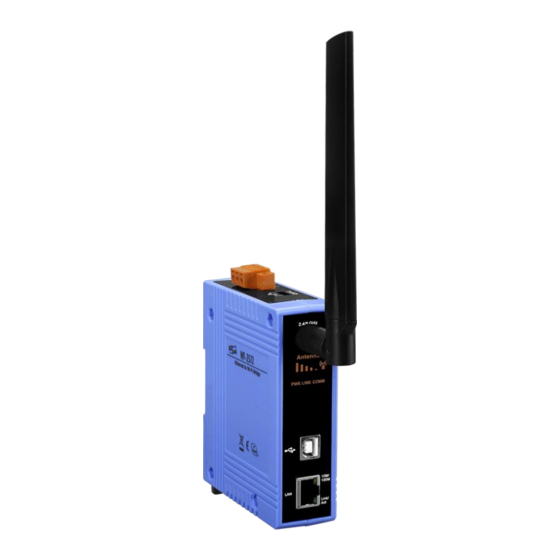
WF-2572 Appearance 2.2.1 Front Panel The WF-2572 front panel contains the antenna, USB connector, Ethernet connector and LEDs. RP SMA Connector Signal Strength LED Indicator System Status LED Indicator USB/Ethernet Connector Figure 2-1. Front Panel of the WF-2572 WF-2572, Ethernet to Wi-Fi Bridge (V1.00, 2018/09/30) 7... -
Page 8: Top Panel
2.2.2 Top Panel The WF-2572 top panel contains the power connector and operating mode selector switch. FW mode: Firmware update mode OP mode: Firmware operation mode 11 Power Connector Operating mode selector switch Figure 2-2. Top Panel of WF-2572 Table 2-1. -
Page 9: Led Indicator
Signal strength: High Signal strength: Medium Signal strength Signal strength: Low Unconnected Always ON Power Good Power (PWR) Power failure Blink/Always ON Unconnected Connection Status(LINK) Connected Data transmission Blink Communication(COMM) Bus Idle WF-2572, Ethernet to Wi-Fi Bridge (V1.00, 2018/09/30) 9... -
Page 10: Power Wire Connection
The WF-2572 supplies a jumper for users to active the watchdog timer or not. Inside the WF-2572 users can use the JP1 to activate the WDT built in the module, as the Figure 2-6. Note that the default setting is active. - Page 11 WF-2572 via USB interface and it will become a “USB Mass Storage Device” and shows a folder automatically. Figure 2-5. FW update position of Dip-Switch Figure 2-6. USB Mass Storage Device Users just need to execute “Firmware_Update_Tool.exe” and follow the below steps to complete the firmware updating process.
-
Page 12: Firmware Operation Mode
As shown in Figure 2-8, Users need to set the dip-switch to the “OP” position and reset the power, which the WF-2572 can run in the operation mode. In this mode, user can use the WF- 2572 with a computer or other devices that have Ethernet interface for wireless connection. - Page 13 Top View Bottom View Figure 2-10. Top / Bottom side dimension of the WF-2572 WF-2572, Ethernet to Wi-Fi Bridge (V1.00, 2018/09/30) 13...
-
Page 14: Software
3. Software This chapter explains how to use the WF-2572 Utility to carry on the WF-2572 wireless communication configuration. 3.1 Wireless Configuration Tool – WF-2572 Utility WF-2572 utility is a Microsoft Windows application that compatibles with Microsoft Windows XP, 7 and 10. -
Page 15: Wi-Fi Parameter
1. It can set the AP’s SSID when the mode is “Limit-AP”. SSID 2. The SSID mean that the Wi-Fi AP which WF-2572 would like to connect when the mode is “Infrastructure”. * Connected devices must be with the same SSID Operation Band The operation band of WF-2572. -
Page 16: Ip Setting
Ethernet interface. The WF-2572 will convert the Ethernet to Wi-Fi interface. The WF-2572 will connect to the Wi-Fi AP at the infrastructure mode. The Wi-Fi AP can be WF-2572, Ethernet to Wi-Fi Bridge (V1.00, 2018/09/30) 16... -
Page 17: System Architecture Of Limit-Ap Mode
The system architecture of infrastructure mode shows in Figure 4-2. The WF-2572 has only one LAN port. But it can use the Ethernet switch to extend LAN port. The WF-2572 can connect by other Wi-Fi stations in the “Limit-AP” mode. The Wi-Fi can be WF-2572 or other Wi-Fi devices. -
Page 18: Hardware Installation
4.4 Infrastructure Setting Description 4.4.1 Test Architecture The test architecture shows in Figure 4-4. The WF-2572 connects to the PC by Ethernet interface. The Wi-Fi AP connects to other PC by Ethernet interface. The WF-2572 set to “Infrastructure” mode that it connects to the Wi-Fi AP. -
Page 19: Setting Step
4.4.2 Setting step The WF-2572 has three steps. The setting step shows as following: Set WF-2572 to “Infrastructure” mode and Wi-Fi parameter Step1. 1. Change “Mode” to “Infrastructure” 2. Set AP SSID 3. Set authentication of Wi-Fi 4. Set password of Wi-Fi 5. -
Page 20: Query Device Mac By Using Wf-2572 Utility
According to the type of device, it can be divided into different query methods. When the device is computer, it can use the command line windows to query the MAC address. If the device is PLC or other Ethernet devices, it can use the WF-2572 utility to query the MAC address. - Page 21 Step1. Connect the Ethernet cable between computer and PLC It needs to remove the Ethernet cable between device (PLC or other Ethernet devices) and WF-2572. After that, you can connect the Ethernet to the computer. Step2. Execute WF-2572 utility 1. Click the “Get MAC” button after executing the WF-2572 utility.
-
Page 22: Limit-Ap Mode
4.5 Limit-AP Mode 4.5.1 Test Architecture The test architecture has shown in Figure 4-10. Both of WF-2572 connects to the computer by Ethernet. One of the WF-2572 sets to the Limit-AP mode. The other WF-2572 sets to the Infrastructure mode. 2.4/5 GHz... - Page 23 Figure 4-11. Setting Wi-Fi Parameter Step2. The WF-2572’s Infrastructure setting can refer to chapter 4.4. Step3. Setting PC’s IP 1. As shown in Figure 4-12, the PC’s is “192.168.255.10” and “192.168.255.11”. Figure 4-12. Setting PC’s IP Step4. Internet Connection ) + R will show you the “RUN” box where you can type commands 1.
- Page 24 3. As shown in Figure 4-13, the internet access is working fine that it should show a similar reaction as following figures. Figure 4-13. Ping Success Technical Support Please contact us if you have any questions about products. ICP DAS website: http://www.icpdas.com Email: service@icpdas.com WF-2572, Ethernet to Wi-Fi Bridge (V1.00, 2018/09/30) 24...
Need help?
Do you have a question about the WF-2572 and is the answer not in the manual?
Questions and answers