
Summary of Contents for Kauai Labs navX2-MXP
- Page 1 Robotics Navigation Sensor User Guide Kauai Labs Creative Commons - BY — 2020...
-
Page 2: Table Of Contents
Table of Contents Overview navX2-MXP Features Technical Specifications "Behind the Design" Frequently-asked Questions Installation Installation RoboRIO Installation FTC Installation Orientation OmniMount I/O Expansion Alternative Installation Options Creating an Enclosure Software Software RoboRIO Libraries Android Library (FTC) Linux Library Arduino Library... - Page 3 Serial Protocol Register Protocol Open-source Hardware/Software "Classic" navX-MXP Firmware Customization navXUI Customization Technical References...
-
Page 4: Overview Navx2-Mxp
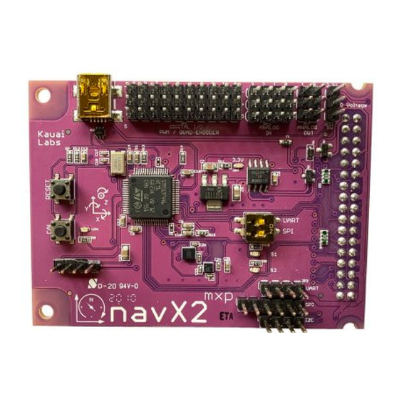
“Generation 2” navX2-MXP is a drop-in replacement for “Classic” navX2-MXP. See the Frequently Asked Questions (FAQ) for more information about navX2-MXP improvements. navX2-MXP is a must-have add on to any RoboRIO-based control system, and includes free software libraries, example code and many more features. -
Page 5: Features
Alternatively, the navX2-MXP enclosure can be purchased online. Firmware updates can be easily downloaded to the navX2-MXP circuit board via the USB port. Technical Specifications The navX2-MXP circuit board and official firmware provide inertial and magnetic measurements, with a... -
Page 6: Behind The Design
Overview Technical Specifications Note that certain performance specifications are only valid after Startup Gyroscope/Accelerometer Calibration period, during which time the navX2-MXP circuit board must be held still. Additional details can be found in the navX2-MXP datasheet. Product Performance Specifications: Electrical Specifications... -
Page 7: Frequently-Asked Questions
Overview "Behind the Design" navX-MXP on Team 624’s 2015 Robot Team 2062’s 2015 Robot navX-MXP on Team 2062’s 2015 Robot About the “Behind the Design” Book “Behind the Design – 30 Profiles of Design, Manufacturing and Control” has six chapters that focus on CAD modeling, traditional machining, CNC mills and lathes, CNC cutting, 3D printing, and sensors/control. - Page 8 Technical Specifications. If I currently use the “Classic” navX-MXP, how easy is it to upgrade to the new navX2-MXP? Simply swap out the existing navX-MXP, replacing it with the new “Generation 2” navX2-MXP. navX2-MXP is identical to navX-MXP from both a hardware and software interface perspective; it’s a...
- Page 9 Overview Frequently-asked Questions Why is a 4000 degree/second gyroscope like that present on navX2-MXP useful on a FRC robot? Simply put, this minimizes yaw errors during high-inertia (e.g., impact) events. Current consumer-class IMUs typically found on FRC robots (e.g., the “classic” navX-MXP) are limited to measuring rotation at 2000 degrees/second.
- Page 10 ~.2 degree per hour when still. For further details, please see the Drift page. Can the navX2-MXP “Displacement” estimates be used for tracking a FRC or FTC robot’s change in position (dead-reckoning) during autonomous? Accelerometer data from the navX-MXP’s onboard MPU-9250 are double-integrated by the navX- MXP firmware to estimate displacement, and are accurate to approximately .1 meter of error...
- Page 11 KauaiLabs actively researches these technology developments – efforts that led to the selection of the ISM330DHCX for navX2-MXP – and projects that MEMS technology that is both (a) low noise (1 micro-g per square root hertz) and (b) available at low cost will likely occur in the next decade, but technology has not advanced to this point yet.
-
Page 12: Installation
National Instruments RoboRIO™. This installation takes about only a minute. To install, simply place the 34-pin “MXP” Connector on the bottom of the navX2-MXP circuit board into the corresponding MXP slot on the top of the RoboRIO, as shown below. - Page 13 Installation RoboRIO Installation...
-
Page 14: Ftc Installation
Securing the navX2-MXP circuit board and RoboRIO to the robot chassis The navX2-MXP circuit board should be mounted such that it is firmly attached to the robot chassis. The quality of this mounting will be directly reflected in the quality of navX2-MXP inertial measurements. - Page 15 Therefore you likely need to re-order the pins on this end of the connector to correctly match the navX2-MXP pinout, by carefully removing and re-inserting the wire leads into the connector.
- Page 16 Expansion Control Hub match the corresponding pins on the navX2-MXP. Physical Installation on the Robot The navX2-MXP circuit board should be mounted such that it is firmly attached to the robot chassis. The quality of this mounting will be directly reflected in the quality of navX2-MXP inertial measurements.
-
Page 17: Orientation
Orientation navX2-MXP measures a total of 9 sensor axes (3 gyroscope axes, 3 accelerometer axes and 3 magnetometer axes) and fuses them into a 3-D coordinate system. In order to effectively use the values reported by navX2-MXP, a few key concepts must be understood in order to correctly install navX2-MXP on a robot. - Page 18 Coordinate Orientation Standard Body Frame Forward always points to the front (head) of the robot Drive World Frame Forward always points to the Field-oriented front (head) of the field Drive navX2-MXP Board Orientation (Board Frame) Aligning Board Frame and Body Frame...
- Page 19 Since Body Frame and Board Frame coordinates should be aligned, and because the Yaw axis must be aligned with gravity, by default you must orient the navX2-MXP with the top of the board facing up, and with the Y axis (on the circuit board) pointing to the front of the robot.
- Page 20 Installation Orientation...
-
Page 21: Omnimount
RoboRIO (the edge on which the USB connectors are mounted) is pointing up with the top side of the RoboRio pointing towards the front of the robot, the navX2-MXP axes will not be oriented identically to the Robot. This configuration is shown in the diagram below:... - Page 22 Transforming navX2-MXP Board Frame to Body Frame with OmniMount The navX2-MXP’s “OmniMount” feature can transform the navX2-MXP X, Y and Z axis sensor data (Board Frame) into Robot Orientation (Body Frame) by detecting which of its three axes is perpendicular to the earth’s surface.
-
Page 23: I/O Expansion
Install the navX2-MXP circuit board onto your robot. ENSURE that one of the navX2-MXP axes (as shown on the navX2-MXP circuit board) is perpendicular to the earth’s surface. This axis will become the yaw (Z) axis. Note that this axis can either be pointing away from the earth’s surface, or towards the earth’s surface. - Page 24 Installation I/O Expansion...
- Page 25 Each of the 10 Digital I/O pins may be configured for use as either DigitalInputs or DigitalOutputs, PWM (Outputs) or Counters (Inputs). Additionally, multiple (either 2 or 3) DigitalInputs may be used to form an QuadratureEncoder input. DigitalInput/DigitalOutput Addressing navX2-MXP Port MXP Pin Number RoboRIO Channel Address DIO0...
- Page 26 NOTE: The MXP connector has 2 Digital I/O pins which are dedicated to the I2C interface. MXP Digital I/O Pin DIO14 is used for I2C SCL and DIO15 is used for I2C SDA. Since the navX2-MXP I2C interface is always active, these pins must not be used for any other purpose.
-
Page 27: Alternative Installation Options
Installation I/O Expansion The navX2-MXP I2C connector can be used to connect the RoboRIO to an external I2C Device. The RoboRIO functions as an I2C Master. The connector provides DC Voltage, Ground, Clock (SCL) and Data (SDA). Note that this I2C connector resides on the same I2C bus which may optionally be used to communicate between the RoboRIO and the navX2-MXP’s onboard processor. - Page 28 If mounting the navX2-MXP circuit board directly into the RoboRIO’s onboard MXP connector is not possible, a “Floppy-disk” extension cable can be used to place the navX2-MXP circuit board up to a few feet away from the RoboRIO. This installation method supports the I/O expansion capabilities, since all MXP connector signals are carried over the extension cable.
-
Page 29: Creating An Enclosure
To use the I2C interface without directly plugging the navX2-MXP circuit board into the RoboRIO MXP connector, first ensure that the navX2-MXP circuit board has power (either via the USB connector, or via the +5VDC pin on the MXP connector). - Page 30 Sketchup 3D Design File for a lid-style enclosure for the navX2-MXP / navX-MXP circuit boards. Note that the design file scale is 1000X actual size, so will need to be scaled down by a factor of 1000 before printing.
- Page 31 The Lid Enclosure can be secured to the RoboRIO by two #4-40 1/2? screws. This will secure not only the Lid, but will also secure the navX2-MXP circuit board. Note that when using the Lid Enclosure, the required screw length is typically longer than the default...
-
Page 32: Software
Please note that this build does not contain any of the navX2-MXP tools, but does contain the RoboRIO and Android libraries. RoboRIO Libraries navX2-MXP libraries for use with the RoboRIO Libraries from WPI are available in each of the languages/development environments commonly used to development FIRST FRC robot applications: Java LabVIEW navX-AE These libraries provide access to a navX2-MXP sensor (as well as the “Classic”... -
Page 33: Android Library (Ftc)
Software RoboRIO Libraries Android Library (FTC) NOTE: The 2019 Version of the navX-sensor Android Library for FTC has currently been tested with the FTC “ftc_app” library for the 2019 season, and has been verified to operate correctly with the REV Expansion and Control Hubs. - Page 34 Software Android Library (FTC) Next, several configuration changes must be made in order that the Android Studio ftc_app-based project can locate the navx_ftc library: Modify any of the op mode example files to change the following line near the top of the file to match the “Device name”...
-
Page 35: Linux Library
'libs','/Users/Robot/navx-mxp/android/libs' Linux Library A library for accessing navX2-MXP and navX2-Micro (as well as the “Classic” navX-MXP and navX-Micro sensors) from Linux is available. This library was developed by Alexander Allen of FRC Team 900 (Zebracorns) and supports the USB interface. -
Page 36: Navxui
Software Arduino Library A library for accessing nav2X-MXP and navX-Micro (as well as “Classic” navX- MXP and navX-Micro sensors) from Arduino is available. This library supports the I2c and SPI interfaces. The navX-sensor Arduino Library is useful for integrating a navX-sensor into Arduino-based project. To use the library, you can checkout the source code with Git. - Page 37 Software navXUI Gyro Calibration in Progress Indicator The Gyro Calibration in Progress Indicator is displayed during initial gyroscope calibration, which occurs immediately after power is applied to the navX-sensor. If the gyroscope calibration does not complete, the navX-sensor yaw accuracy will be adversely impacted. For more information on Gyro Calibration, please see the Gyro/Accelerometer Calibration page.
- Page 38 Calibration is complete, the Yaw Angle text color will change to white. Pitch/Roll Angles The Pitch/Roll Angles are always displayed in white text, since Accelerometer calibration occurs at the Kauai Labs factory. Compass Angle The Compass Angle displays the tilt-compensated compass heading calculated from the navX-sensor’s Magnetometer combined with the tip/tilt measure from the Accelerometers.
-
Page 39: Tools
USB with the navX-sensor, as well as some additional tools. Start the navXUI: From your Start Menu, select “Kauai Labs” and then the type of navX-Sensor you are using, and click on the “navXUI” icon to start the navXUI. -
Page 40: Examples
Examples Examples Examples Examples Example source code for various navX-sensor capabilities are available for both for FRC and FTC Robotics Control Systems. FRC Examples This section provides example code for several common navX-sensor applications used by FIRST FRC teams on their robots to add sophisticated navigation capabilities. These examples are in Java, C++ and LabVIEW. - Page 41 Examples Field-Oriented Drive (FRC) An easy-to-use, highly-maneuverable drive system is at the heart of a successful FIRST Robotics Challenge (FRC) robot. Omnidirectional drive systems provide motion in the Y axis (forward-backward), X-axis (strafe), and Z axis (rotating about it’s center axis). Each “degree of freedom”...
- Page 42 Examples Field-Oriented Drive (FRC) fwd = temp; /* At this point, Joystick X/Y (strafe/forwrd) vectors have been /* rotated by the gyro angle, and can be sent to drive system */ The WPI Library “MecanumDrive_Cartesian()” function and the LabView “Holonomic Drive” VI, which are used in the examples below, implement the field-centric drive algorithm.
- Page 43 Examples Field-Oriented Drive (FRC) Teleop.vi The Teleop.vi is modified to feed the current navX-sensor “Yaw” angle reading to the Holonomic Drive VI, which rotates the joystick X/Y coordinates by the gyro angle (and thus implements FieldCentric drive control). Additionally, if a driver joystick button is pressed, the navX-sensor “Yaw” angle is reset to zero. The navX Device TypeDef is passed to the Teleop.vi via a VI input terminal.
-
Page 44: Rotate To Angle (Frc)
Examples Field-Oriented Drive (FRC) Full LabVIEW Source code on Github Rotate to Angle (FRC) Automatically rotating a robot to an angle using a navX-sensor can be used to rotate a robot quickly and accurately to a known angle, as long as the robot drive system provides independent Z-axis rotation (the capability to “spin on a dime”). - Page 45 Examples Rotate to Angle (FRC) system, this Java example is available. For more details on this approach, please visit Chief Delphi, including this helpful post. FRC C++ Example Full C++ source code on GitHub FRC Java Example Full Java Source code on GitHub FRC LabView Example The navX-sensor Rotate to Angle LabView example shows how to make small modifications to the LabView “FRC RoboRIO Robot Project”...
- Page 46 Examples Rotate to Angle (FRC) Teleop.vi The Teleop.vi is modified to feed the current navX-sensor “Yaw” angle reading to the Holonomic Drive VI, which rotates the joystick X/Y coordinates by the gyro angle (and thus implements FieldCentric drive control). Additionally, if a driver joystick button is pressed, the navX-sensor “Yaw” angle is reset to zero. This example also includes a “Rotate to angle”...
-
Page 47: Automatic Balancing (Frc)
Examples Rotate to Angle (FRC) Full LabVIEW Source code on Github Automatic Balancing (FRC) The Automatic Balancing example demonstrates how to implement a self-balancing robot, which can be useful to help avoid a robot tipping over when driving. As an example, FRC team 263 demonstrated the auto-balance feature effectively during the 2018 FRC Championships. - Page 48 Examples Automatic Balancing (FRC) FRC C++ Example Full C++ source code on GitHub FRC Java Example Full Java Source code on GitHub FRC LabView Example The navX-sensor AutoBalance LabView example shows how to make small modifications to the LabView “FRC RoboRIO Robot Project” using the “Mecanum Robot” configuration to implement high- accuracy Automatic Balancing.
- Page 49 Examples Automatic Balancing (FRC) Teleop.vi The Teleop.vi is modified to feed the current navX-sensor “Yaw” angle reading to the Holonomic Drive VI, which rotates the joystick X/Y coordinates by the gyro angle (and thus implements FieldCentric drive control). Additionally, if a driver joystick button is pressed, the navX-sensor “Yaw” angle is reset to zero. Finally, the navX-sensor “Pitch”...
-
Page 50: Collision Detection (Frc)
Examples Automatic Balancing (FRC) Full LabVIEW Source code on Github Collision Detection (FRC) Collision Detection is commonly used in automobiles to trigger airbag deployment, which can reduce the force of an impact and save lives during an accident. A similar technique can be used on a robot to detect when it has collided with another object. - Page 51 Examples Collision Detection (FRC) In the sample code shown below, both the X axis and the Y axis jerk are calculated, and if either exceeds a threshold, then a collision has occurred. The “collision threshold” used in these samples will likely need to be tuned for your robot, since the amount of jerk which constitutes a collision will be dependent upon the robot mass and expected maximum velocity of either the robot, or any object which may strike the robot.
- Page 52 Examples Collision Detection (FRC) 50Hz. You may need to process faster for your situation. For the SPI, I2C and USB connections the max sample rate is 200Hz. Teleop.vi The Teleop.vi is modified to feed the Linear Acceleration to a threshold detector to determine if a collision has occurred.
-
Page 53: Motion Detection (Frc)
Examples Collision Detection (FRC) Full LabVIEW Source code on Github Motion Detection (FRC) Detecting motion/no-motion can be simply detected by determining if a body’s linear acceleration exceeds a small threshold. Using the data directly from accelerometers, this is not as easy as it seems, since raw accelerometer readings contain both acceleration due to gravity as well as acceleration due to a body’s motion. - Page 54 Examples Motion Detection (FRC) Full C++ Source Code FRC Java Example Full Java Source Code FRC LabView Example The navX-sensor AutoBalance LabView example shows how to make small modifications to the LabView “FRC RoboRIO Robot Project” using the “Mecanum Robot” configuration to detect when your robot is moving.
-
Page 55: Data Monitor (Frc)
Examples Motion Detection (FRC) Teleop.vi The Teleop.vi is modified to detect when the robot has motion. Full LabVIEW Source code on Github Data Monitor (FRC) The Data Monitor example code demonstrates how to perform navX-MXP initialization and display all sensor values on a FIRST FRC robotics dashboard. The output data values include: Yaw, Pitch and Roll angles Compass Heading and 9-Axis Fused Heading (requires Magnetometer calibration) Linear Acceleration Data... - Page 56 Examples Data Monitor (FRC) Quaternion Data Raw Gyro, Accelerometer and Magnetometer Data As well, Board Information is also retrieved; this can be useful for debugging connectivity issues after initial installation of the navX-sensor. FRC C++ Example Full C++ source code on GitHub FRC Java Example Full Java Source code on GitHub FRC LabVIEW Example...
- Page 57 Examples Data Monitor (FRC) Test Window.vi Place the Test Window.vi inside of a loop in any VI (for instance in your Teleop.vi loop) and the values will automatically update. Test Window.vi is in the navX-AE “Get” folder.
-
Page 58: Mxp I/O Expansion (Frc)
MXP I/O Expansion (FRC) The “MXP I/O Expansion” example program demonstrates the use of the MXP I/O Expansion capabilities of the navX2-MXP / navX-MXP, including the following capabilities: DIGITAL I/O Pulse-Width Modulation [PWM] (e.g., Motor Control) Digital Inputs (e.g., Contact Switch closure) Digital Outputs (e.g., Relay control) - Page 59 Examples MXP I/O Expansion (FRC) FRC C++ Example Full C++ source code on GitHub FRC Java Example Full Java Source code on GitHub FRC LabView Example The navX MXP IO LabView example shows how to make small modifications to the LabView “FRC RoboRIO Robot Project”...
- Page 60 The InitExpansionIO.vi instantiates the various objects which map onto the navX-MXP Expansion IO Pins. GetChannelFromNavX-MXPPin.vi The GetChannelFromNavX-MXPPin.vi performs the translation from the navX2-MXP / navX-MXP Digital or Analog Pin number to the corresponding RoboRIO Channel Number, which is provided to the various VIs that open that particular port.
- Page 61 Examples MXP I/O Expansion (FRC) Teleop.vi The Teleop.vi reads the Joystick inputs and programs the output pins accordingly (PWM to motor controllers, Digital Outputs and Analog Outputs). As well, values from the input pins (Digital Inputs, Encoders and Analog Inputs) is retrieved and displayed on the Smart Dashboard. Full LabVIEW Project on GitHub...
-
Page 62: Guidance
Guidance Best Practices Guidance Best Practices This page summarizes the recommended best practices when integrating a navX-sensor with the National Instruments RoboRIO™. Following these best practices will help ensure high reliability and consistent operation. 1) Secure the navX-sensor circuit board to the Robot Chassis Excessive vibration will reduce the quality of navX-sensor measurements. - Page 63 Guidance Best Practices isCalibrating() function) before using navX-sensor data. 4) If using the MXP connector, secure the navX-sensor circuit board to the RoboRio During operation of the robot, certain actions (for instance, driving over a bump at high speed) may cause the navX-sensor circuit board to become dislodged from the MXP connector.
-
Page 64: Terminology
If a short occurs between any of the MXP Expansion I/O pins, the POWER led on the RoboRIO will turn red, and the navX-sensor circuit board will not receive power. To protect against accidental shorts, Kauai Labs recommends a protective enclosure that at least partially encases the MXP I/O pins, such as the “lid”-style enclosure... - Page 65 Guidance Terminology Pitch, Roll and Yaw Pitch, Roll and Yaw are measures of angular rotation about an object’s center of mass, and together provide a measure of “orientation” of that object with respect to an “at rest” position. When units of degrees are used, their range is from -180 to 180 degrees, where 0 degrees represents the “at rest”...
- Page 66 Guidance Terminology Forward/Backward + Forward / – Backward Up/Down + Up / – Down Because the gyroscope and accelerometer axes are aligned, a navX-sensor measures linear acceleration in the same set of 3 axes used to measure Pitch, Roll and Yaw. However unlike Pitch, Roll and Yaw, acceleration measures linear motion rather than rotation, and is measured in units of G, with a range of +/- 2.0.
- Page 67 Guidance Terminology only) calculate altitude above sea-level using a pressure sensor. navX-sensor (Aero Edition only) altitude has a range of 0 to 25,000 meters. Important Note: Altitude is calculated based upon barometric pressure. In order to accurately estimate altitude above the earth, navX-sensor should be configured with the sea-level barometric pressure in the surrounding area.
- Page 68 Guidance Terminology Important Note: Because navX-sensor Gyroscopes, Accelerometers and Magnetometers are all aligned to this 3-D Coordinate System, a navX-sensor’s motion processor can also use Sensor Fusion to provide additional information and processing including Tilt Correction, “Fused Heading”, a Gravity Vector, World Reference Frame-based Linear Acceleration and Quaternions, as discussed in the Motion Processing section below.
- Page 69 Guidance Terminology acceleration. This fact makes using raw accelerometer data difficult. A navX-sensor’s automatic accelerometer calibration determines the component of measured acceleration which corresponds to gravity, and uses this information together with gyroscope readings to calculate a gravity vector, which represents acceleration due to gravity.
-
Page 70: Selecting An Interface
Quaternions internally, and also provide the 4 quaternion values for use by those who might need them. Selecting an Interface The navX2-MXP /navX-MXP sensors provide several methods for communicating with robotics control applications: USB 2.0 Streaming vs. Register-based Communication The navX-MXP interfaces fall into two types: Streaming and Register-based. -
Page 71: Gyro/Accelerometer Calibration
Guidance Selecting an Interface Interface Speed Latency Type Cable distance Max Update Type Rate 2 mbps <1ms Register-based <1 meter 400 kbps ~10ms Register-based 1 meter 12 mbps Streaming 6 meters Recommendations Based upon the above, the following recommendations are provided for selecting the best navX-MXP communications interface: –... - Page 72 Guidance Gyro/Accelerometer Calibration The navX-sensor Calibration Process is comprised of three calibration phases: Factory Calibration Startup Calibration On-the-fly Calibration...
- Page 73 Guidance Gyro/Accelerometer Calibration Factory Calibration Before navX-sensors are shipped, the accelerometers and gyroscopes are initially calibrated at the factory; this calibration data is stored in flash memory and applied automatically to the accelerometer and...
- Page 74 Guidance Gyro/Accelerometer Calibration gyroscope data each time the navX-sensor circuit board is powered on. Note that the onboard gyroscopes are sensitive to temperature changes. Therefore, since the average ambient temperature at the factory (on the island of Kauai in Hawaii) may be different than in your environment, you can optionally choose to re-calibrate the gyroscope by pressing and holding the “CAL”...
-
Page 75: Magnetometer Calibration
Guidance Gyro/Accelerometer Calibration determine the yaw offset value it is currently using. NOTE: If navX-sensor is moving during startup, this Yaw Offset Calibration may take longer than 2 seconds, and may not be calculated at all if the sensor continues moving long enough. Therefore it is important to keep a navX-sensor still until initial calibration and Initial Yaw Offset calibration completes. -
Page 76: Yaw Drift
Guidance Magnetometer Calibration Calibration Process The magnetometer calibration encompasses three areas: (a) hard-iron calibration, (b) soft-iron calibration and (c) magnetic disturbance calibration. Hard and soft-iron calibration allows the following equation to be used, and corrects for hard and soft- iron effects due to nearby ferrous metals and magnetic fields. This calibration is necessary in order to achieve valid compass heading readings: Image not found In addition, using the same calibration data the strength of the Earth’s Magnetic Field is determined. - Page 77 Guidance Yaw Drift With the navX-sensor, Quantization error is minimized due to internal signal conditioning, high- resolution 16-bit Analog-to-Digital Converters (ADC), and extremely fast internal sampling (416Hz). Scale factor error is easily corrected for by factory calibration, which the navX-sensor provides. So these two noise sources are not significant in a navX-sensor.
- Page 78 Guidance Yaw Drift older “Classic” navX-MXP sensors used the Invensense MPU-9250 IC, which internally implemented a proprietary algorithm widely believed to be an EKF (it exhibits similar accuracy to documented EKF implementations on MEMS acceleromter/gyroscope sensors). With this processing, navX-sensors exhibit very low yaw drift as documented in the Technical Specifications.
- Page 79 Guidance Yaw Drift that to be effective this requires the magnetometer to be calibrated. Once calibrated, an initial magnetometer reading undisturbed by magnetic disturbances can be acquired at the beginning of a match, before the motors are energized. If the sensor is placed far enough away from motors, it may be possible to also get an undisturbed magnetometer during a match.
-
Page 80: Support
The navX-sensor Discussion Forum “factory test” procedure which can verify the navX-sensor circuit board is functioning properly Firmware Archive The Firmware Archive includes past navX2-MXP and navX2-MXP firmware releases. Please visit navX- Sensor Support to access the firmware archive. Factory Test Procedure The Factory Test Procedure verifies correct operation of the circuit board and it’s key components. - Page 81 Support Software Archive The cross-platform build is also available for non-Windows platforms. Change Summary C++/Java: Added new Simulation Capabilities (on Windows platforms using the WPI “SimDevice” Capabilities) 3D Models: Added STP and 3DS versions of navX-MXP enclosure and circuit board model C++/Java: Added support for accessing the navX-sensor on VMX-pi platforms C++/Java: AHRS Class modified to inherit from Gyro interface C++/Java: Added Device Usage Reporting...
- Page 82 Support Software Archive Change Summary Firmware: Added support for 200Hz Update Rate C++/Java: Added support for 200Hz Update Rate C++/Java: Several updates to accommodate changes to WPI Library API C++/Java: Fix error recovery issue when communicating from RoboRIO via I2C C++/Java: Added user-enabling/disabling of debug logging LabVIEW: Introduction of new navX-AE LabVIEW Library (authored by Tim Easterling) 2016 FRC Season Release...
-
Page 83: Advanced
Advanced Serial Protocol Advanced Serial Protocol In order to communicate sensor data to a client (e.g., a RoboRio robot controller) the navX-sensor software uses a custom protocol. This protocol defines messages sent between the navX-sensor and the client over a serial interface, and includes an error detection capability to ensure corrupted data is not used by the client. - Page 84 Advanced Serial Protocol )(LowByte,LowNibble) Data Type Encoding (Binary) Binary encoding is used for all Binary message elements. All Binary-formatted data types that are signed are encoded as 2’s complement. All multi-byte data types are in little-endian format. Certain non- standard ‘packed’ data types are used to increase storage efficiency. Data Type Range Byte Count...
- Page 85 Advanced Serial Protocol ‘y’ Yaw/Pitch/Roll/Compass Heading ASCII Update ‘g’ Raw Data Update ASCII ‘p’ AHRS + Position Data Update Binary ‘S’ Stream Configuration Command ASCII ‘s’ Stream Configuration Response ASCII ‘I’ Integration Control Command Binary ‘j’ Integration Control Response Binary Message Body The message body differs depending upon the Message Type;...
- Page 86 Advanced Serial Protocol Raw Data Update Message The Raw Data update message communicates the raw gyro, accelerometer, magnetometer and temperature data. This data bypasses the navX-Sensor Motion Processor, and allows the individual sensors to be used directly without any intervening processing. This can allow the following types of use: Access to instantaneous measures of angular velocity in each of the X, Y and Z axes, provided by the tri-axial gyroscopes.
- Page 87 Advanced Serial Protocol Velocity Y Signed 16:16 Meters/Sec Velocity Z Signed 16:16 Meters/Sec Displacement X Signed 16:16 Meters Displacement Y Signed 16:16 Meters Displacement Z Signed 16:16 Meters Quaternion W Signed Pi Radians Pi Radians Quaternion X Signed Pi Radians Pi Radians Quaternion Y Signed Pi Radians...
- Page 88 Advanced Serial Protocol Flags 16-bit Integer Flag value Desription 0, 1 Startup Gyro Calibration in progress Startup Gyro Calibration complete Integration Control Command The Integration Control Command is sent in order to cause certain values being integrated on the navX- sensor to be reset to 0.
- Page 89 Advanced Register Protocol I2C Overview The navX-sensor responds to 7-bit address 50 (0x32) on the I2C bus. If accessing the navX-sensor via the I2C bus, ensure that no other device at that address is on the same bus. The navX-sensor I2C bus operates at a speed up to 400Khz. When accessing the navX-sensor via the I2C bus, this following pattern is used: –...
- Page 90 Advanced Register Protocol When accessing the navX-sensor via the SPI bus, this following pattern is used: – When the SPI bus master is not communicating with the navX-sensor, the SPI bus master must hold the chip select (CS) line high. –...
- Page 91 Advanced Register Protocol – The SPI bus master lowers the CS line. – The SPI bus master initiates a series of SPI bus transactions, where the number of individual 8-bit transfers is equal to the count previously specified, plus one additional transfer for a CRC value transmitted by the nav-sensor.
- Page 92 The navX-MXP project is completely open source, including schematics, firmware and design files for an enclosure. These sources are available online at the navX-MXP Github Repository. “Generation 2” navX2-MXP Sources for the navX-sensor libraries are available online at the navX-MXP Github Repository. "Classic" navX-MXP Firmware Customization The “Classic”...
- Page 93 Advanced "Classic" navX-MXP Firmware Customization Download URL: https://sourcery.mentor.com/sgpp/lite/arm/portal/subscription?@template=lite After installing, the compiler is installed into folder (32-bit Windows) C:\Program Files\CodeSourcery\Sourcery G++ Lite For 64-bit Windows, it is installed into: C:\Program Files (x86)\CodeSourcery\Sourcery G++ Lite Add the path to the “bin” director underneath the Code Sourcery G++ Lite installation directory, so that the compiler is on the path.
- Page 94 Advanced "Classic" navX-MXP Firmware Customization CDT 8.1.2 (or later) A URL for this software, including the CDT, is at: https://www.eclipse.org/downloads/packages/eclipse-ide-cc-developers/junosr2 Install the Zylin embedded CDT Plugin This is installed from within Eclipse, since it is an Eclipse Plugin. If you are unfamiliar with installingn Eclipse plugins, please visit this URL for more information on the process: https://wiki.eclipse.org/FAQ_How_do_I_install_new_plug-ins%3F Zylin Plugin Update URL:...
- Page 95 Advanced "Classic" navX-MXP Firmware Customization The output of the build will be placed in the stm32/Debug directory. The extension of the file will be .hex (Intel HEX Binary format). You can either download this file via the ST Microelectronics DfuSe utility, or you can download it via the ST-LINK/V2 adapter (see instructions on debugging below).
- Page 96 Advanced "Classic" navX-MXP Firmware Customization https://www.freddiechopin.info/en/articles/34-news/92-openocd-w-wersji-080) OpenOCD includes A gdb server that runs with the ST-LINK/V2. MPORTANT NOTE: THe 0.9.0 release of OpenOCD contains a bugfix; earlier releases of OpenOCD from cannot communicate correctly with the STM32F411 microcontroller used in the navX-MXP.
- Page 97 Advanced "Classic" navX-MXP Firmware Customization Starting a Debug Session 6b) To start a debug session, first create a debug configuration: Select Run->Debug Configurations… Select “Zylin Embedded Debug (Cygwin)” Then, add a new configuration (e.g., (navX-MXP OpenOCD Debug Session”); the new configuration will be a child node of Zylin Embedded Debug (Cygwin) On the Debugger Tab: Set GDB Debugger to arm-none-eabi-gdb...
- Page 98 Advanced navXUI Customization Compile/Run the navXUI by selecting the Sketch->Run menu. If your computer has more than one serial port, you will need to select the appropriate serial port (corresponding to the USB serial port navX-MXP is connected to) from the COM port selection drop- down list in the top-right of the navXUI display.
Need help?
Do you have a question about the navX2-MXP and is the answer not in the manual?
Questions and answers