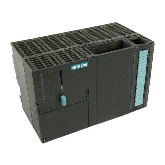
Siemens SIMOTION C 230-2 Operating Instructions Manual
Hide thumbs
Also See for SIMOTION C 230-2:
- Operating instructions manual (196 pages) ,
- Equipment manual (162 pages)
Table of Contents
Advertisement
Quick Links
SIMOTION
SIMOTION C
Operating Instructions
Valid for
SIMOTION C230-2, C240 and C240 PN
11/2022
A5E33441428B
Preface
Fundamental safety
instructions
Description
Operator control (hardware)
Interfaces
Configuring and installing
Connecting
Addressing
Commissioning
Maintenance and servicing
Alarm, error, and system
messages
Technical data
Dimension drawing, spare
parts, and accessories
Standards, Certificates and
Approvals
ESD guidelines
1
2
3
4
5
6
7
8
9
10
11
12
A
B
Advertisement
Table of Contents

Related Manuals for Siemens SIMOTION C 230-2


Summary of Contents for Siemens SIMOTION C 230-2
- Page 1 Preface Fundamental safety instructions Description SIMOTION Operator control (hardware) SIMOTION C Interfaces Configuring and installing Operating Instructions Connecting Addressing Commissioning Maintenance and servicing Alarm, error, and system messages Technical data Dimension drawing, spare parts, and accessories Standards, Certificates and Approvals Valid for SIMOTION C230-2, C240 and C240 PN ESD guidelines...
- Page 2 Note the following: WARNING Siemens products may only be used for the applications described in the catalog and in the relevant technical documentation. If products and components from other manufacturers are used, these must be recommended or approved by Siemens. Proper transport, storage, installation, assembly, commissioning, operation and maintenance are required to ensure that the products operate safely and without any problems.
-
Page 3: Preface
Preface Contents of manual This document is part of the SIMOTION C documentation package. Sections in this manual The following is a list of sections included in this manual along with a description of the information presented in each section. •... - Page 4 European Standards (EN) listed there. You can find detailed information on approvals and standards in the appendix. The current Declaration of Conformity is on the Internet at http://support.automation.siemens.com/WW/view/de/15257461 SIMOTION Documentation An overview of the SIMOTION documentation can be found in the SIMOTION Documentation Overview document.
- Page 5 • Using documentation online (find and search manuals/information) https://support.industry.siemens.com/cs/ww/en/view/109479653 My Documentation Manager Click the following link for information on how to compile documentation individually on the basis of Siemens content and how to adapt it for the purpose of your own machine documentation: https://support.industry.siemens.com/My/ww/en/documentation Training...
- Page 6 (e.g. on mass storage devices, DVD). If this is not possible for technical reasons, Siemens will be happy to send you this OSS source code in exchange for reimbursement of the processing costs. Please contact the address provided at the end of this section.
-
Page 7: Table Of Contents
Table of contents Preface ..............................3 Fundamental safety instructions......................11 General safety instructions....................11 Safety instructions for electromagnetic fields (EMF) ............14 Handling electrostatic sensitive devices (ESD)..............15 Security information ......................15 Note regarding the general data protection regulation............16 Danger to life due to software manipulation when using removable storage media..... - Page 8 Table of contents Configuring and installing ........................79 General requirements ......................79 Configuring an installation using SIMOTION C modules............79 5.2.1 Horizontal and vertical configuration.................. 79 5.2.2 Clearances ........................80 5.2.3 Mounting dimensions of modules ..................81 5.2.4 Layout of modules on a rack....................82 5.2.5 Layout of modules on several racks ..................
- Page 9 Table of contents 8.5.2 Properties of the user memory ..................143 8.5.3 Operations and their effect on the user memory............... 145 Deleting data ........................146 8.6.1 Overview of data deletion ....................146 8.6.2 SIMOTION C memory reset....................147 8.6.3 Deleting user data from Micro Memory Card..............149 8.6.4 Setting SIMOTION C to factory settings................
- Page 10 Table of contents SIMOTION C Operating Instructions, 11/2022, A5E33441428B...
-
Page 11: Fundamental Safety Instructions
Fundamental safety instructions General safety instructions WARNING Electric shock and danger to life due to other energy sources Touching live components can result in death or severe injury. • Only work on electrical devices when you are qualified for this job. •... - Page 12 Fundamental safety instructions 1.1 General safety instructions WARNING Electric shock due to connection to an unsuitable power supply When equipment is connected to an unsuitable power supply, exposed components may carry a hazardous voltage. Contact with hazardous voltage can result in severe injury or death. •...
- Page 13 • If you come closer than around 2 m to such components, switch off any radios or mobile phones. • Use the "SIEMENS Industry Online Support app" only on equipment that has already been switched off. WARNING...
-
Page 14: Safety Instructions For Electromagnetic Fields (Emf)
Fundamental safety instructions 1.2 Safety instructions for electromagnetic fields (EMF) WARNING Unexpected movement of machines caused by inactive safety functions Inactive or non-adapted safety functions can trigger unexpected machine movements that may result in serious injury or death. • Observe the information in the appropriate product documentation before commissioning. •... -
Page 15: Handling Electrostatic Sensitive Devices (Esd)
Siemens' products and solutions undergo continuous development to make them more secure. Siemens strongly recommends that product updates are applied as soon as they are available and that the latest product versions are used. Use of product versions that are no longer supported, and failure to apply the latest updates may increase customers' exposure to cyber threats. -
Page 16: Note Regarding The General Data Protection Regulation
1.6 Danger to life due to software manipulation when using removable storage media Note regarding the general data protection regulation Siemens observes the principles of data protection, in particular the principle of data minimization (privacy by design). For this product this means: The product does not process / store any personal data, only technical functional data (e.g. -
Page 17: Residual Risks Of Power Drive Systems
Fundamental safety instructions 1.7 Residual risks of power drive systems Residual risks of power drive systems When performing the risk assessment for a machine or plant in accordance with the respective local regulations (e.g. EC Machinery Directive), the machine manufacturer or plant constructor must take into account the following residual risks associated with the control and drive components of a drive system: 1. - Page 18 Fundamental safety instructions 1.7 Residual risks of power drive systems SIMOTION C Operating Instructions, 11/2022, A5E33441428B...
-
Page 19: Description
Description System overview C230-2 C240 C240 PN Mode selector Rotary switch Toggle switch Toggle switch Error and status displays Memory module slot for micro memory 32 MB 64 MB 64 MB card I/O interface X1 Drive interface X2 Measuring system interface X3 - X6 Ethernet interface X7 PROFIBUS DP1 interface X8 PROFIBUS DP2/MPI interface X9... - Page 20 Description 2.1 System overview The SIMOTION SCOUT engineering system (ES) is used to configure, parameterize, commission, program perform diagnostics for the SIMOTION C. Where can the SIMOTION C be used? The C230-2, C240 and C240 PN can be used both for positioning and synchronous operation (gearing, camming and path interpolation).
- Page 21 Description 2.1 System overview This approach enables the motion control of axes and machine control within the same system. The same applies to technology functions, such as pressure control of a hydraulic axis. A seamless switch can be made from position-controlled positioning mode to pressure control. Combining the three open-loop control functions of motion control, PLC and technology functions has the following benefits: •...
- Page 22 Description 2.1 System overview Figure 2-3 System overview of C240 PN Components The most important components of a SIMOTION application with SIMOTION C and their functions are listed below. Note The modules and devices approved for the SIMOTION C are listed in the SIMOTION PM 21 Catalog.
- Page 23 Description 2.1 System overview Centralized I/O Table 2-1 SIMOTION C with centralized I/O Component Function SIMOTION C ... is the motion control module. The SIMOTION C supplies the I/O bus with 5 V; communicates over the I/O bus (backplane bus) with the I/O modules.
- Page 24 Description 2.1 System overview Distributed I/O Table 2-2 SIMOTION C with distributed I/O Component Function SIMOTION C ... is the motion control module. • Communicates via two PROFIBUS DP interfaces with: – Programming device (PG/PC) – SIMATIC HMI devices – SIMATIC S7 controllers with PROFIBUS DP interface –...
-
Page 25: I/O Modules Approved For Simotion
A detailed, regularly updated list of the I/O modules approved for use with SIMOTION, as well as notes on their use, can be found on the Internet at: http://support.automation.siemens.com/WW/view/de/11886029 In addition to the I/O modules approved for SIMOTION, all certified standard slaves can, in principle, be connected to SIMOTION if they support the following: •... -
Page 26: The Fundamentals Of Motion Control
Description 2.3 The fundamentals of motion control These modules are integrated via the GSD file from the device manufacturer. Note Please note that in individual cases further boundary conditions must be fulfilled in order to integrate a standard slave into SIMOTION. Some modules need "driver blocks", e.g. in the form of function blocks, which make integration possible or much easier. - Page 27 Description 2.3 The fundamentals of motion control Absolute encoder (SSI, C230-2, C240) Instead of conventional incremental encoders, which supply only a relative dimension for the distance traveled, absolute encoders with a serial interface can be connected. No homing operation need be performed for these encoders as they always supply the absolute position as an actual value.
- Page 28 Description 2.3 The fundamentals of motion control Position-controlled motion control for servo axes (PROFIBUS DP) SIMOTION C enables position-controlled motion control of axes via PROFIBUS DP. Figure 2-6 Servo system with converter, for example SIMODRIVE 611 Universal Stepper motor control (C230-2, C240) In addition to the analog setpoint outputs, the C230-2/C240 has pulse outputs for up to four stepper motor axes.
- Page 29 Description 2.3 The fundamentals of motion control Position-controlled stepper motor control (C230-2, C240) The C230-2, C240 also provide the option of using one encoder input per axis to operate stepper motors in closed-loop position control as a servo axis. Figure 2-8 Position-controlled stepper motor system with control circuit Position-controlled motion control for servo axes (C240 PN, PROFINET IO) The C240 PN enables position-controlled motion control of axes via PROFINET IO.
-
Page 30: Layout Of The Module
Description 2.4 Layout of the module Layout of the module View of the C230-2 The following figure shows the C230-2 module, indicating the interfaces and components on the front panel (fault and status displays). Figure 2-10 Position of the C230-2 interfaces and front panel elements SIMOTION C Operating Instructions, 11/2022, A5E33441428B... - Page 31 Description 2.4 Layout of the module View of the C240 The following figure shows the C240 module, indicating the interfaces and components on the front panel (fault and status displays). Figure 2-11 Position of the C240 interfaces and front panel elements SIMOTION C Operating Instructions, 11/2022, A5E33441428B...
- Page 32 Description 2.4 Layout of the module View of the C240 PN The following figure shows the C240 PN module, indicating the interfaces and components on the front panel (fault and status displays). Figure 2-12 Position of the C240 PN interfaces and front panel elements SIMOTION C Operating Instructions, 11/2022, A5E33441428B...
-
Page 33: Nameplate
Description 2.5 Nameplate Nameplate SIMOTION C type plates The following figures explain the information on the type plate. Note The contents of the individual type plate fields on the current module may differ from those described in this manual (e.g. updated product status, approvals and markings not yet issued, etc.). - Page 34 Description 2.5 Nameplate Figure 2-14 Type plate of the C240 (production version F) Figure 2-15 Additional plate of the C240 (production version F) SIMOTION C Operating Instructions, 11/2022, A5E33441428B...
- Page 35 Description 2.5 Nameplate Figure 2-16 Type plate of the C240 PN (production version D) Figure 2-17 Additional plate of the C240 PN (production version D) SIMOTION C Operating Instructions, 11/2022, A5E33441428B...
- Page 36 Description 2.5 Nameplate Figure 2-18 Type plate of the C240 (production version G) Figure 2-19 Additional plate of the C240 (production version G) SIMOTION C Operating Instructions, 11/2022, A5E33441428B...
-
Page 37: Versions Of Simotion C
Description 2.6 Versions of SIMOTION C Figure 2-20 Type plate of the C240 PN (production version G) Figure 2-21 Additional plate of the C240 PN (production version G) Versions of SIMOTION C There are three different versions of the SIMOTION C: The previous C230-2, a more powerful C240 and a C240 PN with PROFINET interface. - Page 38 Description 2.6 Versions of SIMOTION C Instead of the onboard drive and measuring system interfaces, the C240 PN has a PROFINET interface with three ports (X11 P1, X11 P2, X11 P3). The following table lists the differences between the individual motion controllers: Table 2-4 Differences between C230-2, C240 and C240 PN C230-2...
-
Page 39: Operator Control (Hardware)
Operator control (hardware) Control Elements 3.1.1 Mode selector Certain operating modes can be selected using the mode selector. Mode selector positions The mode selector positions are explained in the order in which they are arranged on the SIMOTION C. Table 3-1 Modes and switch settings Operating Explanations... -
Page 40: Micro Memory Card (Mmc)
Operator control (hardware) 3.1 Control Elements Operating Explanations mode STOP SIMOTION C does not execute a user program. • It is possible to load a complete user program. • All system services (communications, etc.) are active. • The I/O modules (SMs) are in a safe state. •... -
Page 41: Display Elements
Operator control (hardware) 3.2 Display elements The micro memory card for the SIMOTION C240 / C240 PN can be used to save the SIMOTION Kernel. The micro memory card is also needed to save the technology packages and user data (programs, configuration data, parameterizations). - Page 42 Operator control (hardware) 3.2 Display elements The following LED displays are arranged the front cover of the SIMOTION C240 PN. This table describes the LEDs and their function. Table 3-3 Status and fault displays behind the front cover (C240 PN) Meaning Ethernet link (X7) (green) This LED indicates a physical connection of the Ethernet inter‐...
-
Page 43: Interfaces
Interfaces SIMOTION C interfaces The interfaces and their meaning are described in following table. Table 4-1 Interfaces Interfaces Description Bus connector Rear-mounted connector for connecting to other S7 modules via the I/O Drive interface (onboard) 50-pin Sub-D connector X2 for the analog connection of analog and (C230-2, C240) stepper drives (max. - Page 44 Interfaces 4.2 Ethernet interface The SIMOTION C provides the following functions via the Ethernet interface: • Communication with STEP 7 and SIMOTION SCOUT • Communication with distributed I/O (e.g. SIMATIC HMI) • Communication between SIMOTION and SIMATIC NET OPC The "SIMATIC NET SOFTNET S7 (S7 OPC server)" software must be installed on the PG/PC for this function.
- Page 45 Interfaces 4.2 Ethernet interface Figure 4-2 X7 interface position (C240 PN) Interface assignment Designation: X7 (Ethernet) Type: 8-pin RJ45 socket Table 4-2 X7 interface assignment Name Type Name Type Not assigned Not assigned Not assigned Not assigned Signal names RDP, RDM - Receive Data +/- TDP, TDM - Transmit Data +/- Signal type I - signal input...
-
Page 46: Profinet Interface (C240 Pn)
Interfaces 4.3 PROFINET interface (C240 PN) PROFINET interface (C240 PN) Definition A SIMOTION C240 PN provides an interface for connecting to PROFINET IO with three ports (X11 P1, X11 P2, X11 P3) with a transmission rate of 100 Mbit/s. The PROFINET interface supports the parallel operation of: •... - Page 47 Interfaces 4.3 PROFINET interface (C240 PN) • Teleservice adapter • Gateways Note All released modules and devices are listed in the PM 21 Catalog and in chapter I/O modules approved for SIMOTION (Page 25). This documentation is supplied in electronic format with SIMOTION SCOUT.
-
Page 48: Profibus Dp Interfaces
Interfaces 4.4 PROFIBUS DP interfaces Signal type I - signal input O - signal output Note You will find additional information about PROFINET in the SIMOTION SCOUT Communication System Manual. PROFIBUS DP interfaces PROFIBUS DP interfaces (X8, X9) The SIMOTION C provides two interfaces for connection to the PROFIBUS DP. Baud rates up to 12 Mbits/s are possible. - Page 49 Interfaces 4.4 PROFIBUS DP interfaces Interface positions The following figure shows the mounting position and the designation of the interfaces on the module. Figure 4-4 Position of connectors X8, X9 Interface assignments Designation: X8, X9 DP1, DP2/MPI Type: 9-pin Sub-D socket connector Table 4-4 X8, X9 interface assignments Name...
-
Page 50: Onboard Drive Interface (C230-2, C240)
Interfaces 4.5 Onboard drive interface (C230-2, C240) Signal type O - signal output I/O - signal input/output VO - voltage output Onboard drive interface (C230-2, C240) Connector to drive unit Drive units with an analog interface (±10 V) or stepper motor power units with at least one clock pulse input and direction input can be connected to the 50-pin Sub-D socket X2. - Page 51 Interfaces 4.5 Onboard drive interface (C230-2, C240) Connector designation: X2 ANALOG OUT 1-4/STEPPER CTRL 1-4 Connector type: 50-pin Sub-D plug connector Table 4-6 X2 connector pin assignment Name Type Name Type Name Type SETP1 ENABLE1 REFPOT1 REFPOT2 ENABLE1_N SETP2 SETP3 ENABLE2 REFPOT3 REFPOT4...
- Page 52 Interfaces 4.5 Onboard drive interface (C230-2, C240) Signal type O - signal output VO - voltage output K - switching contact Drives with analog interface Signals: One voltage signal and one enable signal are provided per axis. • Setpoint (SETP) Analog voltage signal in the ±10 V range for the output of a speed setpoint.
- Page 53 Interfaces 4.5 Onboard drive interface (C230-2, C240) One clock pulse signal, direction signal, and enable signal is provided as a true and negated signal. • Setpoint (PULS) The clock pulses control the motor. The motor performs one step for each rising pulse edge. Thus, the number of pulses output determines the angle of rotation, i.e.
- Page 54 Interfaces 4.5 Onboard drive interface (C230-2, C240) receivers or optical coupler inputs to enable symmetrical signal transmission. An asymmetrical transmission is also possible, however, the maximum cable length in this case is limited to 10 m. Note Because of the wide range of non-standardized input circuits of the drive units during asymmetrical transmission, no responsibility can be taken for this function.
- Page 55 Interfaces 4.5 Onboard drive interface (C230-2, C240) Figure 4-6 Possible protective signal circuits for the stepper motor interface SIMOTION C Operating Instructions, 11/2022, A5E33441428B...
- Page 56 Interfaces 4.5 Onboard drive interface (C230-2, C240) Use as standard outputs (analog/digital output) for C240 The setpoint signals (connector X2, SETP1 to 4) can also be used on the C240 as four analog outputs. The analog output (X2) has a filter that can be switched off. The default setting is "with filter (C230-2-compatible)".
-
Page 57: Onboard Measuring System Interface (C230-2, C240)
Interfaces 4.6 Onboard measuring system interface (C230-2, C240) Onboard measuring system interface (C230-2, C240) Connectors to the encoder A 15-pin Sub-D socket for the connection of incremental or absolute encoders (SSI) is provided for each axis. With the C240, this interface (X3 to X6) can also be used as a counter input. Position of connectors This figure shows the mounting position and the designation of the connector on the module. - Page 58 Interfaces 4.6 Onboard measuring system interface (C230-2, C240) Encoder Type Encoder Type P24EXT P5EXT DATA_N MEXT DATA Not assigned Signal names Table 4-10 Measuring system interface signal names Signal name Meaning A, A_N Track A non-inverted and inverted (incremental encoder) B, B_N Track B non-inverted and inverted (incremental encoder) Z, Z_N...
- Page 59 Interfaces 4.6 Onboard measuring system interface (C230-2, C240) The following table gives you an overview of the encoders that can be connected and what you should take into account here. Table 4-11 Encoders which can be connected Encoder Connection to X3 to X6 of the C230-2/C240 Rotary encoders •...
- Page 60 Interfaces 4.6 Onboard measuring system interface (C230-2, C240) Encoder properties Incremental encoder Table 4-12 Incremental encoder properties Property Condition Transmission procedure: Differential transmission using 5 V rectangular signals (as in RS422 stand‐ ard) Output signals: Track A as non-inverted and inverted signal Track B as non-inverted and inverted signal Zero signal Z as non-inverted and inverted signal Max.
- Page 61 Interfaces 4.6 Onboard measuring system interface (C230-2, C240) Note If you want to connect incremental encoders without zero signals, then you must connect the corresponding pins in the connector with the encoder power supply: Pin 10 with Pin 7 or 9 (MEXT) Pin 11 with Pin 4 or 6 (P5EXT) Encoder connection via EXE Encoders or EXEs (external pulse shaper electronics - for the connection of linear position...
- Page 62 Interfaces 4.6 Onboard measuring system interface (C230-2, C240) Configuration data: Message length: 13/21/25 cycles can be selected (asymmetric fir tree profile) Encoder pulses per ≤ 2 (message length -12) revolution: Data width: ≤ 12 + (log encoder pulses per revolution / log 2) Note: The number of bit digits needed for representation of the encoder pulses per revolution is calculated using (log encoder pulses per revo‐...
- Page 63 Interfaces 4.6 Onboard measuring system interface (C230-2, C240) Note Please note the following: • Bit 2 of the number of revolutions is fixed on the 12th cycle, followed on the 13th cycle by the most significant bit of the number of increments/revolution. •...
- Page 64 Interfaces 4.6 Onboard measuring system interface (C230-2, C240) Figure 4-11 Right-justified profile SIMOTION C Operating Instructions, 11/2022, A5E33441428B...
- Page 65 Interfaces 4.6 Onboard measuring system interface (C230-2, C240) Note Please note the following: • The most significant data bit for the encoder's entire range of values is transmitted by the encoder with the first cycle. • Subsequent data bits transmitted by the encoder (or zeros) are not evaluated by SIMOTION C. •...
-
Page 66: Possible Uses Of Onboard Drive And Measuring System Interface In The Application (C230-2, C240)
The maximum cable length depends on the specification for the encoder supply and the baud rate. For problem-free operation, you must not exceed the following values when using SIEMENS preassembled connecting cables (see Catalogs PM 21/NC 60/ST 70): Table 4-14... - Page 67 Interfaces 4.7 Possible uses of onboard drive and measuring system interface in the application (C230-2, C240) The table below lists the combination possibilities for the C230-2/C240. Table 4-16 Combination possibilities for the C230-2/C240 Application Axis channel Output (X2) Input (X3 to X6) Position axis Drive axis External encoder...
-
Page 68: Configuration Examples For C240
Interfaces 4.7 Possible uses of onboard drive and measuring system interface in the application (C230-2, C240) 4.7.2 Configuration examples for C240: Use as standard output on X2 Configuration procedure in SIMOTION SCOUT: 1. Start address is specified in the hardware configuration 2. - Page 69 Interfaces 4.7 Possible uses of onboard drive and measuring system interface in the application (C230-2, C240) Use as counter input on X3 to X6 An available encoder input of an axis channel (e.g. for a speed-controlled axis) can be used as an input for a 16-bit up/down counter (90-degree pulse train of a connected TTL encoder, zero pulse not required).
-
Page 70: I/O Interface
Interfaces 4.8 I/O interface Note Use of the drive and encoder interfaces as standard outputs and counter inputs is only possible via their direct I/O address. Symbolic assignment is not available for this application. I/O interface Front connector Various encoders and actuators can be connected via digital inputs/outputs to the 40-pin front connector X1 with single-wire connection. - Page 71 Interfaces 4.8 I/O interface Wiring diagram and block diagram The following figure shows the terminal diagram and block diagram for digital inputs/outputs on the SIMOTION C. Figure 4-14 Terminal and block diagram of digital inputs/outputs on the SIMOTION C Connector pin assignment Connector designation: X1 Connector type: 40-pin S7 front connector for single-wire connection Table 4-17...
- Page 72 Interfaces 4.8 I/O interface Name Type Name Type Unassigned Unassigned Unassigned RDY.1 RDY.2 Unassigned Unassigned Unassigned Unassigned output input Signal names Table 4-18 Signal names of the I/O interface Signal name Meaning RDY.1 to 2 Ready (READY contact 1 to 2) B1 to B4 •...
- Page 73 Interfaces 4.8 I/O interface Signal type DI - digital input (24 V signal) DO - digital output (24 V signal) K - switching contact VI - voltage input DANGER The 24 V power supply is to be designed as functional extra-low voltage with protective separation in accordance with EN60204-1, Section 6.4, PELV (with G ground).
- Page 74 Interfaces 4.8 I/O interface The following inputs can be used for special functions: • C230-2, C240: As inputs for measuring pulses for local measuring (M1, M2) With a signal edge at the relevant input, the current actual values of one or more encoders connected to X3 to X6 are measured with positioning accuracy to determine lengths or distances.
- Page 75 Interfaces 4.8 I/O interface – Measuring on virtual axes Note Local measuring (onboard) on SIMOTION C A measurement is only undertaken when there are at least two servo cycles between the _enableMeasuringInput command being called and the real switching signal expected on the measuring input (positive/negative flank).
- Page 76 Interfaces 4.8 I/O interface The measuring input must be configured as follows: 1. Activate global measuring. 2. Assign to the input e.g. PI 64.0 or use symbolic assignment (e.g. C240.B1 [B1, X1.22]). Figure 4-15 Configuration example for global measuring (without symbolic assignment) Figure 4-16 Configuration example for global measuring (symbolic assignment) With a signal edge at the measurement input, the current actual value of the assigned encoder...
- Page 77 Interfaces 4.8 I/O interface The following table describes the states of the enables and outputs in the respective SIMOTION C operating states with an open or closed READY contact. Table 4-19 States of enable signals and outputs: Status of the READY SIMOTION C Status of enable signals and outputs: contact...
- Page 78 Interfaces 4.8 I/O interface SIMOTION C Operating Instructions, 11/2022, A5E33441428B...
-
Page 79: Configuring And Installing
Configuring and installing General requirements Overview In this chapter we will explain how to design the mechanical configuration, prepare the SIMOTION components for installation and install them. During the installation of SIMOTION C modules, you must pay attention to the electrical configuration. -
Page 80: Clearances
Configuring and installing 5.2 Configuring an installation using SIMOTION C modules Permissible ambient temperature • Horizontal installation: 0 °C to 55 °C • Vertical installation: 0 °C to 40 °C Figure 5-1 Horizontal and vertical configuration 5.2.2 Clearances Rules If you comply with the minimum clearances, you will: •... -
Page 81: Mounting Dimensions Of Modules
Configuring and installing 5.2 Configuring an installation using SIMOTION C modules Clearances The following figure shows the clearances between the individual racks and the clearance to adjacent equipment, cable ducts, cabinet walls, etc. Figure 5-2 Clearances 5.2.3 Mounting dimensions of modules Overview of mounting dimensions The following table shows the mounting dimensions of modules. -
Page 82: Layout Of Modules On A Rack
Configuring and installing 5.2 Configuring an installation using SIMOTION C modules Mounting rail lengths Depending on the configuration you have chosen, you can use the following mounting rails: Table 5-2 Mounting rails Mounting rail Usable length for modules Comments 160 mm 120 mm Mounting holes are provided 482.6 mm... -
Page 83: Layout Of Modules On Several Racks
Configuring and installing 5.2 Configuring an installation using SIMOTION C modules 5.2.5 Layout of modules on several racks Overview With the SIMOTION C, a 2-tier layout is possible. Interface modules Interface modules are required for the 2-tier layout which route the backplane bus from one rack to the other. -
Page 84: Installing
Configuring and installing 5.3 Installing 2-tier layout The figure below shows the 2-tier layout with SIMOTION C. Figure 5-4 Layout of modules on two racks Installing 5.3.1 Installing mounting rails Installing a 2-meter mounting rail You must prepare the 2-meter mounting rail for installation. Proceed as follows: 1. - Page 85 Configuring and installing 5.3 Installing Figure 5-5 Mounting holes in a 2-meter mounting rail Dimension drawing for mounting holes The mounting hole dimensions for the mounting rail are shown in the table below. Table 5-4 Mounting holes for rails "Standard" mounting rail 2-meter mounting rail Mounting rail Distance a...
- Page 86 Configuring and installing 5.3 Installing Mounting screws Choose one of the following types of screw to mount the mounting rail: Table 5-5 Mounting screws you can use... Explanation Outer mounting screws M6 cylinder-head screw per ISO Select a screw length that is ap‐ 1207/ISO 1580 (DIN 84/DIN 85) propriate to your configuration You also need 6.4 mm washers...
-
Page 87: Fitting Modules On The Mounting Rail
Configuring and installing 5.3 Installing PE connection The figure below shows the proper way of connecting the protective conductor to the mounting rail. Figure 5-6 Protective conductor connection on the mounting rail 5.3.2 Fitting modules on the mounting rail Accessories Any accessories you need for installation are in the pack with the modules. -
Page 88: After Installation
Configuring and installing 5.3 Installing Installation sequence The individual steps for the installation of the modules are described below: 1. Except for the SIMOTION C, each signal module is supplied with a bus connector. When plugging in the bus connectors, always start with the SIMOTION C. Take the bus connector from the next module and plug it into the bus connector of the SIMOTION C. - Page 89 Configuring and installing 5.3 Installing Assigning the slot numbers After mounting, you can assign each module a slot number. This eases the assignment of the modules to the configuration table in the Engineering System. The table below shows the slot number assignment.
- Page 90 Configuring and installing 5.3 Installing SIMOTION C Operating Instructions, 11/2022, A5E33441428B...
-
Page 91: Connecting
Connecting Wiring 6.1.1 General requirements for wiring Basic rules Because of the wide range of uses of a SIMOTION C, only the basic rules for electrical installation can be included in this section. At a minimum, you must comply with these basic rules to ensure problem-free operation. -
Page 92: Configuring The Electrical Installation
Connecting 6.1 Wiring 6.1.2 Configuring the electrical installation General rules for operating a SIMOTION C You must observe the following primary rules for integrating a SIMOTION C in an automation system or plant. System startup after certain events The following table identifies considerations required for startup of a system following certain events. - Page 93 Connecting 6.1 Wiring Protection from external electrical influences The following table identifies the considerations required for protection against external electrical phenomena or faults. Table 6-4 Protection against external electrical phenomena Scope Requirement All plants or systems in which the SIMOTION The equipment or system is connected to a protective C or S7-300 is installed conductor to discharge electromagnetic interference.
-
Page 94: Overview Of Wiring Diagram
Connecting 6.1 Wiring 6.1.3 Overview of wiring diagram C230-2/C240 with servo drive (analog connection) The figure below shows how the individual components are connected to the C230-2/C240 and the servo drive (analog connection). SIMOTION C Operating Instructions, 11/2022, A5E33441428B... - Page 95 Connecting 6.1 Wiring Figure 6-1 Overview of the cable connecting the C230-2/C240 to the servo drive (analog coupling) - example SIMOTION C Operating Instructions, 11/2022, A5E33441428B...
- Page 96 Connecting 6.1 Wiring SIMOTION C with servo drive (digital connection) via PROFIBUS DP The figure below shows how the individual components are connected to the SIMOTION C and the servo drive (digital connection). Figure 6-2 Overview of the cable connecting the SIMOTION C to the servo drive (digital connection) - example SIMOTION C Operating Instructions, 11/2022, A5E33441428B...
- Page 97 Connecting 6.1 Wiring C240 PN with servo drive (digital connection) via PROFINET IO The figure below shows how the individual components are connected to the C240 PN and the servo drive (digital connection). Figure 6-3 Overview of the cable connecting the C240 PN to the servo drive (digital connection) - example SIMOTION C Operating Instructions, 11/2022, A5E33441428B...
- Page 98 Connecting 6.1 Wiring C230-2, C240 with stepper drive The figure below shows how the individual components of the multi-axis controller are connected to the C230-2, C240 and stepper drive. Figure 6-4 Overview of the cable connecting the C230-2/C240 to the stepper drive - example SIMOTION C Operating Instructions, 11/2022, A5E33441428B...
- Page 99 Connecting 6.1 Wiring Overview of connections - connecting cable Figure 6-5 Overview of SIMOTION C connections SIMOTION C Operating Instructions, 11/2022, A5E33441428B...
-
Page 100: Connecting The Power Supply
Connecting 6.1 Wiring The setpoint and measuring system cables (see figure "Overview of connections" ) are available in various lengths. See PM 21 Catalog / NC 60 Catalog / ST 70 Catalog / CA 01 Catalog For information about the PROFIBUS cable or Ethernet bus cable, see chapter Networking (Page 119). - Page 101 Connecting 6.1 Wiring Pin assignment The table below shows the pin connections on the screw-type terminal block. Table 6-6 Assignment of the screw-type terminal block Terminal Pin assignment Functional ground Ground 24 V DC Ground If you want to ground the reference potential, you must not remove the jumper between terminals M and functional ground on the SIMOTION C.
- Page 102 Connecting 6.1 Wiring Connecting comb You can also use a connecting comb to connect the PS 307 power supply module to the SIMOTION C. You will find the Article Nos. of the connecting comb required in chapter Spare parts and accessories (Page 173). Other 24 V connections On the PS 307 power supply, there are 24 V connections available via the connecting comb for connecting the supply of the I/O modules.
- Page 103 Connecting 6.1 Wiring 5. Insert the connecting comb and tighten it. 6. Close the front doors Figure 6-7 Connect power supply module and SIMOTION C with connecting comb Setting power supply to the required supply voltage Check whether the supply voltage selection switch is set correctly for your supply voltage. The basic setting on the PS 307 is always 230 V.
-
Page 104: Connecting The Drive Units
Connecting 6.1 Wiring 6.1.5 Connecting the drive units Connecting the connecting cable Note the following: Note Only use shielded, twisted pair cables; the shield must be connected to the metallic or metalized connector housing on the controller side. We recommend that you do not ground the shield on the drive side. - Page 105 Connecting 6.1 Wiring Procedure: 1. Wire the free cable end of the connecting cable to the terminals on the drive unit. (The terminal markings on the cable ends indicate the corresponding terminals for SIMODRIVE devices.) 2. Open the front cover of the C230-2/C240 and connect the Sub-D socket (50-pin) to the X2 connector.
- Page 106 Connecting 6.1 Wiring Setpoint output signals (X2) for drives with analog interface: • SW1, BS1, RF1.1, RF1.2 for axis 1 • SW2, BS2, RF2.1, RF2.2 for axis 2 • SW3, BS3, RF3.1, RF3.2 for axis 3 • SW4, BS4, RF4.1, RF4.2 for axis 4 Note When using the drive interface for standard outputs (C240 only), proceed as described in chapter Onboard drive interface (C230-2, C240) (Page 50).
- Page 107 Connecting 6.1 Wiring Connecting cable The connecting cable is a preassembled cable for four FM STEPDRIVE stepper motor drive units. See Catalog PM 21, NC 60.1, or ST 70 Wiring diagram Figure 6-11 Wiring diagram for C230-2/C240 and FM STEPDRIVE SIMOTION C Operating Instructions, 11/2022, A5E33441428B...
- Page 108 Connecting 6.1 Wiring Setpoint assignment The assignment of the setpoints for axes 1 to 4 is fixed. Setpoint output signals (X2) for stepper drive: • PULSE1, PULSE1_N, DIR1, DIR1_N, ENABLE1, ENABLE1_N for axis 1 • PULSE2, PULSE2_N, DIR2, DIR2_N, ENABLE2, ENABLE2_N for axis 2 •...
- Page 109 Connecting 6.1 Wiring Procedure: 1. Insert the Sub-D connector (9-pin) into the drive unit. 2. Open the front door of the SIMOTION C and insert the Sub-D connector (9-pin) into the X8/ X9 socket. 3. Lock the connector using the finger screws. Close the front cover. Connecting cable Details about the bus cable, bus connector and installation can be found in chapter Networking (Page 119).
- Page 110 Connecting 6.1 Wiring Connection of drives (e.g. SINAMICS S120) to PROFINET IO (C240 PN) The figure below shows the connection of the C240 PN to a SINAMICS S120 drive unit. Figure 6-13 Connection of a SINAMICS S120 drive unit on the PROFINET IO SIMOTION C Operating Instructions, 11/2022, A5E33441428B...
- Page 111 Connecting 6.1 Wiring Procedure: 1. Insert the PROFINET connector into the drive unit. 2. Open the front door of the C240 PN and insert the PROFINET connector into the X11 P1, X11 P2 or X11 P3 socket. Note The strain relief provided for the PROFINET cable must be used in particular for vibrating machines.
-
Page 112: Connecting The Encoders (C230-2, C240)
Connecting 6.1 Wiring Follow the procedure outlined for connecting analog drives or stepper drives. The design conditions determine whether you install a terminal block or perform the wiring directly with pre-assembled cables. Note Ensure that the polarity assignment of the signals is correct. Refer to the technical documentation for your drive unit (e. - Page 113 Connecting 6.1 Wiring Figure 6-15 Encoder connections Procedure for connecting encoders Proceed as follows to connect the encoders: 1. Connect the cable to the encoders. 2. Open the front cover of the C230-2, C240 and insert the Sub-D connectors (15-pin) into sockets X3 to X6.
- Page 114 Connecting 6.1 Wiring • Pre-assembled cable for SIMODRIVE 611 analog closed-loop control module 1FK6 motors with resolver • Pre-assembled cable for SIMODRIVE 611 universal with incremental shaft encoder interface The incremental shaft encoder interface is used to emulate an incremental encoder. For this, the actual position value is measured by the encoder connected to the drive unit and transmitted to the C230-2, C240 as an incremental counting pulse.
-
Page 115: Wiring The Front Connector
Connecting 6.1 Wiring 6.1.7 Wiring the front connector The following figure shows how the cables are routed to the front connector and how to suppress line interference through the use of the shield connecting element. Figure 6-16 Wiring the front connector Connecting cables Flexible cable, cross-section 0.25 to 1.5 mm Ferrules are not required. - Page 116 Connecting 6.1 Wiring Procedure for front connector wiring Proceed as follows for the terminal strip: 1. Strip 6 mm of insulation off the cable. It may be necessary to fit a connector sleeve. 2. Open the front cover. Move the front connector into position for wiring. To do this, push the front connector into the module until it locks into position.
-
Page 117: Connecting Shielded Cables Via A Shield Connecting Element
Connecting 6.1 Wiring 3. Remove a sufficient length of the cable sheath at the control end so that you can connect the shield to the shield connecting element and the free cable ends to the front connector. 4. Wire the signal line to the front connector. Figure 6-17 Overview of connections for measuring inputs or proximity encoders Note... - Page 118 Connecting 6.1 Wiring Design of the shield connecting element The shield connecting element consists of: • Retaining bracket with two screw bolts to mount the shield connecting element on the mounting rail (Article No.: 6ES5 390-5AA00-0AA0) • The shielding terminals You must use the following shielding terminal, depending on the cable cross-section used: Table 6-7 Assignment of cable cross-sections and shielding terminals...
-
Page 119: Networking
Connecting 6.2 Networking Laying the cables Only one or two shielded cables can be attached per shielding terminal (see table "Assignment of cable cross-sections and shielding terminals"). Attach the cable to the stripped cable shield. The stripped section of cable shield must have a minimum length of 20 mm. If you require more than four shielding terminals, start the wiring on the back row of the shield connecting element. - Page 120 Connecting 6.2 Networking Recommendation for PROFIBUS addresses Reserve PROFIBUS address "0" for a service programming device and "1" for a service SIMATIC HMI device, which will be connected to the subnet if required. Recommendation for the PROFIBUS address of the SIMOTION C in case of replacement or service: Reserve address "2"...
- Page 121 Connecting 6.2 Networking Terminating resistor A cable must be terminated with its own surge impedance to prevent line disturbances caused by reflections. To this end, activate the terminating resistor at the first and last node of a subnet or segment (see figure "Bus connector (6ES7...): Terminating resistor connected and disconnected"...
-
Page 122: Network Components For A Profibus Subnet
Connecting 6.2 Networking Segment in subnet The baud rate determines the cable length of a subnet segment (see the following table). Table 6-8 Permitted cable lengths of a subnet segment for specific baud rates Baud rate Max. cable length of a segment (in m) 9.6 to 187.5 bits/s 1000 500 Kbits/s... - Page 123 Connecting 6.2 Networking Features Values Effective capacitance 30 nF/km Attenuation 0.9 dB/100 m (f = 200 kHz) Permissible conductor cross-section 0.3 mm to 0.5 mm Permitted cable diameter 8 mm ± 0.5 mm Rules for cable installation PROFIBUS cables must not be twisted, stretched, or compressed. When installing the indoor bus cable, you must also keep within the following supplementary conditions (d = outer diameter of the cable):...
-
Page 124: Configuring An Ethernet Subnet On The Ethernet Interface
Connecting 6.2 Networking Figure 6-20 Bus connector (6ES7 ...): terminating resistor switched on and off Unplugging a bus connector You can unplug a bus connector with a looped-through bus cable at any time from the PROFIBUS DP interface without interrupting data exchange on the bus. WARNING Data traffic error might occur on the bus! A bus segment must always be terminated at both ends with the terminating resistor. - Page 125 Connecting 6.2 Networking You can obtain additional information about the different cable systems for Ethernet from your SIEMENS contact. Note A crossover cable should be used for the direct connection of the controller to a PG/PC. Loading the Ethernet configuration via PROFIBUS DP (loading of the IP address) For configuration using Industrial Ethernet, the SIMOTION C must be provided with an IP address, the subnet mask and the router address.
-
Page 126: Configuring An Ethernet Subnet On The Profinet Interface (C240 Pn)
Connecting 6.2 Networking Loading the Ethernet configuration via Ethernet (loading of the IP address) If a PROFIBUS DP is not available for the initial loading of the IP address, the following procedure starting from Windows 2000 can be used: The "Automatically Assign IP Address" setting must be enabled in the TCP/IP configuration of the PC. - Page 127 Article No.: 6GK1901-1BB30-0AB0 (10 items) You can obtain additional information about the different cable systems for PROFINET and Ethernet from your SIEMENS contact. Loading the PROFINET configuration via PROFIBUS DP (loading of the IP address) For configuration using PROFINET, the SIMOTION C must be provided with an IP address, the subnet mask and the router address.
-
Page 128: Factory Setting
Connecting 6.2 Networking Loading the PROFINET configuration via Ethernet (loading of the IP address) If a PROFIBUS DP is not available for the initial loading of the IP address, the following procedure starting from Windows 2000 can be used: The "Automatically Assign IP Address" setting must be enabled in the TCP/IP configuration of the PC. -
Page 129: Addressing
Addressing Slot-oriented address allocation for modules (default addresses for centralized I/O) Introduction In the case of addressing based on the slot (default addressing), a module start address is assigned to every slot number. Depending on the type of module, these are different addresses for digital, analog, FM and CP modules (see table below). -
Page 130: User-Assignable Addressing On The Simotion C (Centralized And Distributed I/O)
Addressing 7.3 Addressing signal modules In the case of input/output modules, the input addresses and output addresses start from the same module start address. Table 7-1 Module start addresses of signal modules Module carri‐ Module start ad‐ Slot number dresses Digital SIMOTION C IM 365 S... - Page 131 Addressing 7.3 Addressing signal modules Addresses of digital modules The address of an input or output of a digital module is made up of the byte address and the bit address. Figure 7-2 Address of an input of a digital module - example The byte address is governed by the module start address.
- Page 132 Addressing 7.3 Addressing signal modules C240 Figure 7-4 Addresses for the inputs and outputs of the digital module in slot 4 Addresses of analog modules The address of an analog input or analog output channel is always an even address. The channel address is based on the module start address.
- Page 133 Addressing 7.3 Addressing signal modules Figure 7-5 Addresses for the inputs and outputs of the analog module in slot 4 Addresses of the FM and CP modules The FM and CP modules are assigned to the analog address range. In addition, the FM and CP modules have extended interfaces (data sets).
-
Page 134: Addressing The Onboard Digital Inputs And Outputs Of The Simotion C
Addressing 7.5 Addressing the onboard drive and measuring system interface of the C230-2, C240 Addressing the onboard digital inputs and outputs of the SIMOTION C The following figure shows the default start addresses of the onboard digital inputs/outputs. Figure 7-6 Addressing the onboard digital inputs/outputs Note These addresses can be modified by the user in the hardware configuration (see SIMOTION... - Page 135 Addressing 7.5 Addressing the onboard drive and measuring system interface of the C230-2, C240 Symbolic assignment is not available for this application. The following figure shows the default start addresses of the onboard drive interface of the C230-2/C240. Figure 7-7 Addressing the onboard drive interface An available encoder input of an axis channel (e.g.
- Page 136 Addressing 7.5 Addressing the onboard drive and measuring system interface of the C230-2, C240 Figure 7-8 Addressing the onboard measuring system interface SIMOTION C Operating Instructions, 11/2022, A5E33441428B...
-
Page 137: Commissioning
Commissioning Requirements for commissioning Requirements Table 8-1 Requirements Prerequisite action See ... Your system with SIMOTION C is installed. ChapterInstalling (Page 84) Your system with SIMOTION C is wired. ChapterWiring (Page 91) For networking via PROFIBUS DP ChapterNetworking (Page 119) •... -
Page 138: Inserting And Changing The Micro Memory Card
Commissioning 8.2 Inserting and changing the Micro Memory Card Connecting a PG/PC to a SIMOTION C You can interconnect the programming device / PC • with the PROFIBUS of SIMOTION C (connector X8 and/or X9) using a connecting cable (see chapter Network components for a PROFIBUS subnet (Page 122)). -
Page 139: Initial Power On
Commissioning 8.3 Initial Power ON 3. Applying slight pressure, insert the ("new") micro memory card into the slot of the SIMOTION C until it snaps into place. Make sure the beveled edge of the micro memory card faces the ejector (see the following figure). 4. -
Page 140: Writing, Formatting And Erasing The Micro Memory Card
Commissioning 8.4 Writing, formatting and erasing the Micro Memory Card Initial Power ON Switch on the power supply module. • The 24 VDC LED on the power supply module is illuminated. • On the SIMOTION C: – The 5 VDC LED illuminates. –... - Page 141 Commissioning 8.4 Writing, formatting and erasing the Micro Memory Card Note the following information when handling a micro memory card. Note The micro memory card always comes formatted! With the C240 / C240 PN, the SIMOTION Kernel is located on the micro memory card. In order to ensure error-free functioning of the micro memory card in the SIMOTION C, the card must not be repartitioned.
-
Page 142: User Memory Concept
Commissioning 8.5 User memory concept User memory concept 8.5.1 SIMOTION C memory model The following figure provides an overview of the SIMOTION C memory model. Figure 8-2 SIMOTION C memory model In the following sections, you will learn information about the user memories and the steps involved in certain operations. -
Page 143: Properties Of The User Memory
Commissioning 8.5 User memory concept 8.5.2 Properties of the user memory Non-volatile data (NVRAM) Non-volatile data is used with the objective of retaining user- and system-relevant data when the SIMOTION C is de-energized. You will find information about the area that can be used for non- volatile data in the SIMOTION SCOUT Configuration Manual. - Page 144 Commissioning 8.5 User memory concept Volatile data (RAM) Definition of the properties of volatile data: • The volatile data is located in the RAM memory of the SIMOTION C. • The download data of SIMOTION SCOUT are written to this memory. •...
-
Page 145: Operations And Their Effect On The User Memory
Commissioning 8.5 User memory concept 8.5.3 Operations and their effect on the user memory The next section describes the operations identified in the "SIMOTION C memory model" figure by arrows and their effect on the user memory. SIMOTION SCOUT download The "Download"... -
Page 146: Deleting Data
Commissioning 8.6 Deleting data Backup of non-volatile data The "_savePersistentMemoryData" system function is used to save the contents of "non-volatile data" to the MMC. This backup prevents the retain variables and the absolute encoder position from being lost if a component is replaced. The backup copy is saved to the "PMEMORY.XML"... -
Page 147: Simotion C Memory Reset
Commissioning 8.6 Deleting data 8.6.2 SIMOTION C memory reset Introduction During the memory reset, the "volatile data" in the RAM of the SIMOTION C and the "non-volatile data" in the NVRAM, except for the communication configuration (baud rates, network addresses, etc.), is deleted. The data on the MMC is retained during the memory reset. You must perform a memory reset of the SIMOTION C: •... - Page 148 Commissioning 8.6 Deleting data The technology packages and user data (configuration data, programs, parameterizations) that were previously backed up to the micro memory card using the "Copy RAM to ROM" menu command will be transferred to the "non-volatile data" area of the SIMOTION C during the next ramp-up.
-
Page 149: Deleting User Data From Micro Memory Card
Commissioning 8.6 Deleting data Figure 8-4 Mode selector operation sequence for the memory reset 8.6.3 Deleting user data from Micro Memory Card Requirement You can delete user data with SIMOTION SCOUT. To do so, you must be online on the SIMOTION C. -
Page 150: Setting Simotion C To Factory Settings
Commissioning 8.6 Deleting data 8.6.4 Setting SIMOTION C to factory settings Overview SIMOTION C is supplied with preset parameters, such as the transmission rate or PROFIBUS addresses. You can restore the factory settings with the mode selector. The following data is deleted during this operation: •... -
Page 151: Maintenance And Servicing
Maintenance and servicing SIMOTION kernel update 9.1.1 Kernel update for SIMOTION C230-2 Each C230-2 always contains the latest version of the SIMOTION Kernel when it is delivered. The user can install newer or older versions via an update. The corresponding SIMOTION Kernel version is included on the respective SIMOTION SCOUT Add-On CD-ROM. -
Page 152: Kernel Update For Simotion C240 / C240 Pn
Maintenance and servicing 9.1 SIMOTION kernel update 8. Insert the prepared micro memory card into the C230-2. 9. Switch on the power supply for the C230-2. The C230-2 compares the version of the SIMOTION Kernel on the micro memory card with that on the C230-2 and automatically carries out an update. - Page 153 – c240_fw.bin – startup.txt – toc.txt – SIEMENS\SIMOTION\cbe30.ufw 6. Remove the Micro Memory Card from the PG/PC. 7. Switch off the power supply to the C240 / C240 PN. 8. Insert the prepared Micro Memory Card into the C240 / C240 PN.
-
Page 154: Removal And Replacement Of The Simotion C
Maintenance and servicing 9.2 Removal and replacement of the SIMOTION C Removal and replacement of the SIMOTION C Overview You can only replace SIMOTION C as a complete unit. WARNING The SIMOTION C can only be replaced when the load power supply is switched off. You must therefore switch off the power supply, e.g. -
Page 155: Module Replacement Without Programming Device Or Pc
Maintenance and servicing 9.3 Module replacement without programming device or PC Module replacement without programming device or PC Overview If a defective SIMOTION C has to be replaced without using a PG/PC, you can transfer the data of the defective module to the new module by simply inserting the micro memory card of the defective module in the new module. - Page 156 Maintenance and servicing 9.3 Module replacement without programming device or PC SIMOTION C Operating Instructions, 11/2022, A5E33441428B...
-
Page 157: Alarm, Error, And System Messages
Alarm, error, and system messages 10.1 Diagnosis using the LEDs Diagnostic LEDs The LEDs are explained in the order in which they are positioned on the SIMOTION C. Table 10-1 Diagnostics LEDs of the SIMOTION C Display Meaning Explanations SF (red) System fault This LED indicates a fault on the SIMOTION C. - Page 158 Alarm, error, and system messages 10.1 Diagnosis using the LEDs Display Meaning Explanations LED - flashing A memory reset request is indicated by slow flashing, see chapter SIMO‐ (0.5 Hz) TION C memory reset (Page 147). BUS1F (X8) (red) Fault on interface This LED indicates a fault on the PROFIBUS DP interface.
-
Page 159: Combinations Of Led Displays
Alarm, error, and system messages 10.2 Combinations of LED displays Display Meaning Explanations Sync X11 (green) Sync status of PROFINET This LED indicates the synchronization status of the PROFINET interface interface X11. LED - OFF The PROFINET interface has not synchronized yet to the send cycle of IRT or PROFINET with IRT has not been configured (e.g. - Page 160 Alarm, error, and system messages 10.2 Combinations of LED displays The meaning of the displays used in the table is as follows: LED on LED off 0.5/1 LED flashing (0.5 Hz) LED flashing (2 Hz) ☆ LED flickers → Running light LED may light up Table 10-3 Summary of LED displays...
- Page 161 Alarm, error, and system messages 10.2 Combinations of LED displays Meaning LED displays 5 VDC STOPU STOP BUS1F BUS2F (red) (green (green) (yellow) (yellow) (red) (red) SIMOTION Kernel update completed (only for SIMOTION C230-2) SIMOTION C240 without micro memory card Copy SIMOTION Kernel to micro memory card 0.5/1 0.5/1...
- Page 162 Alarm, error, and system messages 10.2 Combinations of LED displays SIMOTION C Operating Instructions, 11/2022, A5E33441428B...
-
Page 163: Technical Data
Technical data 11.1 Technical data Memory for system data Table 11-1 Memory for system data Data Memory size C230-2 C240 C240 PN Diagnostic buffer 200 messages RAM (Random Access Memory) 20 MB 40 MB RAM disk (load memory) 23 MB 23 MB Retentive memory 13 KB... - Page 164 Technical data 11.1 Technical data System clocks C230-2 C240 C240 PN Interpolator cycle clock (IPO cycle clock) ≥ 1.5 ms ≥ 0.5 ms Send cycle of PROFINET (C240 PN) 0.5 to 4 ms A modification can be made in the engineering system. For system cycle clock settings, refer to the SIMOTION SCOUT online help.
- Page 165 Technical data 11.1 Technical data Starting current Encoder supply 5 V max. output current 1.2 A Encoder supply 24 V max. output current 1.2 A Dimensions and weight Table 11-8 Dimensions and weight Dimensions W x H x D [mm] 200 x 125 x 118 Weight [g] Approximately 1 150...
- Page 166 Technical data 11.1 Technical data Stepper drive (C230-2, C240) Table 11-10 Stepper drive 5 V output signals according to RS422 standard Differential output voltage Min. 2 V (R = 100 Ω) Output voltage "1" 3.7 V (I = -20 mA) 4.5 V (I = -100 μA) Output voltage "0"...
- Page 167 Technical data 11.1 Technical data Position control cycle clock [µs] Actual value latch time Ti [µs] C230-2 C240 6250 6500 6750 7000 7250 7500 7750 8000 Onboard measuring system interface (C230-2, C240) Table 11-12 Onboard measuring system interface Position measuring •...
- Page 168 Technical data 11.1 Technical data Input current • 0 signal: 15 mA • 1 signal: 6 to 30 mA (typically 8 mA) Input delay (I0 to I11, B1 to B4, M1 to M2) • 0 → 1 signal: 15 μs (typically 6 μs) •...
-
Page 169: Real-Time Clock
Technical data 11.2 Real-time clock READY output (RDY) Table 11-15 Electrical parameters of RDY relay contact RDY relay contact Switching voltage DC max. 50 V Switching current Max. 1 A Switching capacity Max. 30 VA Mechanical service life Usually 10 switching cycles Electrical service life Typically 3 ·... -
Page 170: Transportation And Storage Conditions For Simotion C
Technical data 11.4 Mechanical and climatic environmental conditions for operation of the SIMOTION C 11.3 Transportation and storage conditions for SIMOTION C With regard to transportation and storage conditions, the SIMOTION C surpasses the requirements specified in IEC 1131, Part 2. The following conditions apply to modules that are transported and stored in the original packaging. - Page 171 Technical data 11.4 Mechanical and climatic environmental conditions for operation of the SIMOTION C Climatic environmental conditions The SIMOTION C may be used under the following climatic environmental conditions: Table 11-18 Climatic environmental conditions Environmental conditions Range of application Comments Temperature: Horizontal mounting: From 0 to 55°...
-
Page 172: 11.5 Specifications For Dielectric Tests, Safety Class And Degree Of Protection
Technical data 11.5 Specifications for dielectric tests, safety class and degree of protection 11.5 Specifications for dielectric tests, safety class and degree of protection Test Voltages During the routine test, the insulation resistance is tested at the following test voltage in accordance with IEC 1131 Part 2: Table 11-20 Test Voltages... -
Page 173: Dimension Drawing, Spare Parts, And Accessories
Dimension drawing, spare parts, and accessories 12.1 Dimension drawing Figure 12-1 SIMOTION C dimension drawing 12.2 Spare parts and accessories Table 12-1 Spare parts and accessories Parts for SIMOTION C Article number Accesso‐ Spare parts ries Bus connector 6ES7 390-0AA00-0AA0 Connecting comb between power supply and SIMOTION C 6ES7 390-7BA00-0AA0 2 keys for C230-2 (for mode selector) - Page 174 Dimension drawing, spare parts, and accessories 12.2 Spare parts and accessories Parts for SIMOTION C Article number Accesso‐ Spare parts ries Shield connecting element 6ES7 390-5AA00-0AA0 Shield connection terminals for 6ES7 390-5AB00-0AA0 • 2 cables, each with 2 to 6 mm shield diameter 6ES7 390-5BA00-0AA0 •...
-
Page 175: Standards, Certificates And Approvals
Directive on the restriction of the use of certain hazardous substances in electrical and electronic equipment 2012 (RoHS Directive) • Regulations for the supply of machines (safety) 2008 The UK Declaration of Conformity is also available for download on the Siemens Industry Online Support website at the following link (https://support.industry.siemens.com/cs/ww/en/view/ 109798570):... -
Page 176: Residual Risks Of Power Drive Systems
Note that the final statement on compliance with the standard is provided by the respective label attached to the individual unit. Declaration of conformity The current Declaration of conformity is available on the Internet at Declaration of conformity (https://support.industry.siemens.com/cs/ww/en/ps/14506/cert). RCM (C-Tick) AUSTRALIA This product meets the requirements of the AS/NZS CISPR 22. - Page 177 Standards, Certificates and Approvals A.2 Residual risks of power drive systems These components may only be handled by qualified and trained technical personnel who are knowledgeable and observe all of the safety instructions on the components and in the associated technical user documentation. When assessing the machine's risk in accordance with the respective local regulations (e.g.
- Page 178 Standards, Certificates and Approvals A.2 Residual risks of power drive systems The components must be protected against conductive contamination (e.g. by installing them in a control cabinet with degree of protection IP54 according to IEC 60529 or NEMA 12). Assuming that conductive contamination at the installation site can definitely be excluded, a lower degree of cabinet protection may be permitted.
-
Page 179: Esd Guidelines
ESD guidelines ESD definition What does ESD mean? Electrostatic sensitive devices (ESDs) are individual components, integrated circuits, modules or devices that may be damaged by either electrostatic fields or electrostatic discharge. NOTICE Damage caused by electric fields or electrostatic discharge Electric fields or electrostatic discharge can result in malfunctions as a result of damaged individual parts, integrated circuits, modules or devices. -
Page 180: Basic Measures For Protection Against Discharge Of Static Electricity
ESD guidelines B.3 Basic measures for protection against discharge of static electricity Figure B-1 Electrostatic voltage that can accumulate on operating personnel Basic measures for protection against discharge of static electricity Ensure sufficient grounding When working with electrostatic sensitive devices, make sure that the you, your workstation, and the packaging are properly grounded. -
Page 181: Index
Index Cable lengths In subnet, 122 Cables shielded:connecting, 117 2-tier layout, 84 CE marking, 175 Characteristic impedance see terminating resistor, 121 Clearances, 81 Absolute encoder (SSI), 27, 57 Clock, 169 Accessories, 173 commissioning Actual value, 166 System requirements, 137 Actual value assignment, 114 Components Address For PROFIBUS DP subnet, 120, 122... - Page 182 Index Description, 73 Technical data, 167 Digital input/digital output I/O bus, 117 Factory setting, 128 digital module Restore, 150 Addresses, 131 Field of application, 20 Digital output (onboard) Filter time, 56, 165 Description, 76 FM STEPDRIVE Technical data, 168 Connection, 106 Wiring, 115 installation, 82 Dimension drawings, 173...
- Page 183 Index Kernel update Onboard drive interface C230-2, 151 Technical data, 165 C240, 152 Onboard measuring system interface, 167 Open equipment, 79 inserting, 88 Overall reset with mode selector, 39 Overview of connections, 100 LED display SIMOTION C diagnostics, 157 LEDs, 157 PE connection Local measuring, 74 on mounting rail, 87...
- Page 184 Index Safety class, 172 Vibration, 171 Safety regulations, 91 EMERGENCY STOP devices, 91 Segment, 120 PROFIBUS subnet, 122 Weight, 165 Setpoint, 166 Wiring, 91 Shield connecting element, 117 Front connector, 115 Shielding terminal, 118 Wiring diagram, 94 SIMODRIVE 611 universal, connection, 104 Writing to SIMODRIVE 611-U, connection, 108 Micro memory card, 140...
Need help?
Do you have a question about the SIMOTION C 230-2 and is the answer not in the manual?
Questions and answers