Table of Contents
Advertisement
Quick Links
Advertisement
Table of Contents

Related Manuals for TASKING iSYSTEM Infineon DAP/DAPE II


Summary of Contents for TASKING iSYSTEM Infineon DAP/DAPE II
- Page 1 Infineon DAP/DAPE II Active Probe V1.0 User Manual March 2023...
- Page 2 This document and all documents accompanying it are copyrighted by iSYSTEM AG and all rights are reserved. Duplication of these documents is allowed for personal use. In all other cases, written consent from iSYSTEM is required. iSYSTEM AG. All rights reserved. All trademarks are property of their respective owners.
-
Page 3: Table Of Contents
Contents Infineon DAP/DAPE II Important safety notice ......................... 5 Package content ............................6 Specifications ............................7 Operation ..............................8 Recommended Target Debug Connectors and Position ........................10 mDIO cable ............................................11 ECU14 DAP 10-pin 1.27mm Converter ................................12 MEDC17 DAP 10-pin 1.27mm Converter ................................. 13 10-pin DAP2 to 22-pin ERF8 DAP2 Converter ............................ -
Page 4: Infineon Dap/Dape Ii
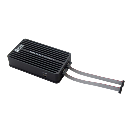
Infineon DAP/DAPE II Infineon DAP/DAPE II Active Probe - Enables debugging, tracing and testing of Infineon’s AURIX™ microcontroller family. It supports DAP and DAPE debug interface operating at their maximum frequency. Its small and compact hardware size allows for connecting to a target microcontroller in a confined space as far as 10 m away. -
Page 5: Important Safety Notice
Important safety notice General safety instructions - Please read the following safety precautions carefully before putting this device to use to avoid any personal injuries, damage to the instrument, or to the target system. Use this instrument only for its intended purpose as specified by this manual to prevent potential hazards. -
Page 6: Package Content
Package content The Infineon DAP/DAPE II Active Probe kit is delivered with the following components: Infineon DAP/DAPE II Two 10-pin 1.27mm 10cm 1m FNet Active Probe long ribbon cables Cable Ordering code: Ordering code: Ordering code: IC57163-1 IA10PIN10PIN127-AP BB-FNET-100 User Manual... -
Page 7: Specifications
Specifications GENERAL Supply voltage 9.0V DC via FNet cable Operating temperature 10°C to 40°C Storage temperature -10°C to 60°C Humidity 5% to 80% RH MECHANICAL Size 95 x 55 x 20 mm Weight 0.155 kg OPERATION Communication iSYSTEM proprietary FNet interface to BlueBox Debug signal valid 5.0 V (max. -
Page 8: Operation
Operation Device overview A – 10-pin DAP connector, with the following pinout: Signal Signal Signal Description Signal Signal Signal Description Direction Direction Reference Voltage Vref DAP1 DAP Data Ground DAP0 DAP Clock Ground DAP2 Optional 2nd Data Pin nTRST/DAP Not Connected Optional 3rd Data Pin Ground nRESET... - Page 9 Permanently green – Powered on and ready to use. Blinking green – Establishing connection with the BlueBox. Blinking blue – Reprogramming SPLASH. Permanently magenta – Golden image loaded and ready to use. D – mDIO port with the marked Pin1 on the housing mDIO port provides two digital signals, which can interact with the embedded target.
-
Page 10: Recommended Target Debug Connectors And Position
Recommended Target Debug Connectors and Position The target debug connector is a 10-pin, 1.27mm, double-row connector (e.g. Samtec FTSH- 105-01-L-DV,Samtec FTSH-105-01-L-DV-K with Keying Shroud). 1. Use the target debug connector(s) with the Keying Shroud option since incorrect connection can cause damage to the hardware. 2. -
Page 11: Mdio Cable
mDIO cable Ordering code BB-AP-MDIO-20 mDIO Cable is used to connect the Active Probe mDIO port with the signals around the debugged microcontroller, which can then be either read or controlled by the debugger. For example, the debugger can periodically service an external watchdog through the mDIO output or just read and record an external signal through the mDIO input. -
Page 12: Ecu14 Dap 10-Pin 1.27Mm Converter
ECU14 DAP 10-pin 1.27mm Converter Ordering code IADAP10ECU14 The ECU14 connector and the pinout has been defined by Bosch. The ECU14 DAP 10-pin converter is connecting at the end of the 10-pin 1.27mm Infineon DAP2 Wide D. Adapter (Ordering code IC50163-2) or Infineon DAP/DAPE II Active Probe (Ordering code IC57163-1) acting as a pinout converter is available for TriCore embedded targets... -
Page 13: Medc17 Dap 10-Pin 1.27Mm Converter
MEDC17 DAP 10-pin 1.27mm Converter Ordering code IADAP10MEDC17 The MEDC17 converter and the pinout has been defined by Bosch. Converter is connected at the end of the 10-pin 1.27mm Infineon DAP2 Wide D. Adapter (Ordering code IC50163-2) or Infineon DAP/DAPE II Active Probe (Ordering code IC57163-1) acting as a pinout converter and is available for TriCore embedded targets featuring the MEDC17 10-pin 1.27mm target debug connector. -
Page 14: 10-Pin Dap2 To 22-Pin Erf8 Dap2 Converter
10-pin DAP2 to 22-pin ERF8 DAP2 Converter Ordering code IA10PINDAP22PINSAM A converter connecting at the end of the 10-pin 1.27 mm DAP debug cable is available for Infineon 22-pin ERF8 Aurix pinout. This converter must be ordered separately. The following pinout is valid on the target side: Signal Signal Description Signal... -
Page 15: Dap 10-Pin 1.27Mm To Hstcu (Usb-C) Converter
DAP 10-pin 1.27mm to HSTCU (USB-C) Converter Ordering code IADAP10-HSTCU This converter is used to connect via 10-pin 1.27mm Infineon DAP2 Wide Debug Adapter (Ordering code: IC50163-2) or Infineon DAP/DAPE II Active Probe (Ordering code IC57163-1) to the USB-C target debug connector. The converter must be ordered separately. When attaching this converter to the Active Probe, make sure its marking A and marking B is aligned and matches with the markings on the Active Probe connector. - Page 16 The following pinout is valid on the target side: Signal Signal Signal Description Signal Signal Signal Description Direction Direction Ground Not Connected Not Connected Not Connected Not Connected Not Connected Not Connected Not Connected Target Reset Pin nRESET DAP1 DAP Data Optional 2nd DAP data DAP2 nTRST*...
-
Page 17: Active Probe And The Ic5700 Connecting Guidelines
Active Probe and the iC5700 Connecting Guidelines 1. Connect the iC5700 GND and the target GND using the Grounding wire. If the Grounding wire is not connected, the ground potential difference between the BlueBox hardware and the target can exceed well over 1000 V even before any of the devices are powered up. - Page 18 b. Place the connector without the shield of the 10-pin 1.27mm ribbon cable PARALLEL to the Target. c. Carefully push the 10-pin 1.27mm ribbon cable connector on the Target Debug Connector. Optionally, a longer ribbon cable can be ordered under the ordering code IA10PIN10P-AP- CUST.
-
Page 19: Setting Debug Interface Voltage Levels
Setting Debug Interface Voltage Levels The voltage levels for the debug interface are configured within winIDEA via Hardware menu / CPU Options / Hardware. When the microcontroller target supplies 5.0V to the Vref signal (pin 1), use the radio-button selection to select the Vref option instead. -
Page 20: Dap And Dape Configuration
DAP and DAPE configuration The Active Probe supports DAP interface or simultaneous DAP and DAPE interface at maximum DAP/DAPE frequency. Operational modes are: DAP Standard, a 2-pin DAP with single data line (default) or · DAP Wide, a 3-pin DAP with two data lines ·... -
Page 21: Further Active Probe Settings
Further Active Probe Settings The iC5700 is capable of connecting to AURIX™ target devices through one of the following: Its installed DTM module and an appropriate DAP cable adapter, e.g., 10-pin 1.27mm · Infineon DAP2 Wide D. Adapter, ordering code IC50163-2 or This debug system has limited maximum DAP frequency and the DAPE debug port is not supported. - Page 22 3. Click Refresh in Debug menu / Configure Session / SoCs / SoC and select the Active Probe. If you have only one Active Probe connected, you can leave the Active Probe selected and · winIDEA will automatically connect to an available Active Probe. If you have several Active Probes connected to your BlueBox, select the desired Active Probe ·...
-
Page 23: Accessories
Accessories IOM6 product line The functionality can be extended through the use of various modules from IOM6 product line. This enables various capabilities from parallel debugging of multiple targets, monitoring of network traffic and monitoring and manipulation of analog and digital signals. Ordering Code Description IC57031... - Page 24 iSYSTEM has made every effort to ensure the accuracy and reliability of the information provided in this document at the time of publishing. Whilst iSYSTEM reserves the right to make changes to its products and/or the specifications detailed herein, it does not make any representations or commitments to update this document.
Need help?
Do you have a question about the iSYSTEM Infineon DAP/DAPE II and is the answer not in the manual?
Questions and answers