Table of Contents
Advertisement
Quick Links
Advertisement
Table of Contents

Related Manuals for TASKING iSYSTEM Infineon AGBT


Summary of Contents for TASKING iSYSTEM Infineon AGBT
- Page 1 Infineon AGBT Active Probe User Manual V2.9, June 2023 isystem.com/start...
- Page 2 General safety instructions Please read the following safety precautions carefully before putting this device to use to avoid any personal injuries, damage to the instrument, or to the target system. Use this instrument only for its intended purpose as specified by this manual to prevent potential hazards. Use included power cord and power supply The enclosed power supply has been approved for use by iSYSTEM.
-
Page 3: Table Of Contents
Contents Package content ..........................4 Specifications ............................5 Operation ............................... 6 mDIO Cable ..............................8 10-pin 1.27 mm DAP Adapter ....................... 9 16-pin 2.54 mm JTAG Adapter ......................10 Samtec22 to HSTCU (USB-C) Converter ................... 11 Hardware Setup and Configuration ..................13 Accessories ............................ -
Page 4: Package Content
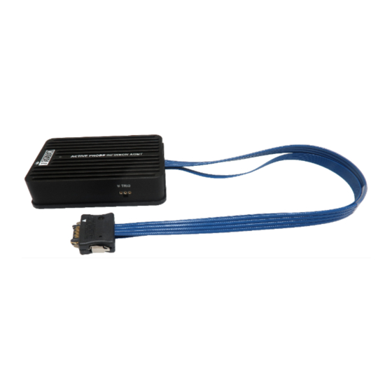
Package content Infineon AGBT Active Probe enables debugging, tracing and testing of all Infineon AURIX™ TC2xx, TC3xx (2nd generation), TC4xx (3rd generation) microcontrollers. It supports the DAP and Aurora GigaBit Trace (AGBT) interface operating at their maximum frequency. Its small and compact hardware size allows for connecting to a target microcontroller in a confined space as far as 10 m away. -
Page 5: Specifications
Specifications GENERAL Supply voltage 9.0V DC via FNet cable Operating temperature 10°C to 40°C Storage temperature -10°C to 60°C Humidity 5% to 80% RH MECHANICAL Size 80 x 55 x 18 mm Weight 0.125 kg OPERATION Communication iSYSTEM proprietary FNet interface to BlueBox Debug signal valid 5.0V (max. -
Page 6: Operation
Operation A – Samtec 22-pin ERF8 connector, with the following pinout: Signal Signal Signal Description Signal Signal Signal Description Direction Direction AGBT TX0_P TX0+ Vref Reference Voltage AGBT TX0_N TX0- DAP0 DAP Clock Ground DAP1 DAP Data AGBT TX1_P* TX1+ Not Connected AGBT TX1_N* TX1-... - Page 7 B – mDIO port marked as TRIG on the housing mDIO port provides two digital signals, which can interact with the embedded target. Each can be configured either for input or output operation. Number Name Pin1 IOØ Pin2 Pin3 mDIO port on the Active Probe mDIO port pinout C –...
-
Page 8: Mdio Cable
mDIO Cable Ordering code BB-AP-MDIO-20 mDIO Cable is used to connect the Active Probe mDIO port with the signals around the debugged microcontroller, which can then be either read or controlled by the debugger. For example, the debugger can periodically service an external watchdog through the mDIO output or just read and record an external signal through the mDIO input. -
Page 9: 10-Pin 1.27 Mm Dap Adapter
10-pin 1.27 mm DAP Adapter Ordering code IASAM22TRICOREPIN10-1 Infineon TriCore target can also feature a standard 10-pin 1.27mm DAP target debug connector exposing only the debug interface without the AGBT interface. The Active Probe can be used to connect to such targets through a small adapter connecting at the end of Samtec 22-pin ERF8 connector. -
Page 10: 16-Pin 2.54 Mm Jtag Adapter
16-pin 2.54 mm JTAG Adapter Ordering code IASAM22TRICOREPIN16 This adapter must be ordered separately to connect to the target featuring 16-pin 2.54 mm pitch JTAG target debug connector. The adapter is used only in conjunction with iSYSTEM solutions supporting Infineon AGBT trace interface (e.g. Infineon AGBT Active Probe ). The following pinout is valid on the target side: Signal Signal... -
Page 11: Samtec22 To Hstcu (Usb-C) Converter
Samtec22 to HSTCU (USB-C) Converter Ordering code IASAM22-HSTCU This converter is used to connect Infineon AGBT Active Probe (Ordering code: IC57164) to the TriBoards with HSTCU (High Speed Tool Connector USB-C). It must be ordered separately. When attaching this converter to the Active Probe, make sure its marking A and marking B is aligned and matches with the markings on the Active Probe connector. - Page 12 The following pinout is valid on the target side: Signal Signal Signal Description Signal Signal Signal Description Direction Direction Ground Not Connected AGBT TX0_P TX0+ CLK+ AGBT Clock AGBT TX0_N TX0- CLK- AGBT Clock Not Connected Not Connected Target Reset Pin nRESET DAP1 DAP Data...
-
Page 13: Hardware Setup And Configuration
Hardware Setup and Configuration For detailed visual presentation of the hardware setup and configuration, refer to Getting started tutorial. Use short link isystem.com/getting-started. 1. Connect the power supply cable. BlueBox should be switched off. 2. First connect via USB. Later you can configure TCP/IP connection to work remotely. 3. -
Page 14: Accessories
Accessories Analog/Digital and Network Trace Ordering Code Description IC57031 IOM6 Hub (3 x FNet & FBridge) IC57040 IOM6 CAN/LIN IC57041 IOM6 ADIO IC57125-1 ARM HSSTP II Active Probe IC57163-1 Infineon DAP/DAPE II Active Probe IC57164 Infineon AGBT Active Probe IC57150 MPC5x/SPC5x Aurora Active Probe IC57166 Infineon SGBT (HSTCU) Active Probe... -
Page 15: User Notes
User Notes This page is intentionally left blank. - Page 16 Visit our website for: Support - isystem.com/support · Tutorials - isystem.com/getting-started · Knowledge Base - kb.isystem.com · www.isystem.com...
Need help?
Do you have a question about the iSYSTEM Infineon AGBT and is the answer not in the manual?
Questions and answers