Advertisement
Quick Links
Advertisement

Related Manuals for TASKING iSYSTEM iC5000 BlueBox


Summary of Contents for TASKING iSYSTEM iC5000 BlueBox
- Page 1 iC5000 BlueBox Hardware User Manual V1.8, November 2023 isystem.com/start...
- Page 2 General safety instructions Please read the following safety precautions carefully before putting this device to use to avoid any personal injuries, damage to the instrument, or to the target system. Use this instrument only for its intended purpose as specified by this manual to prevent potential hazards. Use included power cord and power supply The enclosed power supply has been approved for use by iSYSTEM.
-
Page 3: Table Of Contents
Contents Package content ..........................4 Specifications ............................5 Device description ..........................6 Hardware Setup and Configuration ..................9 Accessories ............................10 Declarations ............................11... -
Page 4: Package Content
Package content iC5000 BlueBox On-Chip Analyzer is a hardware and software platform designed for debugging and testing a wide range of embedded microcontroller platforms that are based on a variety of processor architectures. Functionality can be further extended with the addition of the I/O Mod- ule, enabling the synchronous capture of analog and digital signals in parallel to trace informa- tion. -
Page 5: Specifications
Specifications GENERAL Operating temperature 10°C to 40°C Storage temperature -10°C to 60°C Humidity 5% to 80% RH MECHANICAL Size 122 x 127 x 45 mm (W x D x H) Weight approx. 500g OPERATION Communication inter- USB 2.0, 10/100 Mbps Ethernet faces to PC Supply voltage 10V to 24V DC... -
Page 6: Device Description
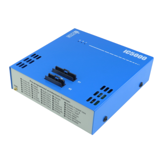
Device description... - Page 7 A – Two connectors, marked #1 and #2. These connectors are the interface to the target micro- controller. Depending on the target microcontroller debug features, the supplied ribbon-cables will need to be connected to either connector #1 only or connectors #1 and #2. B –...
- Page 8 F – 10/100 Ethernet Socket G – USB 2.0 Socket Recommended to use the USB 2.0 cable. The USB 2.0 interface provides the highest possible data transfer rate of the two available interfaces. Use of alternate cables must be undertaken at your own risk.
-
Page 9: Hardware Setup And Configuration
Hardware Setup and Configuration For detailed visual presentation of the hardware setup and configuration, refer to the Getting started tutorial - use the link isystem.com/start. 1. Connect the power supply cable. BlueBox should be switched off. 2. First connect via USB. Later you can configure TCP/IP connection to work remotely. 3. -
Page 10: Accessories
Accessories Various debug adapters are available to connect the iC5000 to a wide range target debug con- nector as commonly found on microcontroller development boards. More information about our products on www.isystem.com or via sales@isystem.com. -
Page 11: Declarations
Declarations EU Declaration of Conformity (DoC) iSYSTEM AG für Informatiksysteme Carl-Zeiss-Str. 1, 85247 Schwabhausen Germany declare that the DoC is issued under our sole responsibility and belongs to the following product: BlueBox debugger and analyzer solution Type: iC3000, iC5000, iC5500, iC5700, iC6000, iTAG.2K Identification allowing traceability: Object of the declaration is identified by a product type and unique serial number for each indi- vidual device. - Page 12 Visit our website for: · Support - isystem.com/support · Tutorials - isystem.com/start · Knowledge Base - kb.isystem.com www.isystem.com...
Need help?
Do you have a question about the iSYSTEM iC5000 BlueBox and is the answer not in the manual?
Questions and answers