Table of Contents
Advertisement
Quick Links
Advertisement
Table of Contents

Related Manuals for TASKING Infineon AGBT


Summary of Contents for TASKING Infineon AGBT
- Page 1 INFINEON AGBT ACTIVE PROBE HARDWARE USER MANUAL V3.2, May 2024 www.tasking.com...
- Page 2 Use included power cord and power supply The enclosed power supply has been approved for use by TASKING. Please contact TASKING if you need to consider an alternative power.
-
Page 3: Table Of Contents
Device description .................... 6 mDIO Cable ......................8 10-pin 1.27 mm DAP Adapter ................. 9 16-pin 2.54 mm JTAG Adapter ................10 Samtec22 to HSTCU (USB-C) Converter ..............11 Hardware Setup and Configuration .............. 13 Accessories ....................14 User Notes ...................... 15 www.tasking.com... -
Page 4: Package Content
Ordering code with IC5700: IC57164 BB-FNET-100 The Infineon AGBT Active Probe kit can be delivered with longer cable, i.e. 62 cm in length which allows you to connect to more difficult accessible Targets. Note that a longer cable can affect speed capabilities. Ordering code: IC57164-62. -
Page 5: Specifications
AGBT lanes Maximum AGBT bitrate 5Gbps AGBT clock source Active Probe options PROTECTION Debug signals 33 Ohm series termination/protection resistors, ESD protection devices DAP1-3 10k Ohm pull-down DAP_RESET 1k Ohm pull-up, 33 series termination/protection resistor VREF 1k Ohm input impedance www.tasking.com... -
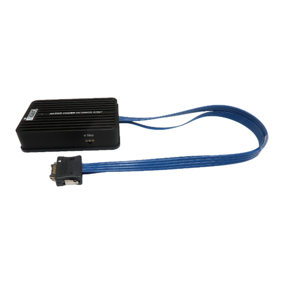
Page 6: Device Description
AGBT lanes. Blue colored signals are trace signals. Signal direction definition: O - Output from the Active Probe to the target microcontroller I - Input to the Active Probe from the target microcontroller www.tasking.com... - Page 7 Use only original accessories for powering and connecting with the BlueBox. Consult with technical support before attempting to use any other accessory. Target connector The target should feature a matching part, for example, Samtec part number: ASP-137969-01 (Samtec Series ERF8, Rugged High-Speed Socket). www.tasking.com...
-
Page 8: Mdio Cable
It must be ordered separately. Length of the cable is 20 cm. The following pinout is valid on the Active Probe side: Number Name Color Pin1 IOØ White Pin2 Brown Pin3 Black mDIO Cable pinout www.tasking.com... -
Page 9: 10-Pin 1.27 Mm Dap Adapter
Using the BlueBox at lower debug frequency scan speeds without trace functionality may be an acceptable compromise. You should test the BlueBox with a custom-length ribbon cable to ensure compatibility with winIDEA. www.tasking.com... -
Page 10: 16-Pin 2.54 Mm Jtag Adapter
This adapter must be ordered separately to connect to the target featuring 16-pin 2.54 mm pitch JTAG target debug connector. The adapter is used only in conjunction with TASKING solutions supporting Infineon AGBT trace interface (e.g. Infineon AGBT Active Probe ). -
Page 11: Samtec22 To Hstcu (Usb-C) Converter
Ordering code IASAM22-HSTCU This converter is used to connect Infineon AGBT Active Probe to the TriBoards with HSTCU (High Speed Tool Connector USB-C). It must be ordered separately. When attaching this converter to the Active Probe, make sure its marking A and marking B is aligned and matches with the markings on the Active Probe connector. - Page 12 (HSTCU) USB-C pinout Blue colored signals are trace signals. Signal Direction is described from the BlueBox perspective. When initially connecting the BlueBox to a target, ensure the debug adapter pinout matches the Target connector to avoid potential hardware failure. www.tasking.com...
-
Page 13: Hardware Setup And Configuration
7. Install winIDEA and create a new workspace. 8. Configure Debug channel modes via Hardware / CPU Options / SoC. For troubleshooting refer to Knowledge Base - use the link kb.isystem.com. More general settings are described in winIDEA Help. www.tasking.com... -
Page 14: Accessories
MPC5x/SPC5x Aurora Active Probe IC71150 or IC57150 Infineon SGBT (HSTCU) Active Probe IC71166 or IC57166 RH850 Aurora Active Probe IC71176 or IC57176 Infineon AGBT USB-C Active Probe Accessories Description Ordering Code 10-pin 1.27 mm DAP Adapter IASAM22TRICOREPIN10-1 16-pin 2.54 mm JTAG Adapter IASAM22TRICOREPIN16 1.0m FNet Cable... -
Page 15: User Notes
User Notes This page is intentionally left blank. www.tasking.com... - Page 16 Visit our website for: · Support - isystem.com/support · Tutorials - isystem.com/start · Knowledge Base - kb.isystem.com www.tasking.com www.tasking.com...
Need help?
Do you have a question about the Infineon AGBT and is the answer not in the manual?
Questions and answers