
Related Manuals for TASKING INFINEON DAP


Summary of Contents for TASKING INFINEON DAP
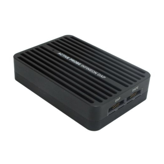
- Page 1 INFINEON DAP/DAPE ACTIVE PROBE HARDWARE USER MANUAL V3.5, March 2024 www.tasking.com...
- Page 2 Use included power cord and power supply The enclosed power supply has been approved for use by TASKING. Please contact TASKING if you need to consider an alternative power.
-
Page 3: Table Of Contents
ECU14 DAP 10-pin 1.27mm Converter ..............9 MEDC17 DAP 10-pin 1.27mm Converter ..............10 10-pin DAP2 to 22-pin ERF8 DAP2 Converter ............11 DAP 10-pin 1.27 to HSTCU (USB-C) Converter ............12 Hardware Setup and Configuration .............. 14 Accessories ....................15 www.tasking.com... -
Page 4: Package Content
Package content The Infineon DAP/DAPE Active Probe kit is delivered with the following components: Infineon DAP/DAPE Two 10-pin 1.27mm 10cm long 1m FNet Active Probe ribbon cables Micro Cable Ordering code: Ordering code: Ordering code: IC57163 IA10PIN10PIN127-AP BB-FNETMICRO-100 www.tasking.com... -
Page 5: Specifications
Power consumption Max. 1.5W (dependent on operation mode) PROTECTION Debug signals 33 Ohm series termination/protection resistors, ESD protection devices DAP1-3 and DAPE1-3 10k Ohm pull-down DAP_RESET 1k Ohm pull-up, 33 series termination/protection resistor VREF 1k Ohm input impedance www.tasking.com... -
Page 6: Device Description
Signal Dir- Signal Description Signal Signal Signal Description ection ection Reference Voltage Vref DAPE1 DAP Data Ground DAPE0 DAP Clock Ground DAPE2 Optional 2nd Data Pin DAPEN/DAP Not Connected Optional 3rd Data Pin Ground Not Connected 10-pin DAPE pinout www.tasking.com... - Page 7 When powering on the system, switch the iC5700 on before powering on the target sys- tem. When powering down the system, power off the target before powering off the iC5700! Use only original TASKING accessories for powering and connecting with the iC5700. Consult with TASKING before attempting to use any other accessory. www.tasking.com...
-
Page 8: Recommended Target Debug Connectors And Position
DAP connector when looking from the edge of the PCB. The connectors must be at least 11.0 mm apart, although a distance of 16.8 mm is recommended. The goal should be to link the Active Probe to the target hardware via non-twisted and, when DAPE is used, parallel ribbon cables. www.tasking.com... -
Page 9: Ecu14 Dap 10-Pin 1.27Mm Converter
10-pin 1.27mm Infineon DAP2 Wide D. Adapter (Ordering code IC50163-2) or Infineon DAP/DAPE II Active Probe (Ordering code IC57163-1) acting as a pinout converter is available for TriCore targets featuring the ECU14 10-pin 1.27mm target debug con- nector. -
Page 10: Medc17 Dap 10-Pin 1.27Mm Converter
The pin next to the alignment pin is pin 10 and not pin 1! Pin is marked with a number 1 directly on the converter target connector. The converter connects to the target via a 10-pin 1.27mm connector, Samtec SFM-105-02-L-D-A. A target should feature a matching part, for example Samtec TFM-105-02-L-D. www.tasking.com... -
Page 11: 10-Pin Dap2 To 22-Pin Erf8 Dap2 Converter
The debug adapter connects to the target via a 22-pin ERF8 connector, Samtec ASP-137971-02. The target must have populated a matching part, for example Samtec ASP-137969-01, Samtec Series ERF8, Rugged High Speed Socket. www.tasking.com... -
Page 12: Dap 10-Pin 1.27 To Hstcu (Usb-C) Converter
IADAP10-HSTCU This converter is used to connect via 10-pin 1.27mm Infineon DAP2 Wide Debug Adapter (Ordering code IC50163-2) or Infineon DAP/DAPE II Active Probe (Ordering code IC57163-1) to the USB-C target debug connector. The converter must be ordered separately. When attaching this converter to the Active Probe, make sure its marking A and marking B is aligned and matches with the markings on the Active Probe connector. - Page 13 When initially connecting the BlueBox to a target, ensure the debug adapter pinout matches the Target connector to avoid potential hardware failure. Make sure this adapter fits on your target connector - use link isystem.com/cross-table for more information. Use link isystem/connect to get more information on how to connect the hardware. www.tasking.com...
-
Page 14: Hardware Setup And Configuration
Although it looks similar to the HDMI interface, the FNet Port is not compatible with HDMI or any HDMI accessories. Connecting TASKING hardware to HDMI accessories will damage the hardware and will render the TASKING hardware warranty void. 5. Allocate the pin 1 on the Target and the ribbon cable connector. -
Page 15: Accessories
BB-FNETMICRO-100 1.0m FNet Micro Cable (Active Probe) BB-FNETMICRO-300 3.0m FNet Micro Cable (Active Probe) BB-FNETMICRO-500 5.0m FNet Micro Cable (Active Probe) Please refer to the iC5700 BlueBox for all current iC5700 accessories. More information about our products via sales@tasking.com. www.tasking.com... - Page 16 Visit our website for: · Support - isystem.com/support · Tutorials - isystem.com/start · Knowledge Base - kb.isystem.com www.tasking.com www.tasking.com...
Need help?
Do you have a question about the INFINEON DAP and is the answer not in the manual?
Questions and answers