
Related Manuals for Thermo Scientific Sorvall X Pro Series


Summary of Contents for Thermo Scientific Sorvall X Pro Series
- Page 1 Thermo Scientific Sorvall X Pro / ST Plus Series Centrifuges Instructions for Use 50158527-d • 08 / 2019...
-
Page 2: Table Of Contents
Table of Contents Preface About this Manual Where Do I Find Information about my Centrifuge? Intended Use Signal Words and Symbols Symbols used on Unit and Accessories Symbols used in the Instructions for Use Safety Instructions 1. Transport and Set Up 1. - Page 3 2. 6. Identify Rotor and Buckets 2. 7. Set Basic Centrifugation Parameters 2. 8. Pre-Temper the Centrifugation Chamber 2-10 2. 9. Centrifugation 2-10 2. 10. Aerosol-Tight Applications 2-11 3. Graphical User Interface 3. 1. Overview 3. 2. Set Basic Centrifugation Parameters 3.
- Page 4 5. Maintenance and Care 5. 1. Cleaning Intervals 5. 2. Basics 5. 3. Cleaning 5. 4. Disinfection 5. 5. Decontamination 5. 6. Autoclaving 5. 7. Maintenance 5. 8. Shipping 5. 9. Storage 5. 10. Disposal 6. Troubleshooting 6. 1. Mechanical Emergency Door Release 6.
- Page 5 List of Figures Figure 1–1: Safety Zone � � � � � � � � � � � � � � � � � � � � � � � � � � � � � � � � � � � � � � � � � � � � � � � � � � � � � � � � � � � � � � � � � � � � � � 1-2 Figure 1–2: Lifting the Centrifuge at Both Sides �...
- Page 6 Figure 3–28: Home Screen with Alert Message � � � � � � � � � � � � � � � � � � � � � � � � � � � � � � � � � � � � � � � � � � � � � � � � � � 3-15 Figure 3–29: Status –...
- Page 7 Figure 4–8: Setting the Correct Bucket Code for the Rotor � � � � � � � � � � � � � � � � � � � � � � � � � � � � � � � � � � � � � � � � � � 4-5 Figure 5–1: Removing the ventilation grid �...
- Page 8 Table A–1: Technical Data Sorvall X Pro Series Centrifuges � � � � � � � � � � � � � � � � � � � � � � � � � � � � � � � �...
- Page 9 Table B–34: Accessories Fiberlite F14-6 x 250 LE Rotor � � � � � � � � � � � � � � � � � � � � � � � � � � � � � � � � � � � � � � � � � � � B-23 Table B–35: Technical Data Fiberlite F15-6 x 100y for Sorvall X4 Pro / X4 Pro-MD �...
-
Page 10: About This Manual
ƒ Where Do I Find Information about my Centrifuge? This manual covers multiple Thermo Scientific Sorvall X Pro / ST Plus Series centrifuge models. You can identify your centrifuge model by gathering two items of information: the product series from the front panel—for example, Thermo Scientific Sorvall X Pro Series ƒ... -
Page 11: Signal Words And Symbols
75009526 Sorvall ST4R Plus-MD 100 V ±10%, 50 / 60 Hz 100 V ±10%, 50 / 60 Hz Table i: List of Thermo Scientific Centrifuges Signal Words and Symbols Signal Word and Colors Degree of Hazard WA R NI NG Indicates a hazardous situation that, if not avoided, could result in death or serious injury. -
Page 12: Symbols Used On Unit And Accessories
Preface Symbols used on Unit and Accessories Observe the information contained in the instructions for use to keep yourself and your environment safe. General hazard Refer to instruction manual Biological hazard Disconnect mains plug Danger of cuts Direction of rotation Make sure the rotor is installed properly by lifting it slightly at the handle. - Page 13 Preface Risk from handling hazardous substances. When working with corrosive samples (salt solutions, acids, bases), the accessories and the centrifuge have to be cleaned thoroughly. WA R NI NG Extreme care should be taken with highly corrosive substances that can cause damage and impair the mechanical stability of the rotor.
- Page 14 Preface Cutting injuries from broken display glass. Do not touch a damaged display. C A U T IO N Safety can be impaired by wrong loading and worn accessories. Always make sure that the load is as equally distributed as possible. Do not use rotors and accessories which show any signs of corrosion or cracks.
-
Page 15: Transport And Set Up
Please note that the centrifuge is supplied without a rotor. Rotors and items supplied with rotors are listed in the chapter “Rotor Specifications” on page B-1. Item Art. No. Quantity Thermo Scientific Centrifuge Power Supply Cable Printed Instructions for Use 50158487 Instructions for Use on USB 50158526... -
Page 16: Transporting
Transport and Set Up The set up location must be well ventilated at all times. ƒ The main switch and power supply plug must be easily accessible at all times. The grounded electrical ƒ socket should be well accesible and located outside of the safety zone. Figure 1–1: Safety Zone 1. -
Page 17: Product Overview
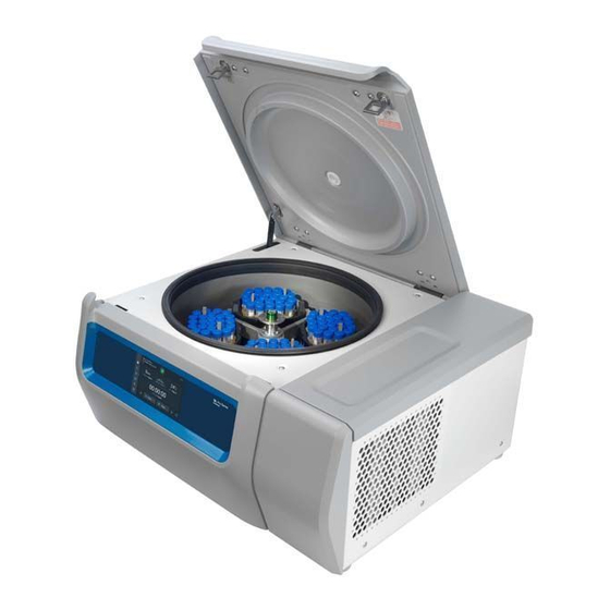
Transport and Set Up 1. 4. Product Overview 1. 4. 1. Refrigerated Benchtop Centrifuges With Graphical User Interface (GUI) Front Back ➀ ➁ ➂ ➃ ➄ USB; RS232; Ethernet; Mains Connection; Power Supply Switch Figure 1–3: Product overview refrigerated benchtop centrifuge with GUI With LCD Control Panel Front Back... -
Page 18: Figure 1-5: Product Overview Ventilated Benchtop Centrifuge With Gui
Transport and Set Up 1. 4. 2. Ventilated Benchtop Centrifuges With Graphical User Interface Front Back ➀ USB; ➁ RS232; ➂ Ethernet; ➃ Mains Connection; ➄ Power Supply Switch Figure 1–5: Product overview ventilated benchtop centrifuge with GUI With LCD Control Panel Front Back ➀... -
Page 19: Connections
Transport and Set Up 1. 5. Connections 1. 5. 1. Mains Connection Connect the centrifuge into grounded electrical sockets only. NOTI CE Turn off the power supply switch. Make sure that the power supply cable specification agrees with the safety standards of your country. Make sure that the voltage and frequency are the same as the figures on the nameplate. -
Page 20: Operation
Operation 2. Operation 2. 1. Position of parts Particle Deflection Seal; Gas spring; Centrifugation chamber; User Interface; ➀ ➁ ➂ ➃ Centrifuge lid; ➅ Drive shaft ➄ Figure 2–1: Position of centrifuge parts shown on a ventilated centrifuge with LCD control panel Rotor body;... -
Page 21: Figure 2-3: Position Of Rotor Parts Shown On A Swing Out Rotor
Operation Bucket; Cap latch; Bucket cap; Rotor knob; Auto-Lock button; Rotor ➀ ➁ ➂ ➃ ➄ ➅ cross Figure 2–3: Position of rotor parts shown on a swing out rotor Rotor lid; Auto-Lock button; Rotor lid knob; Rotor cross with buckets within ➀... -
Page 22: Power On/Off The Centrifuge
Operation 2. 2. Power on/off the Centrifuge Figure 2–5: Rear view of the centrifuge, position of the mains switch To power on the centrifuge: Push on the mains switch of the centrifuge to “1” to power it on. When the centrifuge has completed booting it is ready for operation. Once you have started running the centrifuge with your own parameters, it will show the settings from the last session after powering up. -
Page 23: Figure 2-6: Put On/Off The Rotor Lid
Operation Rotor lid installation: Put the rotor lid on the rotor. Make sure the rotor lid is put centered on the rotor. Figure 2–6: Put on/off the rotor lid b. Turn the rotor knob clockwise to close the rotor. Turn it counter-clockwise to open rotor. There is no need to press the Auto-Lock key to close or open the rotor. -
Page 24: Figure 2-8: Pressing The Auto-Lock Key
A-8. Operate the centrifuge only with rotors and accessories from this list. Make sure that all components of a rotor are safely fixed when carried. The centrifuge is equipped with a Thermo Scientific™ Auto-Lock™ locking feature that automatically locks the rotor to the drive shaft. -
Page 25: Load The Rotor
Operation 2. 5. Load the Rotor 2. 5. 1. Loading Load the compartments evenly. Balance opposite loads. When using swing out rotors mind the following in addition: Weigh the bucket content (adapter and tube). Make sure you do not exceed the maximum compartment ƒ... - Page 26 Operation Before loading a Rotor Inspect the rotor and all accessory parts for damage, such as cracks, scratches, or traces of corrosion. Inspect the centrifugation chamber, drive shaft and Auto-Lock device for damage, such as cracks, scratches, or traces of corrosion. Check the suitability of the rotor and other used accessories against the Chemical Compatibility Chart.
-
Page 27: Identify Rotor And Buckets
Operation RCF Value Explained The relative centrifugal force (RCF) is given as a multiple of the force of gravity (g). It is a unitless numerical value which is used to compare the separation or sedimentation capacity of various centrifuges, since it is independent of the type of device. Only the centrifuging radius and the speed are used for calculation: r = centrifuging radius in cm n = rotational speed in rpm... -
Page 28: Set Basic Centrifugation Parameters
Operation To identify buckets using a centrifuge with a LCD control panel: Bucket selection is only possible for swing-out rotors. The bucket code corresponds to the last four digits of the bucket article number. Proceed as follows to select the bucket type installed in the rotor: Press the + or - button below the “Bucket”... -
Page 29: Pre-Temper The Centrifugation Chamber
Operation Set Temperature A refrigerated centrifuge allows for preselecting a temperature for the sample (GUI versions) or centrifugation chamber temperature (LCD control panel) between -10 °C and +40 °C for the centrifugation run. This feature is not available on ventilated models. 2. 8. Pre-Temper the Centrifugation Chamber Refrigerated centrifuges allow for pre-tempering, that is pre-warming or pre-cooling, the centrifugation chamber and the empty rotor before the centrifugation run starts. -
Page 30: Aerosol-Tight Applications
Operation 2. 10. Aerosol-Tight Applications 2. 10. 1. Basic Principles Make sure that the sample containers are well suited for the desired centrifugation process. Aerosol-tight rotors and tubes may only be opened in an approved safety CAUT I ON work-bench when centrifuging dangerous samples. Mind the maximum permissible load. -
Page 31: Figure 2-17: Bucket With Open Lid (Left) And Closed Lid (Right)
Operation 2. 10. 4. Aerosol-Tight Rotor Buckets Aerosol-tight Closure with ClickSeal If neccessary, grease the lid joint before closing the lid. Use grease (76003500) for this. Raise the latch. The cap can now be easily placed on the bucket. Lower the latch to close the bucket aerosol-tight; be sure the latch clicks into place. Make sure that both sides of the latch are closing the bucket cap. - Page 32 Operation CAUTION Prior to each use, the seals in the rotor are to be inspected in order to assure that they are correctly seated and are not worn or damaged. Damaged seals are to be replaced immediately. Replacement seals can be re-ordered as a spare part (“Rotor Specifications”...
-
Page 33: Graphical User Interface
Graphical User Interface 3. Graphical User Interface This chapter contains details for centrifuges with the graphical user interface described in this manual. Pictures shown are examples and may be different in details to your experience – for example the home screen for a ventilated unit does not feature an on-screen button entry for entering temperature. -
Page 34: Figure 3-3: Touchscreen Display For Refrigerated Centrifuge
Graphical User Interface Figure 3–3: Touchscreen Display for Refrigerated Centrifuge Info & Health Status Area (Region 1) The “Info & Health Status” area at the top of the display window appears in all screen displays. Figure 3–4 shows an example of the “Info & Health Status” area on a unit that is in proper working condition. Figure 3–4: Info &... -
Page 35: Figure 3-5: Home Screen For Idle Centrifuge
Graphical User Interface Home Screen Figure 3–5 shows the “Home” screen and its icon in the navigation bar. The “Home” screen is the default screen from where you run all routine centrifuge operations. It has touch- sensitive fields and buttons that let you set speed, runtime, pre-tempering target temperature (refrigerated models only), start and stop the centrifuge, as well as open the lid. -
Page 36: Figure 3-8: Settings Main Screen
Graphical User Interface The Home button opens the “Home” screen shown in Figure 3–6 Figure 3–7. The speed box shows the current speed (top) and the speed setpoint (bottom) for the ongoing or upcoming centrifugation run. Tapping the speed box lets you set the speed setpoint and toggle the unit between rpm and x g. -
Page 37: Figure 3-9: Control Panel For Ventilated Centrifuge
Graphical User Interface Control Panel (Region R2B) The “Control Panel” in Screen Region R2B contains a complete set of controls for operating the functions of the centrifuge. The inventory of buttons varies with the number of options built into the unit, as can be seen in Figure 3–9 Figure 3–10. -
Page 38: Set Basic Centrifugation Parameters
Graphical User Interface ➀ Navigation bar visible ➁ Navigation bar hidden ➂ Show/Hide arrow button Figure 3–11: Navigation bar The navigation bar has the following icons: Icon Function Back button: In multi-level menus, lets you run backwards through all screens previously displayed. -
Page 39: Figure 3-12: Speed Box On Home Screen
Graphical User Interface RCF Value Explained The relative centrifugal force (RCF) is given as a multiple of the force of gravity (g). It is a unitless numerical value which is used to compare the separation or sedimentation capacity of various centrifuges, since it is independent of the type of device. -
Page 40: Figure 3-15: Setpoints Screen Detail For Centrifuge Speed, And Range
Graphical User Interface Tap the rpm or x g radio button to toggle between speed (in rpm, which is short for revolutions per minute) and RCF (in x g, which means multiples of the force of gravity). Figure 3–15: Setpoints Screen Detail for Centrifuge Speed, and Range Tap in the Speed entry field shown in Figure 3–15, then use the keypad on the right to enter the desired... -
Page 41: Figure 3-19: Run Time Box On Home Screen
Graphical User Interface Run Time in Standard Mode Tap in the Time entry field above and use the keypad shown to enter the desired run time period. Run time is shown in “hh:mm:ss”. For example, if you want to enter 2 hours and 30 min you must first tap “2”... -
Page 42: Figure 3-21: Temperature Box On Home Screen
Graphical User Interface 3. 2. 4. Set Temperature A refrigerated centrifuge allows for preselecting a temperature for the sample between -10 °C and +40 °C for the centrifugation run. This feature is not available on ventilated models. CAUTION Due to air friction the temperature of the rotor may rise significantly while the centrifuge is spinning. -
Page 43: Pre-Temper The Centrifugation Chamber
Graphical User Interface 3. 3. Pre-Temper the Centrifugation Chamber Refrigerated centrifuges allow for pre-tempering, that is pre-warming or pre-cooling, the centrifugation chamber and the empty rotor before the centrifugation run starts. If necessary pre-temper your samples using proper equipment. The centrifuge is not intended to be used to pre-temper your samples. NOTICE Ventilated models cannot pre-temper the centrifugation chamber. -
Page 44: Centrifugation
Graphical User Interface 3. 4. Centrifugation Mind the safety zone of minimum 30 cm around the centrifuge. Refer to “Info & Health Status Area” on page 3-2. Persons and hazardous substances must be kept out of this safety zone while centrifuging. Once the main switch has been turned on, the rotor has been properly installed, the setpoints have been set as explained in the previous section, and the centrifuge lid has been closed, you are ready to start. -
Page 45: Figure 3-25: Pulse Mode: Centrifuge Running For One Minute
Graphical User Interface Run in Pulse Mode Proceed as follows to use the unit for short-run centrifugation: Check the preset Pulse Mode button behavior displayed on the Pulse button whether it suits your needs. The different Pulse button behaviors are explained in the section “Pulse Customization”... -
Page 46: Status, Alarms And Alerts
Graphical User Interface 3. 5. Status, Alarms and Alerts This section explains how you can view current status information, alarms, and alerts using the buttons in the “Info & Health Status” area. Status When the centrifuge is in good health, the touchscreen display shows a green heart icon in the “Info & Health Status”... -
Page 47: Figure 3-27: Rotor End Of Life Alert Message On Top Of Home Screen
Graphical User Interface Alerts When a maintenance action becomes due or when a minor disturbance without any impact on the safe operation of the centrifuge occurs, the unit issues an alert. The centrifuge may continue to spin, but you must correct the root cause as soon as possible to avoid damage to the samples and/or the unit itself. -
Page 48: Figure 3-29: Status - Alert Screen With Alert List
Graphical User Interface Viewing and Handling Alerts Tapping the warning triangle icon in the “Info & Health Status” area of the touchscreen display opens the “Status – Alert” screen shown in Figure 3–29 below. This screen lists all alerts that are currently active. The latest alert appears expanded to let you view the full details. -
Page 49: Figure 3-31: Alarm Message On Top Of Home Screen
Graphical User Interface Tap the desired alert list item. The alert item is expanded to reveal the details. Solve the problem and acknowledge the alert, then tap the alert list item one more time to reduce it. Once you have solved and acknowledged all alerts, the “Status – Good Screen” appears to confirm that the centrifuge is free of alerts. -
Page 50: Figure 3-33: Full Screen Alarm Message
Graphical User Interface The visible buttons, such as Pre-Temp, Pulse, Start/Stop, and Lid Open, are still operable in this state, depending on whether centrifuge is still running or idle. For example, you can usually stop a running centrifuge and open the lid, or you can navigate to other screens using the left-hand navigation bar while alrams are present. -
Page 51: Figure 3-35: Status - Alarm Screen: Operating Details Expanded
Graphical User Interface Figure 3–35: Status – Alarm Screen: Operating Details Expanded NOTICE These status information fields show the same content as the “Status” screen, plus the rotor log. This is described in the sections “Status” on page 3-14 “Rotor Log” on page 3-47 , respectively. -
Page 52: Figure 3-37: Pristine Programs Screen (Prior To Creating Programs)
Graphical User Interface Automate Processes Using Programs To reduce the setup effort before a centrifugation run, the centrifuge lets you store up to 100 programs. Programs are pre-programmed centrifugation runs with a user-specified parameter set. Programs can consist of a single step that runs with just one parameter set, or of several steps with changing parameter sets. -
Page 53: Figure 3-39: Programs With Keypad Overlay
Graphical User Interface Figure 3–39: Programs with Keypad Overlay Enter a program name of maximum 20 characters length. Tap rpm or x g to choose the unit for centrifuge speed. Tap the Temp field and enter a target temperature for pre-tempering (refrigerated models only). Enter numbers for the acceleration and deceleration profiles, if desired (see “Settings ->... -
Page 54: Figure 3-42: Programs -> Advanced Settings Screen
Graphical User Interface Figure 3–41: Programs -> Add New Program Screen, Speed and Time for Step 1 12. If you wish to vary speed and run time during the centrifugation run, tap the + Add Step button. 13. Tap the Speed field and enter a different speed for Step 2. 14. -
Page 55: Figure 3-43: Programs -> Program Quick View Pop-Up Window
Graphical User Interface NOTICE Leaving this box unchecked will load the program onto the main screen, but will require an additional tap on the Start button on the “Home” screen. Previewing Program Parameters The main “Programs” screen allows you to preview the parameters of a program listed there, so you can see what it does before you run it. -
Page 56: Figure 3-45: Programs -> Delete Confirm Window For Program Step)
Graphical User Interface Figure 3–45: Programs -> Delete Confirm Window for Program Step) Tap Delete one more time to delete the step. When you have finished making changes, tap the Save button to save your changes. You will be returned to the main “Programs” screen. The program has been changed according to your entries. -
Page 57: Figure 3-47: Programs Screen With Pre-Stored User Programs
Graphical User Interface Running a Program Programs are run from the “Programs” screen shown in Figure 3–47. The “Programs” screen opens when you tap the “Programs” button from the navigation bar on the left side of the touchscreen display. You run an existing program by tapping on any of the user-named program buttons listed on the main “Programs” screen. -
Page 58: Figure 3-48: Programs -> Export Programs Screen
Graphical User Interface Figure 3–48: Programs -> Export Programs Screen The matching “Import Programs” screen is used for importing the programs on the target centrifuge. Figure 3–49: Programs -> Import Programs Screen Exporting Programs Proceed as follows to export one or more programs: Insert a USB drive with sufficient free storage space into the USB port of the centrifuge. -
Page 59: Figure 3-50: Programs -> Export Programs Pop-Up Window With Progress Bar
Graphical User Interface Figure 3–50: Programs -> Export Programs Pop-up Window with Progress Bar NOTICE You may abort a running export at any time by tapping the Cancel button in the “Export Programs” pop-up window shown in Figure 3–50 above. If you do so, the export is aborted, and the “Export Error“message appears. -
Page 60: Figure 3-52: Programs -> Import Programs Pop-Up Window With Progress Bar
Graphical User Interface Figure 3–52: Programs -> Import Programs Pop-up Window with Progress Bar NOTICE You may abort a running import at any time by tapping the Cancel button in the Import Programs pop-up window. If you do so, the import is aborted, and the Import Error message appears. This message lists all programs that have not been imported successfully. -
Page 61: Settings
Graphical User Interface 3. 6. Settings This section explains how to set up the centrifuge using the options of the Settings main screen. The “Settings Main” screen opens up when you tap the Settings icon in the navigation Bar and features eight buttons. - Page 62 Graphical User Interface Alarm Tone You may change the alarm tone for the front window directly on the main “Alarms Settings” screen by just tapping on the drop-down list labeled Alarm Tone and selecting one of the three options. NOTICE The naming of the options may differ in each country. Proceed as follows to change the Alarm Tone: Tap the Settings icon on the navigation bar.
-
Page 63: Figure 3-56: Settings -> Alerts Screen
Graphical User Interface 3. 6. 2. Alerts Tapping the Alerts button on the “Settings” screen takes you to the “Alerts Settings” screen. On the “Alerts Settings” screen, you may change the alert volume, tone, and behavior of status messages issued by the centrifuge. -
Page 64: Figure 3-58: Settings -> Access Control Screen
Graphical User Interface Alert Option Checkboxes There are three checkboxes on the “Alerts Settings” screen: Check or uncheck the “Display parameter settings” confirmations checkbox. By default, this checkbox is checked and will display a “Save” confirmation pop-up window each time you change a main setpoint parameter, including run time, temperature, speed, acceleration and deceleration profile. -
Page 65: Table 3-2: Passcode Login Requirements In Open And Secure Mode
Graphical User Interface Passcode Passcode Action Required in Open Required in Mode Secure Mode Set parameters and run the unit Run programs Create, edit, and delete programs Change display settings Change control settings Change alarm settings Change alert settings View and export event log Connect the unit to a wired network View Files and Info screen Snooze Alarms... -
Page 66: Figure 3-59: Settings -> Access Control: Access Control Screen In Secure Mode
Graphical User Interface Figure 3–59: Settings -> Access Control: Access Control Screen in Secure Mode Tap the Secure button in the “Access Control” screen. The passcode prompt appears, asking you to enter the current admin passcode. You will be returned to the “Access Control” window. The mode has changed from open to secure, and the Save button has turned blue to indicate that you may save your changes now. -
Page 67: Figure 3-60: Settings -> Controls -> Setpoints: Standard Screen For Refrigerated Centrifuge
Graphical User Interface In “Advanced Mode”, you can choose which timed mode the centrifuge runs in by default: ACE, Timed or Continuous. “Standard Mode” only allows for a timed setpoint. Table 3–3 lists the items on “Setpoints” screen and explains their respective functions. Field(s) Function Speed field: Lets you set a default setpoint for the speed box on the “Home”... -
Page 68: Figure 3-61: Settings -> Controls -> Setpoints: Advanced Screen For Ventilated Centrifuge
Graphical User Interface Figure 3–61: Settings -> Controls -> Setpoints: Advanced Screen for Ventilated Centrifuge Proceed as follows to customize the setpoints for Standard Mode and Advanced Mode: Tap the Settings icon on the navigation bar. Tap the Controls button on the “Settings”... - Page 69 Graphical User Interface To confirm the changes, tap the OK button in the pop-up window that appears. Tapping the X icon closes this window and exits without saving. You will be returned to the “Controls” screen. If you have chosen “Advanced Mode”, a click-wheel with “Timed Run” options will now be added to the screen that opens when you tap the Time box on the “Home”...
- Page 70 Graphical User Interface Proceed as follows to toggle between the auto-open and closed modes of the lid: Tap the Settings icon on the navigation bar. Tap the Controls button on the “Settings” screen. The “Controls” screen appears. Tap the Lid Auto Open menu and choose Yes to have the lid unlocked, or No to keep it closed (factory default).
- Page 71 Graphical User Interface NOTICE The AM/PM division does not appear when the radio button in the “Settings -> Display -> Time“ screen is set to 24hr (see “Time” on page 3-43 for details). Tap the Time On field and enter the time of day at which you wish the centrifuge to start. Tap the Temp field (refrigerated models only) and set the target temperature for pre-tempering, if desired.
-
Page 72: Figure 3-63: Settings -> Scheduling -Screen With All Schedules Disabled
Graphical User Interface Figure 3–63: Settings -> Scheduling -Screen with All Schedules Disabled Rotor Bucket The Rotor Bucket button takes you to the “Rotor Bucket” screen. The “Rotor Bucket” screen allows you to enable and set the default bucket selection for the rotor detection prompt (see “Identify Rotor and Buckets”... -
Page 73: Display
Graphical User Interface 3. 7. Display Tapping the Display button on the “Settings” screen takes you to the “Display” screen. The “Display” screen offers a stack of buttons. These buttons allow for customizing general display properties for all screens of the Graphical User Interface to suit your needs, altering the factory default settings. - Page 74 Graphical User Interface To confirm the changes, tap the OK button in the pop-up window that appears. Tapping the X icon closes this window and exits without saving. You will be returned to the “Display” screen. 3. 7. 2. Language The Language button on the “Display”...
- Page 75 Graphical User Interface The segments of the wheel picker screen are rearranged to reflect the selected date format. For example, if you select the DD/MM/YYYY radio button, the wheel picker will change to 28 | Jul | 2018. Tap the up/down arrows or swipe your finger up or down across the wheel to set the current month, day, and year on each of the three wheel picker segments.
-
Page 76: Logs
Graphical User Interface 3. 7. 7. Unit Name The Unit Name button opens the “Unit Name” screen, where you can set a name for the centrifuge that will be displayed above the time/date field in the “Info & Health Status” area on top of the “Home” screen. Proceed as follows to edit the name of the unit: Tap the Settings icon on the navigation bar. -
Page 77: Figure 3-67: Event Log Screen
Graphical User Interface 3. 8. 1. Event Log Tapping the Event Log button on the “Logs” main screen opens the “Event Log” screen shown in Figure 3–67 below. The “Event Log” screen lists the last 100 events logged by the centrifuge with their time of occurrence, including normal operating status as well as abnormal conditions, such as alarms. - Page 78 Graphical User Interface NOTICE The “View All” checkbox is deactivated automatically when you deactivate any of the other options. If you are not satisfied with the selection you have made, it may be helpful to tap “View All” and start over selecting. Tap anywhere outside the filter pop-up menu to return to the “Event Log”...
-
Page 79: Figure 3-69: Rotor Log Screen
Graphical User Interface 3. 8. 2. Rotor Log Tapping the Rotor Log button on the “Logs” main screen opens the “Rotor Log” screen. The “Rotor Log” screen keeps track of how many times individual rotor (bucket) types have been spun in the current centrifuge and issues warnings when a rotor reaches its end of life. -
Page 80: Figure 3-70: Chart Screen
Graphical User Interface NOTICE You may abort a running export at any time by tapping the Cancel button in the “Export Rotor Log“ pop-up window above. If you do so, the export is aborted, and the “Export Canceled” message appears. Acknowledge the message and repeat the export, if necessary. NOTICE While the export is running, make sure you do not remove the USB drive from the USB port. -
Page 81: Figure 3-71: Chart Details Screen
Graphical User Interface Figure 3–71: Chart Details Screen Use finger gestures to move around the chart: » Pinch to zoom in and out. Swipe left or right to navigate back in time or back to the current time. » » Tap and drag to scroll to a specific time period. -
Page 82: Figure 3-72: Files And Info Screen
Graphical User Interface Files and Info Tapping the Files and Info button on the navigation bar takes you to the “Files and Info” screen. The “File and Info” screen lets you view technical information about the centrifuge, such as serial number and installed firmware versions, and reset the centrifuge to its factory settings. -
Page 83: Lcd Control Panel
LCD Control Panel 4. LCD Control Panel This chapter contains details for the centrifuges with the LCD display described in this manual. Pictures shown are examples and may be different in details to your experience–for example, the LCD display for a ventilated unit does not have a key for entering temperature, nor a temperature readout. -
Page 84: Set Basic Centrifugation Parameters
LCD Control Panel 4. 2. Set Basic Centrifugation Parameters This section explains how to set up the centrifuge with speed / RCF values, acceleration and deceleration profiles, temperature (refrigerated models only), and other operating parameters. 4. 2. 1. Set Speed / RCF-Value The centrifuge lets you set speed in rpm or as an RCF value (see “RCF Value Explained”... -
Page 85: Figure 4-3: Setting The Centrifuge Run Time
LCD Control Panel 4. 2. 2. Set Run Time The centrifuge lets you preset a run time after which the centrifugation run stops automatically. Proceed as follows to set run time: Press the + or - key below the Time field of the LCD display to set the desired duration for the centrifugation run. -
Page 86: Figure 4-5: Setting The Deceleration Profile
LCD Control Panel Deceleration Profiles The centrifuge offers a total of 10 deceleration or braking curves (numbered 0 through 9). A deceleration curve gradually reduces the speed of the centrifuge towards the end of the centrifugation run. NOTICE After the centrifuge is turned on, the last running profile selected is shown. Proceed as follows to select a braking curve: Press the + or - key below the Deceleration field of the LCD display window to cycle through the selection of available deceleration profiles. -
Page 87: Figure 4-7: Setting The Temperature For The Centrifugation Run (Right)
LCD Control Panel 4. 2. 5. Set Temperature A refrigerated centrifuge allows for preselecting a rotor chamber temperature between -10 °C and +40 °C for the centrifugation run. CAUTION Due to air friction the temperature of the rotor may rise significantly while the centrifuge is spinning. -
Page 88: Programs
LCD Control Panel 4. 3. Programs To reduce the setup effort before a centrifugation run, the centrifuge lets you enter a selection of desired program parameters and store them together as a program that may be retrieved for later use. You can include all or part of the run parameters explained in previous sections of this chapter, including: acceleration and braking profile ƒ... -
Page 89: Stop An Ongoing Centrifugation Run
LCD Control Panel Timed Mode Operation Proceed as follows to run the centrifuge in timed mode of operation. Set the desired parameters, as explained in the section “4. 2. Set Basic Centrifugation Parameters” on page 4-2. NOTICE Speed (see “4. 2. 1. Set Speed / RCF-Value” on page 4-2) and runtime (see “4. -
Page 90: System Menu
LCD Control Panel 4. 6. System Menu To enter the system menu hold down any of the keys when powering on the centiruge. Use the + and - keys below Speed in order to navigate through the system menu. Use the + and - keys below Bucket in order to navigate within the system menu points. Within the system menu you can change the settings of the centrifuge. -
Page 91: Maintenance And Care
Maintenance and Care 5. Maintenance and Care 5. 1. Cleaning Intervals For the sake of personal, environmental, and material protection, you must clean and if necessary disinfect the centrifuge and its accessories on a regular basis. 5. 2. Basics Use warm water with a neutral detergent that is suitable for use with the materials. If in doubt contact ƒ... -
Page 92: Cleaning
Maintenance and Care Plastic Parts Check for signs of plastic crazing, fading, bruising or cracking. In case of damage the inspected item must be removed from service immediately. O-Rings Make sure that O-rings are still smooth, not brittle nor otherwise damaged. Some O-rings are not autoclavable. Replace brittle or damaged O-rings immediately. - Page 93 Maintenance and Care CAUTI ON Drive and door lock can be damaged by entering liquids. Do not allow liquids, especially organic solvents, to get on the drive shaft, the drive bearings or the centrifuge door locks. Organic solvents break down the grease in the motor bearing.
-
Page 94: Disinfection
Maintenance and Care 5. 4. Disinfection You are responsible that the level of disinfection is achieved according to your requirements. After disinfection: Rinse the centrifuge and all affected accessories with water. Allow to fully drain and dry. After disinfecting, treat the entire surface of aluminum parts including the cavities with corrosion protection oil (70009824). -
Page 95: Autoclaving
Maintenance and Care 5. 6. Autoclaving Always disassemble all parts before autoclaving, e.g. lids need to be removed before autoclaving a bucket or rotor. If not stated otherwise on the parts themselves, all parts can be autoclaved at 121 °C for 20 min. Refer to “Rotor Specifications”... -
Page 96: Shipping
Maintenance and Care Service Thermo Fisher Scientific recommends having the centrifuge and accessories serviced once a year by an authorized service technician. The service technician checks the following: electrical equipment and connections ƒ suitability of set-up site ƒ centrifuge door lock and safety system ƒ... -
Page 97: Troubleshooting
Troubleshooting 6. Troubleshooting 6. 1. Mechanical Emergency Door Release During a power failure, you will not be able to open the centrifuge lid with the regular electric lid release. A mechanical override is provided to allow sample recovery in the case of an emergency. However, this should be used only in emergencies and after the rotor has come to a complete stop. -
Page 98: Troubleshooting By Guide
Troubleshooting NOTICE Do not use any sharp tools, aggressive liquids or fire to fasten the melting process. If necessary use warm water to speed up the melting process. Remove the water from the centrifugation chamber. Clean the centrifuge chamber. See “Maintenance and Care”... -
Page 99: Information For The Customer Service
Troubleshooting 6. 4. Information for the Customer Service If you need to contact customer service, please provide the order no. and the serial no. of your device. This information can be found on the type plate. To identify the software version on a centrifuge with a LCD control panel, proceed as follows: Hold down any of the keys and then switch on the centrifuge. -
Page 100: Technical Specifications
1 m in front of the instrument at 1.6 m height. Measured with Fiberlite F15-8 x 50cy at 14 500 rpm, cooling set to -10 °C (only refrigerated). ³ Without rotor. Table A–1: Technical Data Sorvall X Pro Series Centrifuges... -
Page 101: Table A-2: Technical Data Sorvall St Plus Series Centrifuges
Technical Specifications A. 2. Sorvall ST Plus Series Sorvall ST4 Plus Sorvall ST4R Plus Model Sorvall ST4 Plus-MD Sorvall ST4R Plus-MD Use in interior spaces only. Use in interior spaces only. Altitudes of up to 3 000 m above Altitudes of up to 3 000 m above sea level. -
Page 102: Table A-3: Directives And Standards For Sorvall X Pro / St Plus Series Centrifuges
Technical Specifications A. 3. Directives, Standards and Guidelines Centrifuge Region Directive Standard Europe 2006/42/EC Machinery Thermo Scientific EN 61010-1 3rd Edition Sorvall ST4 Plus 2014/35/EU Low Voltage EN 61010-2-020 3rd Edition Refrigerated (Protective Goals) EN 61326-1 Class B Thermo Scientific 220–240 V, 50 Hz / 230 V, 60 Hz... -
Page 103: Table A-4: Directives And Standards For Sorvall X Pro-Md / Sorvall St Plus-Md Series Centrifuges
Technical Specifications Centrifuge Region Directive Standard Thermo Scientific Europe 98/79/EC In Vitro EN 61010-1 3rd Edition Sorvall ST4 Diagnostics EN 61010-2-020 3rd Edition Refrigerated Plus-MD EN 61010-2-101 3rd Edition 220–240 V, 50 Hz / 230 V, 60 Hz 2006/42/EC Machinery... -
Page 104: Table A-5: Refrigerants Used For Sorvall X Pro / Sorvall St Plus Series
Technical Specifications A. 4. Refrigerants Article No. Centrifuge Refrigerant Quantity Pressure CO2e Sorvall X4R Pro R-134a 0.43 kg 21 bar 1430 0.61 t 75009920 Sorvall X4R Pro R-134a 0.54 kg 21 bar 1430 0.77 t 75009921 Sorvall X4R Pro R-134a 0.54 kg 21 bar 1430... - Page 105 Technical Specifications A. 5. Mains Supply The following table contains an overview of the electrical connection data for the Sorvall X Pro / ST Plus Series Centrifuges. This data is to be taken into consideration when selecting the mains connection socket. Power Mains Frequency...
-
Page 106: Table A-6: Electrical Connection Data For Sorvall X Pro / St Plus Series
Technical Specifications Power Mains Frequency Rated Building Equipment Art. No. Centrifuge Consumption Voltage (V) (Hz) Current (A) Fuse (AT) Fuse (AT) Sorvall ST4R 75009524 220–240 1 850 Plus-MD 1 950 Sorvall ST4R 75009624 1 950 Plus-MD Sorvall ST4R 75009525 1 400 Plus-MD Sorvall ST4R 75009526... -
Page 107: Table A-7: Rotor Program - General Use
A. 6. Rotor Program For more details on rotors and accessories refer to “Rotor Specifications” on page B-1. A. 6. 1. Rotors for Laboratory Use Centrifuges Thermo Scientific™ Sorvall Sorvall Rotor Name X4 Pro / X4R Pro ST4 Plus / ST4R Plus TX-750 (75003180) ✔... -
Page 108: Rotor Specifications
B. Rotor Specifications This section lists the rotors and their according accessories. For more details on adapters and accessories refer to the separate rotor subchapters in this chapter. -
Page 109: Table B-1: Technical Data Tx-750 With Round Buckets For Sorvall X4 Pro / X4 Pro-Md
TX-750 B. 1. TX-750 B. 1. 1. Items Supplied Article No. Item Quantity 75003180 TX-750 Rotor 75003786 Bolt Grease 50158588 GP Rotors Information Card B. 1. 2. Technical Data Sorvall X4 Pro / X4 Pro-MD – TX-750 Rotor with Round Buckets Centrifuge Voltage 230 V 120 V... -
Page 110: Table B-3: Technical Data Tx-750 With Round Buckets For Sorvall St4 Plus / St4 Plus-Md
TX-750 Sorvall ST4 Plus / ST4 Plus-MD – TX-750 Rotor with Round Buckets Centrifuge Voltage 230 V 120 V Weight (empty) 7.4 kg 7.4 kg Maximum Permissibile Load 4 x 800 g 4 x 800 g Maximum Speed n 4 700 rpm 4 700 rpm Maximum RCF-Value at n 4 816 x g... -
Page 111: Table B-5: Technical Data Tx-750 With Rectangular Buckets For Sorvall X4 Pro / X4 Pro-Md
TX-750 Sorvall X4 Pro / X4 Pro-MD – TX-750 Rotor with Rectangular Buckets Centrifuge Voltage 230 V 120 V Weight (empty) 6.8 kg 6.8 kg Maximum Permissibile Load 4 x 750 g 4 x 750 g Maximum Speed n 4 500 rpm 4 500 rpm Maximum RCF-Value at n 4 415 x g... -
Page 112: Table B-7: Technical Data Tx-750 With Rectangular Buckets For Sorvall St4 Plus / St4 Plus-Md
TX-750 Sorvall ST4 Plus / ST4 Plus-MD – TX-750 Rotor with Rectangular Buckets Centrifuge Voltage 230 V 120 V Weight (empty) 6.8 kg 6.8 kg Maximum Permissibile Load 4 x 750 g 4 x 750 g Maximum Speed n 4 500 rpm 4 500 rpm Maximum RCF-Value at n 4 415 x g... -
Page 113: Table B-9: Technical Data Tx-750 With Microplate Carriers For Sorvall X4 Pro / X4 Pro-Md
TX-750 Sorvall X4 Pro / X4 Pro-MD – TX-750 Rotor with Microplate Carriers Centrifuge Voltage 230 V 120 V Weight (empty) 7.3 kg 7.3 kg Maximum Permissibile Load 4 x 500 g 4 x 500 g Maximum Speed n 4 700 rpm 4 700 rpm Maximum RCF-Value at n 3 828 x g... -
Page 114: Table B-11: Technical Data Tx-750 With Microplate Carriers For Sorvall St4 Plus / St4 Plus-Md
TX-750 Sorvall ST4 Plus / ST4 Plus-MD – TX-750 Rotor with Microplate Carriers Centrifuge Voltage 230 V 120 V Weight (empty) 7.3 kg 7.3 kg Maximum Permissibile Load 4 x 500 g 4 x 500 g Maximum Speed n 4 700 rpm 4 700 rpm Maximum RCF-Value at n 3 828 x g... -
Page 115: Table B-13: Accessories Tx-750 Rotor
TX-750 B. 1. 3. Accessories Article No. Description 75003180 TX-750 Rotor Cross 75003608 TX-750 Round Buckets (4x) 75003609 TX-750 Round ClickSeal Biocontainment Lids (4x) 75003610 Replacement TX-750 Round O-rings for lids (4x) 75003614 TX-750 Rectangular Buckets (4x) 75003615 TX-750 Rectangular ClickSeal Biocontainment Lids (4x) 75003616 Replacement TX-750 Rectangular O-rings for lids (4x) 75003795... - Page 116 TX-750 B. 1. 4. Biocontainment Certificate...
-
Page 117: Table B-14: Technical Data Tx-1000 For Sorvall X4 Pro / X4 Pro-Md
TX-1000 B. 2. TX-1000 B. 2. 1. Items Supplied Article No. Item Quantity 75003017 TX-1000 Rotor Cross 75003001 Buckets 75003786 Bolt Grease 50158588 GP Rotors Information Card B. 2. 2. Technical Data Sorvall X4 Pro / X4 Pro-MD – TX-1000 Centrifuge Voltage 230 V 120 V... -
Page 118: Table B-16: Technical Data Tx-1000 For Sorvall St4 Plus / St4 Plus-Md
TX-1000 Sorvall ST4 Plus / ST4 Plus – TX-1000 Centrifuge Voltage 230 V 120 V Weight (empty) 9.8 kg 9.8 kg Maximum Permissibile Load 4 x 1 500 g 4 x 1 500 g Maximum Speed n 3 800 rpm 3 800 rpm Maximum RCF-Value at n 3 374 x g... -
Page 119: Table B-18: Accessories Tx-1000 Rotor
TX-1000 B. 2. 3. Accessories Article No. Description 75003017 TX-1000 Rotor Cross 75003001 TX-1000 Buckets (4x) 75007309 TX-1000 ClickSeal Biocontainment Lids (4x) 75007001 Replacement O-rings Adapters used for Laboratory Use 75007301 1000 ml Bio Bottle 75007304 750 ml Polypropylene Bio Bottle 75004253 500 ml Nalgene Bottle 75007302... - Page 120 TX-1000 B. 2. 4. Biocontainment Certificate B-13...
-
Page 121: Table B-19: Technical Data Bioshield 1000A For Sorvall X4 Pro / X4 Pro-Md
BIOShield 1000A B. 3. BIOShield 1000A B. 3. 1. Items Supplied Article No. Item Quantity 75003182 BIOShield 1000A 75003786 Bolt Grease 76003500 Rubber Seal Grease 50158588 GP Rotors Information Card B. 3. 2. Technical Data Sorvall X4 Pro / X4 Pro-MD –... -
Page 122: Table B-21: Technical Data Bioshield 1000A For Sorvall St4 Plus / St4 Plus-Md
BIOShield 1000A Sorvall ST4 Plus / ST4 Plus-MD – BIOShield 1000A Centrifuge Voltage 230 V 120 V Weight (empty) 8.5 kg 8.5 kg Maximum Permissibile Load 4 x 600 g 4 x 600 g Maximum Speed n 5 300 rpm 5 300 rpm Maximum RCF-Value at n 5 590 x g... -
Page 123: Table B-23: Accessories Bioshield 1000A Rotor
BIOShield 1000A B. 3. 3. Accessories Article No. Description Adapters used for Laboratory Use 75003737 250 ml Flat Bottom Bottle 75003738 150 ml Round Bottom Open-Top Tube 75003742 100 ml Round Bottom Open-Top Tube 75003749 50 ml Round Bottom Tube 75003750 45 ml Flat/Round Tube 75003756... -
Page 124: Table B-24: Technical Data Highconic Ii For Sorvall X4 Pro / X4 Pro-Md
HIGHConic II B. 4. HIGHConic II B. 4. 1. Items Supplied Article No. Item Quantity 75003620 HIGHConic II 75003103 HIGHConic II Adapter 1x50 ml KON 1ST 75003058 Replacement O-ring Kit 76003500 Rubber Seal Grease 50158588 GP Rotors Information Card B. 4. 2. Technical Data Sorvall X4 Pro / X4 Pro-MD –... -
Page 125: Table B-26: Technical Data Highconic Ii For Sorvall St4 Plus / St4 Plus-Md
HIGHConic II Sorvall ST4 Plus / ST4 Plus-MD – HIGHConic II Centrifuge Voltage 230 V 120 V Weight (empty) 3.6 kg 3.6 kg Maximum Permissibile Load 4 x 140 g 4 x 140 g Maximum Speed n 8 500 rpm 8 500 rpm Maximum RCF-Value at n 10 178 x g... - Page 126 HIGHConic II B. 4. 4. Biocontainment Certificate B-19...
-
Page 127: Table B-29: Technical Data Fiberlite F13-14 X 50Cy For Sorvall X4 Pro / X4 Pro-Md
Fiberlite F13-14 x 50cy B. 5. Fiberlite F13-14 x 50cy B. 5. 1. Items Supplied Article No. Item Quantity 75003661* Fiberlite F13-14 x 50cy 50158588 GP Rotors Information Card * Identical with 096-149027. B. 5. 2. Technical Data Sorvall X4 Pro / X4 Pro-MD –... -
Page 128: Table B-31: Accessories Fiberlite F13-14 X 50Cy Rotor
Fiberlite F13-14 x 50cy B. 5. 3. Accessories Article No. Description 021-149027 Replacement O-ring Kit Adapters used for Laboratory Use 010-0377 50 mLNalgene Oak Ridge Tube 010-1147 30 ml Nalgene Oak Ridge Tube 010-0376 16 ml Nalgene Oak Ridge Tube 010-1311 10 ml Nalgene Oak Ridge Tube Adapters used for IVD... -
Page 129: Table B-32: Technical Data Fiberlite F14-6 X 250 Le For Sorvall X4 Pro / X4 Pro-Md
Fiberlite F14-6 x 250 LE B. 6. Fiberlite F14-6 x 250 LE B. 6. 1. Items Supplied Article No. Item Quantity 75003662* Fiberlite F14-6 x 250 LE 50158588 GP Rotors Information Card * Identical with 096-062153. B. 6. 2. Technical Data Sorvall X4 Pro / X4 Pro-MD –... -
Page 130: Table B-34: Accessories Fiberlite F14-6 X 250 Le Rotor
Fiberlite F14-6 x 250 LE B. 6. 3. Accessories Article No. Description 021-062153 Replacement O-ring Kit Adapters used for Laboratory Use 010-1119 85 ml Nalgene Oak Ridge Tube 010-1072 30 ml Nalgene Oak Ridge Tube 010-1074 16 ml Nalgene Oak Ridge Tube 10 ml Nalgene Oak Ridge Tube 010-0138 50 ml Nalgene Oak Ridge Tube... -
Page 131: Table B-35: Technical Data Fiberlite F15-6 X 100Y For Sorvall X4 Pro / X4 Pro-Md
Fiberlite F15-6 x 100y B. 7. Fiberlite F15-6 x 100y B. 7. 1. Items Supplied Article No. Item Quantity 75003698* Fiberlite F15-6 x 100y 50158588 GP Rotors Information Card * Identical with 096-069031. B. 7. 2. Technical Data Sorvall X4 Pro / X4 Pro-MD –... -
Page 132: Table B-37: Technical Data Fiberlite F15-6 X 100Y For Sorvall St4 Plus / St4 Plus-Md
Fiberlite F15-6 x 100y Sorvall ST4 Plus / ST4 Plus-MD – Fiberlite F15-6 x 100y Centrifuge Voltage 230 V 120 V Weight (empty) 3.63 kg 3.63 kg Maximum Permissibile Load 6 x 126 g 6 x 126 g Maximum Speed n 15 000 rpm 13 000 rpm Maximum RCF-Value at n... - Page 133 Fiberlite F15-6 x 100y B. 7. 4. Biocontainment Certificate B-26...
-
Page 134: Table B-40: Technical Data Fiberlite F15-8 X 50Cy For Sorvall X4 Pro / X4 Pro-Md
Fiberlite F15-8 x 50cy B. 8. Fiberlite F15-8 x 50cy B. 8. 1. Items Supplied Article No. Item Quantity 75003663* Fiberlite F15-8 x 50cy 50158588 GP Rotors Information Card * Identical with 096-085077. B. 8. 2. Technical Data Sorvall X4 Pro / X4 Pro-MD –... -
Page 135: Table B-42: Accessories Fiberlite F15-8 X 50Cy Rotor
Fiberlite F15-8 x 50cy B. 8. 3. Accessories Article No. Description 021-149027 Replacement O-ring Kit Adapters used for Laboratory Use 010-0377 50 mLNalgene Oak Ridge Tube 010-1147 30 ml Nalgene Oak Ridge Tube 010-0376 16 ml Nalgene Oak Ridge Tube 010-1311 10 ml Nalgene Oak Ridge Tube Table B–42: Accessories Fiberlite F15-8 x 50cy Rotor... -
Page 136: Table B-43: Technical Data Highplate 6000 For Sorvall X4 Pro /X4 Pro-Md
HIGHPlate 6000 B. 9. HIGHPlate 6000 B. 9. 1. Items Supplied Article No. Item Quantity 75003606 HIGHPlate 6000 50158588 GP Rotors Information Card B. 9. 2. Technical Data Sorvall X4 Pro / X4 Pro-MD – HIGHPlate 6000 Centrifuge Voltage 230 V 120 V Weight (empty) 8.00 kg... - Page 137 HIGHPlate 6000 B. 9. 4. Biocontainment Certificate B-30...
-
Page 138: Table B-46: Technical Data M-20 Microplate For Sorvall X4 Pro /X4 Pro-Md
M-20 Microplate B. 10. M-20 Microplate B. 10. 1. Items Supplied Article No. Item Quantity 75003624 M-20 Microplate 76003500 Rubber Seal Grease 50158588 GP Rotors Information Card B. 10. 2. Technical Data Sorvall X4 Pro / X4 Pro-MD – M-20 Microplate Centrifuge Voltage 230 V 120 V... -
Page 139: Table B-48: Technical Data M-20 Microplate For Sorvall St4 Plus / St4 Plus-Md
M-20 Microplate Sorvall ST4 Plus / ST4 Plus-MD – M-20 Microplate Centrifuge Voltage 230 V 120 V Weight (empty) 4.23 kg 4.23 kg Maximum Permissibile Load 2 x 770 g 2 x 770 g Maximum Speed n 4 000 rpm 4 000 rpm Maximum RCF-Value at n 2 272 x g... - Page 140 M-20 Microplate B. 10. 4. Biocontainment Certificate B-33...
-
Page 141: Table B-51: Technical Data Microliter 48 X 2 For Sorvall X4 Pro / X4 Pro-Md
Microliter 48 x 2 B. 11. Microliter 48 x 2 B. 11. 1. Items Supplied Article No. Item Quantity 75003602 Microliter 48 x 2 76003500 Rubber Seal Grease 50158588 GP Rotors Information Card B. 11. 2. Technical Data Sorvall X4 Pro / X4 Pro-MD –... -
Page 142: Table B-53: Technical Data Microliter 48 X 2 For Sorvall St4 Plus / St4 Plus-Md
Microliter 48 x 2 Sorvall ST4 Plus / ST4 Plus-MD – Microliter 48 x 2 Centrifuge Voltage 230 V 120 V Weight (empty) 2.4 kg 2.4 kg Maximum Permissibile Load 48 x 4 g 48 x 4 g Maximum Speed n 15 200 rpm 15 200 rpm Maximum RCF-Value at n... - Page 143 Microliter 48 x 2 B. 11. 4. Biocontainment Certificate B-36...
-
Page 144: Table B-56: Technical Data Microliter 30 X 2 For Sorvall X4 Pro / X4 Pro-Md
Microliter 30 x 2 B. 12. Microliter 30 x 2 B. 12. 1. Items Supplied Article No. Item Quantity 75003652 Microliter 30 x 2 50158588 GP Rotors Information Card B. 12. 2. Technical Data Sorvall X4 Pro / X4 Pro-MD –... -
Page 145: Table B-58: Technical Data Microliter 30 X 2 For Sorvall St4 Plus / St4 Plus-Md
Microliter 30 x 2 Sorvall ST4 Plus / ST4 Plus-MD – Microliter 30 x 2 Centrifuge Voltage 230 V 120 V Weight (empty) 2.1 kg 2.1 kg Maximum Permissibile Load 30 x 4 g 30 x 4 g Maximum Speed n 15 200 rpm 15 200 rpm Maximum RCF-Value at n... - Page 146 Microliter 30 x 2 B. 12. 4. Biocontainment Certificate B-39...
-
Page 147: Table B-61: Technical Data Microclick 30 X 2 For Sorvall X4 Pro / X4 Pro-Md
MicroClick 30 x 2 B. 13. MicroClick 30 x 2 B. 13. 1. Items Supplied Article No. Item Quantity 75005719 MicroClick 30 x 2 76003500 Rubber Seal Grease 50158588 GP Rotors Information Card B. 13. 2. Technical Data Sorvall X4 Pro / X4 Pro-MD –... -
Page 148: Table B-63: Technical Data Microclick 30 X 2 For Sorvall St4 Plus / St4 Plus-Md
MicroClick 30 x 2 Sorvall ST4 Plus / ST4 Plus-MD – MicroClick 30 x 2 Centrifuge Voltage 230 V 120 V Weight (empty) 1.5 kg 1.5 kg Maximum Permissibile Load 30 x 4 g 30 x 4 g Maximum Speed n 15 200 rpm 15 200 rpm Maximum RCF-Value at n... - Page 149 MicroClick 30 x 2 B. 13. 4. Biocontainment Certificate B-42...
-
Page 150: Table B-66: Technical Data Microclick 18 X 5 For Sorvall X4 Pro / X4 Pro-Md
MicroClick 18 x 5 B. 14. MicroClick 18 x 5 B. 14. 1. Items Supplied Article No. Item Quantity 75005765 MicroClick 18 x 5 76003500 Rubber Seal Grease 50158588 GP Rotors Information Card B. 14. 2. Technical Data Sorvall X4 Pro / X4 Pro-MD –... -
Page 151: Table B-68: Technical Data Microclick 18 X 5 For Sorvall St4 Plus / St4 Plus-Md
MicroClick 18 x 5 Sorvall ST4 Plus / ST4 Plus-MD – MicroClick 18 x 5 Centrifuge Voltage 230 V 120 V Weight (empty) 1.7 kg 1.7 kg Maximum Permissibile Load 18 x 9 g 18 x 9 g Maximum Speed n 15 000 rpm 15 000 rpm Maximum RCF-Value at n... - Page 152 MicroClick 18 x 5 B. 14. 4. Biocontainment Certificate B-45...
-
Page 153: Table B-71: Technical Data Fiberlite F21-48 X 2 For Sorvall X4 Pro / X4 Pro-Md
Fiberlite F21-48 x 2 B. 15. Fiberlite F21-48 x 2 B. 15. 1. Items Supplied Article No. Item Quantity 75003664* Fiberlite F21-48 x 2 50158588 GP Rotors Information Card * Identical with 096-489021. B. 15. 2. Technical Data Sorvall X4 Pro / X4 Pro-MD –... -
Page 154: Table B-73: Technical Data Fiberlite F21-48 X 2 For Sorvall St4 Plus / St4 Plus-Md
Fiberlite F21-48 x 2 Sorvall ST4 Plus / ST4 Plus-MD – Fiberlite F21-48 x 2 Centrifuge Voltage 230 V 120 V Weight (empty) 1.81 kg 1.81 kg Maximum Permissibile Load 48 x 4 g 48 x 4 g Maximum Speed n 15 200 rpm 15 200 rpm Maximum RCF-Value at n... - Page 155 Fiberlite F21-48 x 2 B. 15. 4. Biocontainment Certificate B-48...
-
Page 156: Table B-76: Technical Data Fiberlite H3-Lv For Sorvall X4 Pro / X4 Pro-Md
Fiberlite H3-LV B. 16. Fiberlite H3-LV B. 16. 1. Items Supplied Article No. Item Quantity 75003665 Fiberlite H3-LV 50158588 GP Rotors Information Card * Identical with 096-029051. B. 16. 2. Technical Data Sorvall X4 Pro / X4 Pro-MD – Fiberlite H3-LV Centrifuge Voltage 230 V 120 V... -
Page 157: Table B-79: Technical Data Fiberlite F10-6 X 100 Lex For Sorvall X4 Pro / X4R Pro-Md
Fiberlite F10-6 x 100 LEX B. 17. Fiberlite F10-6 x 100 LEX B. 17. 1. Items Supplied Article No. Item Quantity 75003340* Fiberlite F10-6 x 100 LEX 50158588 GP Rotors Information Card * Identical with 096-069035. B. 17. 2. Technical Data Sorvall X4 Pro / X4 Pro-MD –... -
Page 158: Table B-81: Technical Data Fiberlite F10-6 X 100 Lex For Sorvall St4 Plus / St4 Plus-Md
Fiberlite F10-6 x 100 LEX Sorvall ST4 Plus / ST4 Plus-MD – Fiberlite F10-6 x 100 LEX Centrifuge Voltage 230 V 120 V Weight (empty) 3.4 kg 3.4 kg Maximum Permissibile Load 6 x 126 g 6 x 126 g Maximum Speed n 10 500 rpm 10 500 rpm... - Page 159 Fiberlite F10-6 x 100 LEX B. 17. 4. Biocontainment Certificate B-52...
- Page 160 Viton™ Tygon™ Titanium Stainless Steel Silicone Rubber Rulon A™, Teflon™ Polyvynil Chloride Polysulfone Polypropylene Polyethylene Polythermide Polyester, Glass Thermoset Polycarbonate Polyallomer PET¹, Polyclear™,Clear Crimp™ Nylon Noryl™ Neoprene Glass Ethylene Propylene Delrin™ Composite Carbon Fiber/Epoxy Polyurethane Rotor Paint Cellulose Acetate Butyrate Buna N Anodic Coating for Aluminum Alluminium...
- Page 161 Viton™ Tygon™ Titanium Stainless Steel Silicone Rubber Rulon A™, Teflon™ Polyvynil Chloride Polysulfone Polypropylene Polyethylene Polythermide Polyester, Glass Thermoset Polycarbonate Polyallomer PET¹, Polyclear™,Clear Crimp™ Nylon Noryl™ Neoprene Glass Ethylene Propylene Delrin™ Composite Carbon Fiber/Epoxy Polyurethane Rotor Paint Cellulose Acetate Butyrate Buna N Anodic Coating for Aluminum Alluminium...
- Page 162 Viton™ Tygon™ Titanium Stainless Steel Silicone Rubber Rulon A™, Teflon™ Polyvynil Chloride Polysulfone Polypropylene Polyethylene Polythermide Polyester, Glass Thermoset Polycarbonate Polyallomer PET¹, Polyclear™,Clear Crimp™ Nylon Noryl™ Neoprene Glass Ethylene Propylene Delrin™ Composite Carbon Fiber/Epoxy Polyurethane Rotor Paint Cellulose Acetate Butyrate Buna N Anodic Coating for Aluminum Alluminium...
- Page 163 Viton™ Tygon™ Titanium Stainless Steel Silicone Rubber Rulon A™, Teflon™ Polyvynil Chloride Polysulfone Polypropylene Polyethylene Polythermide Polyester, Glass Thermoset Polycarbonate Polyallomer PET¹, Polyclear™,Clear Crimp™ Nylon Noryl™ Neoprene Glass Ethylene Propylene Delrin™ Composite Carbon Fiber/Epoxy Polyurethane Rotor Paint Cellulose Acetate Butyrate Buna N Anodic Coating for Aluminum Alluminium...
- Page 164 Viton™ Tygon™ Titanium Stainless Steel Silicone Rubber Rulon A™, Teflon™ Polyvynil Chloride Polysulfone Polypropylene Polyethylene Polythermide Polyester, Glass Thermoset Polycarbonate Polyallomer PET¹, Polyclear™,Clear Crimp™ Nylon Noryl™ Neoprene Glass Ethylene Propylene Delrin™ Composite Carbon Fiber/Epoxy Polyurethane Rotor Paint Cellulose Acetate Butyrate Buna N Anodic Coating for Aluminum Alluminium...
- Page 165 Viton™ Tygon™ Titanium Stainless Steel Silicone Rubber Rulon A™, Teflon™ Polyvynil Chloride Polysulfone Polypropylene Polyethylene Polythermide Polyester, Glass Thermoset Polycarbonate Polyallomer PET¹, Polyclear™,Clear Crimp™ Nylon Noryl™ Neoprene Glass Ethylene Propylene Delrin™ Composite Carbon Fiber/Epoxy Polyurethane Rotor Paint Cellulose Acetate Butyrate Buna N Anodic Coating for Aluminum Alluminium...
- Page 166 Viton™ Tygon™ Titanium Stainless Steel Silicone Rubber Rulon A™, Teflon™ Polyvynil Chloride Polysulfone Polypropylene Polyethylene Polythermide Polyester, Glass Thermoset Polycarbonate Polyallomer PET¹, Polyclear™,Clear Crimp™ Nylon Noryl™ Neoprene Glass Ethylene Propylene Delrin™ Composite Carbon Fiber/Epoxy Polyurethane Rotor Paint Cellulose Acetate Butyrate Buna N Anodic Coating for Aluminum Alluminium...
- Page 167 Viton™ Tygon™ Titanium Stainless Steel Silicone Rubber Rulon A™, Teflon™ Polyvynil Chloride Polysulfone Polypropylene Polyethylene Polythermide Polyester, Glass Thermoset Polycarbonate Polyallomer PET¹, Polyclear™,Clear Crimp™ Nylon Noryl™ Neoprene Glass Ethylene Propylene Delrin™ Composite Carbon Fiber/Epoxy Polyurethane Rotor Paint Cellulose Acetate Butyrate Buna N Anodic Coating for Aluminum Alluminium...
- Page 168 Viton™ Tygon™ Titanium Stainless Steel Silicone Rubber Rulon A™, Teflon™ Polyvynil Chloride Polysulfone Polypropylene Polyethylene Polythermide Polyester, Glass Thermoset Polycarbonate Polyallomer PET¹, Polyclear™,Clear Crimp™ Nylon Noryl™ Neoprene Glass Ethylene Propylene Delrin™ Composite Carbon Fiber/Epoxy Polyurethane Rotor Paint Cellulose Acetate Butyrate Buna N Anodic Coating for Aluminum Alluminium...
- Page 169 Viton™ Tygon™ Titanium Stainless Steel Silicone Rubber Rulon A™, Teflon™ Polyvynil Chloride Polysulfone Polypropylene Polyethylene Polythermide Polyester, Glass Thermoset Polycarbonate Polyallomer PET¹, Polyclear™,Clear Crimp™ Nylon Noryl™ Neoprene Glass Ethylene Propylene Delrin™ Composite Carbon Fiber/Epoxy Polyurethane Rotor Paint Cellulose Acetate Butyrate Buna N Anodic Coating for Aluminum Alluminium...
- Page 170 Index Editing Program Parameters 3-23 Ethernet Event Log 3-45 Exporting Chart Data 3-49 Exporting Programs 3-26 Acceleration and Deceleration Profiles 2-9, Exporting the Event Log 3-46 Acceleration Profile (LCD Models) Exporting the Rotor Log 3-47 Access Control 3-32 Advanced Program Settings 3-22 Aerosol-Tightness Basic Principles...
- Page 171 Mains Supply Settings 3-29 Maintenance and Care Settings Screen Maximum Loading Setting Up and Saving a Program 3-20 Mechanical Emergency Door Release Setting Up and Saving a Program (LCD Models) Metal Parts MicroClick 18 x 5 B-43 Sharing Programs between Centrifuges 3-25 MicroClick 30 x 2 B-40...
- Page 172 Thermo Electron LED GmbH Zweigniederlassung Osterode Am Kalkberg, 37520 Osterode am Harz Germany thermofisher.com/centrifuge © 2019 Thermo Fisher Scientific Inc. All rights reserved. All trademarks are the property of Thermo Fisher Scientific Inc. and its subsidiaries unless otherwise indicated. Delrin, TEFLON, and Viton are registered trademarks of DuPont. Noryl is a registered trademark of SABIC. POLYCLEAR is a registered trade- mark of Hongye CO., Ltd.
Need help?
Do you have a question about the Sorvall X Pro Series and is the answer not in the manual?
Questions and answers