Table of Contents
Advertisement
Quick Links
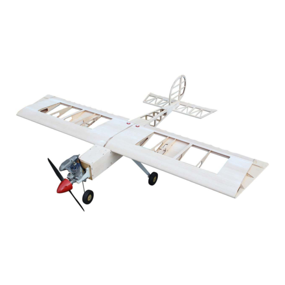
Code : SEA 255K
ASSEMBLY MANUAL
Speciications:
Wingspan--------------- 70.9 in--------------- 180 cm.
Wing area--------------- 1033.2 sq.in-------- 66.7 sq.dm.
Weight------------------- 7.7 lbs--------------- 3.5 kg.
Length------------------- 57.8 in--------------- 146.8 cm.
Engine------------------- 10cc - 15cc gasoline.
---------------------------- .60 -.91 glow engine.
---------------------------- 1200-1500 Watt Brushless Motor.
Radio--------------------- 4 channels with 5 servos.
Electric conversion: Optional.
1
Advertisement
Table of Contents

Related Manuals for Seagull Models MASTER SCALE KIT EDITION CLASSIC UGLY STICK 70.9


Summary of Contents for Seagull Models MASTER SCALE KIT EDITION CLASSIC UGLY STICK 70.9
- Page 1 Code : SEA 255K ASSEMBLY MANUAL Speciications: Wingspan--------------- 70.9 in--------------- 180 cm. Wing area--------------- 1033.2 sq.in-------- 66.7 sq.dm. Weight------------------- 7.7 lbs--------------- 3.5 kg. Length------------------- 57.8 in--------------- 146.8 cm. Engine------------------- 10cc - 15cc gasoline. ---------------------------- .60 -.91 glow engine. ---------------------------- 1200-1500 Watt Brushless Motor. Radio--------------------- 4 channels with 5 servos.
-
Page 2: Additional Items Required
Instruction Manual. Master Scale Kit Edition Classic Ugly Stick 70.9” INTRODUCTION. Master Scale Kit Edition Classic Ugly Stick 70.9” hank you for choosing the Build Master Scale Kit Edition Classic Ugly Stick 70.9” Up Kit by SG Models. he was de- signed with the beginner to intermediate sport lyer in mind. -
Page 3: Kit Contents
KIT CONTENTS. - Die cut Partern for all Kit. - Page 4 Instruction Manual. Master Scale Kit Edition Classic Ugly Stick 70.9”...
- Page 6 Instruction Manual. Master Scale Kit Edition Classic Ugly Stick 70.9”...
- Page 8 Instruction Manual. Master Scale Kit Edition Classic Ugly Stick 70.9” - Special part for Wing and Tail. - Balsa stick for stabilizer, Rudder and Fin. • 8 x 10 x 700mm balsa (4 per kit) • 8 x 12 x 160mm balsa (2 per kit) •...
-
Page 9: Tips For Getting Started
- Hardware Pack. • Includes hinges, horns, screws, fuel tank, landing gear wire, straps, wheels, wheel collars, spinner, glue, sanding block, aluminum wing tube, pushrod and nylon pushrod tubing. • 8mm dia. x 20mm Dowels for wing joiner . - Documentaion. •... - Page 10 Instruction Manual. Master Scale Kit Edition Classic Ugly Stick 70.9” WING PANEL CONSTRUCTION. - his section shows you how to construct one half of the wing. Repeat the instructions for the other half. 2 Layers W3 W3 Trailing edge...
- Page 11 - Locate plywood Main Wing Spars WG and ribs W1 ~W10. - Slide the ribs into their corresponding positions. - Rotate each wing rib so they are sitting upright, perpendicular to the building board. - Use C/A glue to secure airfoil W1~ W10. Secure leading edge - Use white glue for Main Wing Spars (WG ) as shown.
- Page 12 Instruction Manual. Master Scale Kit Edition Classic Ugly Stick 70.9” - Locate and use white glue to apply - Locate and use CA glue to assembly the balsa block stick to leading edge as wing tip. shown. - Locate and use CA glue to assembly the - Carefully block sand plywood string, airfoil ( AIL ) to wing tip as shown.
- Page 13 NOTE: Make sure each join is posi- - Use the white glue to secure wing tube. tioned correctly before you apply a drop of CA. CA dries very quickly when two pieces of wood come together. - Locate and use CA glue to secure the servo mount to the airfoils as shown.
- Page 14 Instruction Manual. Master Scale Kit Edition Classic Ugly Stick 70.9” - he wing sheet of trailing edge. - Locate the trailing edge sheeting. Use white glue to secure the trailing edge sheeting WSH8 (x2) at both sides. - Use the white glue at the edge of air-...
- Page 15 - Carefully saw of any overhang ma- terial, then block sand the root ends of the spars, leading edge, and trailing edge lush with the pre-angled wing rib. Use a large sanding block and sand slowly to keep the end of the wing panel straight and true.
- Page 16 Instruction Manual. Master Scale Kit Edition Classic Ugly Stick 70.9” - Finish for the right wing and let wing. - Slide the other wing panel onto the tube Finish for the right wing and let wing. and push the two halves together.
- Page 17 - Test it the hinges by inserting a a sin- gle easy hinge halfwway into each slot in the trailing edge of the wing. Place a pin through the hinge to prevent the hinge sliding into the wing. - Your wing panel should now look like picture above.
- Page 18 Instruction Manual. Master Scale Kit Edition Classic Ugly Stick 70.9” - Locate and assemble fuselage front S1 and fuselage rear S1B, join them by S3. Repeat for the other fuselage side using S2 front and S2B rear. Lay lat on plastic surface an apply CA glue.
- Page 19 - Locate and assemble landing gear - Locate and assemble wing mount MA3 mount M5 ( 3 layers) to fuselage side as ( 3 layers) to fuselage side as shown. shown. - Locate and assemble wing mount MA3 ( 3 layers) to fuselage side as shown. - Locate and assemble servo mount M2 and F5 to fuselage side as shown.
- Page 20 Instruction Manual. Master Scale Kit Edition Classic Ugly Stick 70.9” F3 F4 - Use C/A glue to secure formers F6~F9. - Use 30min epoxy to glue F2(2pcs), F3, F4, F5, M1, M2, M3(3pcs), M4(4pcs), M5(3pcs), F10, M7 in place. - Work quickly apply white glue to the tops of F6~F9 and 30min epoxy to F2(2pcs), F3, F4, F5, M1, M2, M3(3pcs), M4(4pcs), M5(3pcs), F10, M7.
- Page 21 - Before glue dries, check the fuselage is square down the center line. hen leave to set fully. Balsa square stock - Two pieces of Balsa Triangle stock are provided to reinforce the irewall-to-fu- selage joint. Cut notches in the Balsa Tri- angles where necessary to clear the blind nuts and pushrod holes, and then glue Right thrust...
- Page 22 Instruction Manual. Master Scale Kit Edition Classic Ugly Stick 70.9” - Two pieces of Nylon pushrod tubing are provided for making the outer sleeves of the elevator and rudder pushrod. - Work quickly apply C/A glue to the elevator and rudder pushrods at F6, F7, F8, F9, F10 as shown.
- Page 23 Reverse the fuselage to glue inside the sheet at the formers as shown - Work quickly apply white glue to the top of F6, F7, F8, F9, F10 and then in place the sheet top of fuselage as shown. Use C/A glue to secure the sheet top of fuselage Sheet bottom of fuselage...
- Page 24 Instruction Manual. Master Scale Kit Edition Classic Ugly Stick 70.9” - Carefully block sand at the bottom area of fuselage as shown - Work quickly apply white glue and use C/A glue to secure the sheet bottom of fuselage as done for sheeting at top of fuselage.
- Page 25 - Place in the magnet to a set per side as shown. - Use C/A glue to assembly the magnet to H3 as shown. - Locate the die-cut plywood hatch. In- spect both side and choose the best look- ing side for the top. Also locate the side braces/hatch retainers H2.
- Page 26 Instruction Manual. Master Scale Kit Edition Classic Ugly Stick 70.9” - Use C/A glue to secure the magnet. - Finish as shown. - Carefully block sand the all fuselage.
- Page 27 - Prepare for assembly the power engine. • Place in the fuel tank mount ( FM) and use C/A glue to secure as shown. • Apply for motor mount to 3 layers. FIT WINGS TO FUSELAGE. - Place in stabilizer mount ( M6) to fuse- lage and use C/A glue to secure.
- Page 28 Instruction Manual. Master Scale Kit Edition Classic Ugly Stick 70.9” - Locate the bolt to assemble the wing to the fuselage. RUDDER SET CONTRUCTION. - Locate use CA glue to assemble the bal- sa stick, special balsa part (FIN), as the paper plan kit for the rudder and in.
- Page 29 - Make angle 45 degree for each side of edge (about 12 – 15mm for Rudder con- trol throws). - Drill the holes dia 2mm for Rudder control horn and hole dia 3mm steel tail wheel gear. - Using sanding block as a guide, carve and sand the front of the leading edge to a round shape.
- Page 30 Instruction Manual. Master Scale Kit Edition Classic Ugly Stick 70.9” STABILIZER SET CONTRUCTION. Balsa sticks Bevel - Locate and use balsa sticks and special balsa part (STA) to assembly the stabiliz- er ( as in the paper plan) by CA glue.
- Page 31 - Use a hobby knife to cut slots in the trailing edge of the horizontal stabilizer and leading edge of the elevator. Elevator - Make sure the slots are cut on the center lines of the trailing edge of the horizontal stabilizer and the leading edge of the el- evator.
- Page 32 Instruction Manual. Master Scale Kit Edition Classic Ugly Stick 70.9” FIT ALL TO SETUP. COVERING THE CLASSIC UGLY STICK. NOTE: Always be careful when trimming excess covering material of the wood parts that you don’t “score” or cut into the wood. Scoring a critical structural component of the airplane could seriously weaken its strength and possibly cause an in-light failure.
- Page 33 1. COVER THE VERTICAL STABILIZER. Wrap up NOTE: When applying covering to an Using iron open structure, like this Fin and Rud- der, you should completely adhere the covering to all the outside edges of the structure irst. hen go back and shrink the middle of the covering tight.
- Page 34 Instruction Manual. Master Scale Kit Edition Classic Ugly Stick 70.9” 2. COVER THE HORIZONTAL STABILIZER - Covering the horizontal stabilizer is vir- tually the same as covering the vertical stabilizer. Wrap up Using iron Bottom face 3. COVER THE FUSELAGE.
- Page 35 Top face Using knife Top face Using iron...
-
Page 36: Cover The Wing
Instruction Manual. Master Scale Kit Edition Classic Ugly Stick 70.9” 4. COVER THE HATCH. 5. COVER THE WING. Wrap up Wrap up Using iron Using iron Using iron Cover for Aileron... - Page 37 Bottom wing panel Top wing panel...
-
Page 38: Final Assembly
Instruction Manual. Master Scale Kit Edition Classic Ugly Stick 70.9” FINAL ASSEMBLY. NOTE: To avoid scratching your new aero plane we suggest that you cover your work- bench with an old towel. Keep a couple of jars or bowls handy to hold the small parts af- ter you open the bags. -
Page 39: Hinging The Aileron
4) Delect the aileron and completely satu- HINGING THE AILERON. rate each hinge with thin C/A glue. he ailer- ons front surface should lightly contact the Note : he control surfaces, including the ai- wing during this procedure. Ideally, when lerons, elevators, and rudder, are prehinged the hinges are glued in place, a 1/64”... -
Page 40: Wing Assembly
Instruction Manual. Master Scale Kit Edition Classic Ugly Stick 70.9” 7) Repeat this process with the other wing WING ASSEMBLY. panel, securely hinging the aileron in place. Please see below pictures. 8) Ater both ailerons are securely hinged, irmly grasp the wing panel and aileron to make sure the hinges are securely glued and cannot be pulled out. -
Page 41: Installing The Aileron Servos
INSTALLING THE AILERON SERVOS. Electric wire. 3) Attach servo lead to the aileron servo. At- tach the string to the servo lead and carefully thread it though the wing. Once you have thread the lead throught the wing, remove the string so it can use for the other servo lead. - Page 42 Instruction Manual. Master Scale Kit Edition Classic Ugly Stick 70.9” 4) Tape the servo lead to the wing to prevent AILERON PUSHROD HORN it from falling back into the wing. INSTALLATION. Please see below pictures. Plastic tape. 5) Reinstall the servo into the servo mount...
-
Page 43: Installing The Fuselage Servos
Servo arm. Snap keeper. Nylon Snap keeper. Hex Nut. Wing bolt. Fuel tubing. ATTACHMENT WING- FUSELAGE. Please see below pictures. INSTALLING THE FUSELAGE SERVOS. Because the size of servos difer, you may need to adjust the size of the precut opening in the mount. - Page 44 Instruction Manual. Master Scale Kit Edition Classic Ugly Stick 70.9” THROTTLE SERVO ARM INSTALLATION. Install adjustable servo connector in the servo arm as same as picture below: Adjustable servo connector. Switch. Loctite secure. Servo arm. INSTALLING THE ENGINE SWITCH. hrottle servo arm.
-
Page 45: Fuel Tank Installation
5) With the stopper assembly in place, the weighted pick-up should rest away from the rear of the tank and move freely inside the tank. he top of the vent tube should rest just below the top of the tank. It should not touch the top of the tank. -
Page 46: Engine Mount Installation
Instruction Manual. Master Scale Kit Edition Classic Ugly Stick 70.9” Blow through one of the lines to ensure the fuel lines have not become kinked inside the fuel tank compartment. Air should low through easily. Ignition Module. ENGINE MOUNT INSTALLATION. - Page 47 6) Connect the Z-bend in the 450mm throttle pushrod to the outer hole of the carburetor arm. 7) Slide the throttle pushrod wire into the tube. Position the engine between the mounts. Use four M4x30mm machine screws to secure the engine to the mount as shown.
- Page 48 Instruction Manual. Master Scale Kit Edition Classic Ugly Stick 70.9” ELECTRIC POWER CONVERSION. 1) Locate the items neccessary to install the electric power conversion included with your model. 8) Reinstall the servo horn by sliding the connector over the pushrod wire. Center...
- Page 49 4mm. 3x15mm. 4mm. Blind nut. M4x60mm...
-
Page 50: Installing The Spinner
Instruction Manual. Master Scale Kit Edition Classic Ugly Stick 70.9” he propeller should not touch any Speed control. part of the spinner cone. If it does, use a sharp modeling knife and carefully trim away the spinner cone where the propel- ler comes in contact with it. - Page 51 Collar. M4x20mm. M4x20mm. Collar.
-
Page 52: Nose Gear Installation
Instruction Manual. Master Scale Kit Edition Classic Ugly Stick 70.9” NOSE GEAR INSTALLATION. Please see below pictures Steering arm. Collar. Metal clevis. Collar. -
Page 53: Hinging The Elevators
4) With the stabilizer held irmly in place, HINGING THE ELEVATORS. use a pen and draw lines onto the stabilizer where it and the fuselage sides meet. Glue the elevator hinges in place using the same techniques used to hinge the ai- lerons. -
Page 54: Vertical Stabilizer Installation
Instruction Manual. Master Scale Kit Edition Classic Ugly Stick 70.9” Knife. 7) When you are sure that everything is aligned correctly, mix up a generous amount VERTICAL STABILIZER of 30 Minute Epoxy. Apply a thin layer to INSTALLATION. the top of the stabilizer mounting area and... - Page 55 3) Remove the stabilizer. Using a modeling 5) When you are sure that everything is knife, remove the covering from below the aligned correctly, mix up a generous amount lines you drew. of 30 Minute Epoxy. Apply a thin layer to the mounting slot in the top of the fuselage and to the sides and bottom of the vertical sta- bilizer mounting area.
- Page 56 Instruction Manual. Master Scale Kit Edition Classic Ugly Stick 70.9” 3) Hold the rudder in place and mark it where the music wire will enter. When you are happy with the it, ill the hole with epoxy and use CA to glue in the rudder hinges.
- Page 57 ELEVATOR - RUDDER PUSHROD HORN INSTALLATION. 1) Locate items necessary to install eleva- tor and rudder pushrod. Rudder control horn. Elevator control horn. 2) Elevator and rudder pushrods assem- bly as pictures below. Cut. M2 clevis. M2 lock nut.
- Page 58 Instruction Manual. Master Scale Kit Edition Classic Ugly Stick 70.9” 2) Mount the wing to the fuselage. Using a couple of pieces of masking tape, place Rudder pushrod. M2 clevis. them on the bottom of the wing 100mm Hex nut.
-
Page 59: Control Throws
100 mm CONTROL THROWS. Ailerons: 12mm - 15mm up. 12mm - 15mm down. Elevator: 12mm - 15mm up. 12mm - 15mm down. Rudder: 20mm - 30mm let. 20mm - 30mm right. -
Page 60: Flight Preparation
Instruction Manual. Master Scale Kit Edition Classic Ugly Stick 70.9” FLIGHT PREPARATION. PREFLIGHT CHECK. Check the operation and direction 1) Completely charge your trans- of the elevator, rudder, ailerons and mitter and receiver batteries before throttle. your irst day of lying. - Page 61 If you have any queries, or are interested in our products, please feel free to contact us Factory : 12/101A - Hamlet 4 - Le Van Khuong Street - Dong hanh Ward - Hoc Mon District - Ho Chi Minh City - Viet Nam. Oice : 62/8 Ngo Tat To Street - Ward 19 - Binh hanh District - Ho Chi Minh City - Viet Nam Phone : 848 - 37114542 or 848- 36018777...
Need help?
Do you have a question about the MASTER SCALE KIT EDITION CLASSIC UGLY STICK 70.9 and is the answer not in the manual?
Questions and answers