Table of Contents
Advertisement
Quick Links
A S S E M B L Y M A N U A L
Code:
SEA209N
" Graphics and speciications may change without notice " .
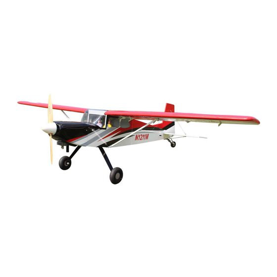
Speciications:
Wingspan---------------- 87.6 in ----------------- 222.2 cm.
Wing area--------------- 1072.6 sq.in ----------- 69.2 sq.dm.
Weigth------------------- 16.3 lbs----------------- 7.4 kg.
Length-------------------- 61.2 in------------------ 155.5 cm.
Recommended engine size 33cc.
Radio---------------------- 7 channels with 10 servos.
Flying skill level intermediate/ advanced.
1
Advertisement
Table of Contents

Related Manuals for Seagull Models Maxi Lift SEA209N


Summary of Contents for Seagull Models Maxi Lift SEA209N
- Page 1 A S S E M B L Y M A N U A L Code: SEA209N “ Graphics and speciications may change without notice “ . Speciications: Wingspan---------------- 87.6 in ----------------- 222.2 cm. Wing area--------------- 1072.6 sq.in ----------- 69.2 sq.dm. Weigth------------------- 16.3 lbs----------------- 7.4 kg.
-
Page 2: Kit Contents
Instruction Manual. Maxi Lift 87.6" wingspan, 33cc INTRODUCTION. hank you for choosing the MAXI LIFT ARF by SG MODELS . he MAXI LIFT was de- signed with the intermediate/advanced sport lyer in mind. It is a semi scale airplane which is easy to ly and quick to assemble. -
Page 3: Additional Items Required
KIT CONTENTS. HINGING THE FLAP. SEA209N Maxi Lift 87.6" wingspan, 33cc SEA20902 Wing Set SEA20903 Tail Set SEA20904 Fiberglass Cowling SEA20905 Canopy SEA20906 Landing Gear SEA20907 Wheels SEA20908 Wing struts SEA20909 Pilot ADDITIONAL ITEMS REQUIRED. M2x10mm. 0.75- 0.91 2-stroke. 0.91-1.25 4-stroke. -
Page 4: Hinging The Elevator
Maxi Lift 87.6" wingspan, 33cc Instruction Manual. NOTE : he hinge is constructed of a spe- HINGING THE ELEVATOR. cial material that allows the C/A to wick Note : he control surfaces, including the ai- or penetrate and distribute throughout lerons, elevators, and rudder, are prehinged the hinge, securely bonding it to the wood with hinges installed, but the hinges are not... -
Page 5: Hinging The Rudder
7) Repeat this process with the other wing panel, securely hinging the aileron in place. 8) Ater both ailerons are securely hinged, irmly grasp the wing panel and aileron to make sure the hinges are securely glued and cannot be pulled out. Do this by carefully ap- plying medium pressure, trying to separate Epoxy. -
Page 6: Installing The Main Landing Gear
Instruction Manual. Maxi Lift 87.6" wingspan, 33cc INSTALL RUDDER CONTROL HORN. Repeat steps to install the rudder control horn as same as steps done for ailerons. Epoxy. Aileron control horn. INSTALL ELEVATOR CONTROL HORN. Epoxy. Fiberglass control horn. Epoxy. Rudder control horn. INSTALLING THE MAIN Epoxy. - Page 7 Collar. Collar.
- Page 8 Instruction Manual. Maxi Lift 87.6" wingspan, 33cc...
-
Page 9: Installing The Fuselage Servos
INSTALLING THE FUSELAGE SERVOS. Because the size of servos difer, you may need to adjust the size of the precut opening in the mount. he notch in the sides of the mount allow the servo lead to pass through. Minimum servo spec. Torque : 115.3 oz-in (8.3 kg-cm) @ 4.8V;... -
Page 10: Installing The Switch
Instruction Manual. Maxi Lift 87.6" wingspan, 33cc INSTALLING THE SWITCH. Install the switch into the precut hole in the side, in the fuselage. 3/32” Hole. Elevator servo arm. Trim and cut. Rudder servo. Servo tow. Switch for engine. Servo capping. Trim and cut. -
Page 11: Mounting The Engine
5) Slide the pushrod tube in the irewall and guide it through the fuel tank mount. Use medium C/A to glue the tube to the irewall and the fuel tank mount. 6) Connect the Z-bend in the 600mm throt- tle pushrod to the outer hole of the carbure- tor arm. -
Page 12: Installing The Stopper Assembly
Instruction Manual. Maxi Lift 87.6" wingspan, 33cc THROTTLE SERVO ARM INSTALLATION. Install adjustable servo connector in the servo arm as same as picture below: Adjustable Servo Loctite secure. connector. Servo arm. 1 PCS INSTALLING THE STOPPER ASSEMBLY. 1) Using a modeling knife, carefully cut of the rear portion of one of the 3 nylon tubes leaving 1/2”... -
Page 13: Fuel Tank Installation
5) With the stopper assembly in place, the weighted pick-up should rest away from the rear of the tank and move freely inside the tank. he top of the vent tube should rest just below the top of the tank. It should not touch the top of the tank. - Page 14 Instruction Manual. Maxi Lift 87.6" wingspan, 33cc Vent tube. Fuel pick up tube. Fuel ill tube. 9) Connect the lines from the tank to the en- gine and muler. he vent line will connect to the muler and the line from the clunk to the carburetor.
- Page 15 ELECTRIC POWER CONVERSION. Locate the items neccessary to install the electric power conversion included with your model. 2) While keeping the back edge of the cowl lush with the marks, align the front of the cowl with the crankshat of the engine. he front of the cowl should be positioned so the crankshat is in nearly the middle of the cowl opening.
- Page 16 Instruction Manual. Maxi Lift 87.6" wingspan, 33cc Blind nut. M5x30mm and washers. Attach the motor to the front of the electric motor box using four 5mm blind nut, four M5x30mm hex head bolts to cure the motor. Please see picture shown. M5x25mm.
- Page 17 Speed control. Minimum servo spec. Torque : 115.3 oz-in (8.3 kg-cm) @ 4.8V; 157.8 oz-in (11.3 kg-cm) @ 6.0V 180.1 oz-in (12.9 kg) @ 7.4V...
- Page 18 Instruction Manual. Maxi Lift 87.6" wingspan, 33cc 5) Use dental loss to secure the connection so they cannot become unplugged. 1) Using a small weight (Weighted fuel pick- up works well) and string, feed the string 6) Secure the servo to the aileron hatch using through the wing as indicated.
- Page 19 AILERON PUSHROD NSTALLATION. 100mm. M3 clevis. M3 lock nut. Wing 9) Set the aileron hatch in place and use a INSTALLING THE FLAP SERVO. Phillips screw driver to install it with four wood screws. Repeat the procedure for the aileron servo.
- Page 20 Instruction Manual. Maxi Lift 87.6" wingspan, 33cc 90mm. M3 clevis. M3 lock nut. Wing INSTALLING TOW RELEASE FOR SAIL PLANE. It is best to operate the aero-tow release mechanism using a momentary switch Screw the aero-tow mechanism into the mounted on the joystick. he servo travel hole just behind the canopy, and apply must be set accordingly.
-
Page 21: Installing The Horizontal Stabilizer
INSTALLING THE HORIZONTAL STABILIZER. - Page 22 Instruction Manual. Maxi Lift 87.6" wingspan, 33cc 1) Using a ruler and a pen, locate the center- line of the horizontal stabilizer, at the trail- Remove the covering. ing edge, and place a mark. Use a triangle and extend this mark, from back to front, across the top of the stabilizer.
- Page 23 3) While holding the vertical stabilizer irm- ly in place, use a pen and draw a line on each side of the vertical stabilizer where it meets the top of the fuselage. Pen. INSTALLING VERTICAL FIN. 4) Remove the stabilizer. Using a modeling knife, remove the covering from below the lines you drew.
-
Page 24: Elevator Pushrod Installation
Instruction Manual. Maxi Lift 87.6" wingspan, 33cc 6) When you are sure that everything is aligned correctly, mix up a generous amount of Flash 30 Minute Epoxy. Apply a thin lay- er to the mounting slot and to bottom of the vertical stabilizer mounting area. - Page 25 M3 clevis. Crimp. Metal connector. Cable end. 810mm. 810mm. 185mm. THE TAIL WHEEL - STRUT SUPPORT. M2 clevis. M2 clevis. M2 lock nut. M2 lock nut. Locate items necessary to install tail wheel. Bend at the mark. Aluminum tail landing gear. 3x20mm...
- Page 26 Instruction Manual. Maxi Lift 87.6" wingspan, 33cc Bend at the mark. Metal clevis. Fuel tubing. Hex nut. INSTALLING TAIL STRUT SUPPORT. he tail strut system assembly follow pic- tures below. Fuel tubing. Hex nut. 810mm. 810mm. 280mm Metal clevis. M2 clevis. M2 clevis.
- Page 27 Epoxy. INSTALLATION PILOT AND CANOPY. 1) Locate items necessary to install pilot and canopy. Epoxy. 2) A scale pilot is included with this ARF. he Pilot included itting well to the cock- pit. (or you can order others scale pi- lot igures made by SG Models.
-
Page 28: Apply The Decals
Instruction Manual. Maxi Lift 87.6" wingspan, 33cc Attach the aluminium tube into fuselage. APPLY THE DECALS. 1) If all the decals are precut and ready to Wing tube. stick. Please be certain the model is clean and free from oily ingerprints and dust. Position decal on the model where desired, using the photos on the box and aid in their location. - Page 29 Wing bolt. M3x25mm. Wing. INSTALLATION WING- FUSELAGE STRUTS. M3x25mm. Fuselage. Wing. Wing.
-
Page 30: Control Throws
Instruction Manual. Maxi Lift 87.6" wingspan, 33cc With the wing attached to the fuse- lage, all parts of the model installed ( ready to ly), and empty fuel tanks, hold the model at the marked bal- ance point with the stabilizer level. Lit the model. -
Page 31: Flight Preparation
FLIGHT PREPARATION. PREFLIGHT CHECK. Check the operation and direction of the 1) Completely charge your transmitter and elevator, rudder, ailerons and throttle. receiver batteries before your irst day of lying. A) Plug in your radio system per the 2) Check every bolt and every glue joint in manufacturer’s instructions and turn eve- the MAXI LIFT to ensure that everything is rything on. - Page 32 Maxi Lift 87.6 in wingspan, 33cc Instruction Manual. If you have any queries, or are interested in our products, please feel free to contact us Factory : 12/101A - Hamlet 4 - Le Van Khuong Street - Dong hanh Ward - Hoc Mon District - Ho Chi Minh City - Viet Nam.
Need help?
Do you have a question about the Maxi Lift SEA209N and is the answer not in the manual?
Questions and answers