Table of Contents
Advertisement
Quick Links
Advertisement
Table of Contents

Related Manuals for T+A DD 1230 R


Summary of Contents for T+A DD 1230 R
- Page 1 OPERATING INSTRUCTIONS DD 1230 R DD 1530 R V 2.7 Bestell-Nummer 9103 – 0282...
- Page 2 Welcome. We are delighted that you have decided to purchase a product. With the addition of the digital surround decoder to your Hi-Fi system you are expanding it to embrace a completely new dimension: Audio-Vision. With the digital surround decoder you can play Dolby Surround, Dolby Digital and dts encoded television pro- grammes, video films and DVDs and experience a genuine “live”...
-
Page 3: Table Of Contents
Contents Operation Front panel controls ..............................4 Remote control ................................8 Menu control system ............................... 9 • Main menu ................................. 10 Connections, using the unit for the first time System configuration ............................12 • Device Setup..............................13 • Speaker Setup ..............................14 Loudspeaker position menu ......................... -
Page 4: Front Panel Controls
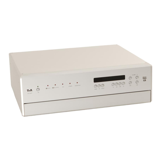
Front panel controls DD 1230 R DD 1530 R The decoder’s mains On / Off switch. • Switching to surround mode. If you are in stereo mode, pressing this button briefly • Switching on and off switches to surround mode, and for a period of about... - Page 5 – This button is designed for possible later function expan- The decoder features a digital volume control: every time sions. you press one of the volume buttons the volume in- creases or decreases by 1.5 dB. If you hold one of the volume buttons pressed in for longer than a second, the volume continues to rise or fall until you release the button again.
- Page 6 Decoder mode display Integral screen The display elements of the digital surround decoder are DIGITAL grouped together in a clearly laid out screen: The decoder automatically selects this mode if it detects at the input a digital multi-channel signal which is en- coded using Dolby Digital.
- Page 7 VCR-recordings using the digital sur- round decoder button on the decoder is used to select a recording source independently of the current source device which you are viewing or listening to. This facility allows you to record an AV source device (e.g.
-
Page 8: Remote Control
Remote control of the Surround Decoder General information F1 only: switch the handset to Hi-Fi mode. The digital surround decoder can be controlled using the Direct source select button F11 remote control handset, or the F1 system remote control unit. If you are using the F1 handset, it must first Note: be switched to Hi-Fi mode. -
Page 9: Menu Control System
Menu control system To keep the control panel of the digital surround decoder The following table shows how the menu control system as compact and uncluttered as possible, the panel does is operated using the remote control buttons, or the but- not include dedicated buttons for controlling the decoder tons on the decoder’s front panel. -
Page 10: Main Menu
Main Menu The 'Main Menu' is designed for adjustments to the To open the 'Main Menu' press the remote control button decoder which are only occasionally required for daily briefly, or the button on the listening; perhaps to allow for temporary changes in the decoder’s front panel. - Page 11 ProLogic II mode: Subwoofer level: This menu point enables you to set the Dolby ProLogic II If you switch on the subwoofer in the 'Speaker Setup', in decoder to suit varying programme material. this menu point you can adjust its level within the range - 10 (dB) to +10 (dB) in order to match its volume to the Movie acoustic conditions in your listening room, and to match...
-
Page 12: System Configuration
System Configuration In the 'Device Setup' you can adjust the settings for all This procedure only needs to be carried out when you are installing the system, or when you are adding or the audio and video components of your surround sys- replacing individual components of the system. -
Page 13: Device Setup
Device Setup You can call up the 'Device Setup' by pressing the re- button on the front panel of the decoder; in either case hold the button pressed in for about two seconds. mote control button , or the Screen brightness: On-screen language: The on-screen menus can be displayed on the TV The brightness of the screen can be set to suit your... -
Page 14: Speaker Setup
Speaker Setup The first purpose of the 'Speaker Setup' is to allow you The last three menu points enable you to adjust the loudspeakers to suit the acoustic and spatial character- to distribute the output signals correctly to the loud- istics of your listening room. - Page 15 Rear Size: Subwoofer: Defines the size and bass capacity of the rear surround In this menu point you set whether a subwoofer is pres- loudspeakers. Select one of the following settings: *) ent in your loudspeaker system. Select one of the fol- lowing settings: none if no surround loudspeakers are present.
-
Page 16: Loudspeaker Position Menu
Speaker Position Setup In the 'Speaker Position Setup' you can enter the dis- This enables the decoder to compensate for timing dis- crepancies due to differences in speaker location. tance from the listening position (in 0.3 m increments) for each loudspeaker separately. As the illustration shows, you use the select buttons to move to the input positions in the following sequence. -
Page 17: Loudspeaker Balance Menu
Speaker Balance Setup To ensure that the decoder supplies a balanced sound The purpose of the 'Speaker Balance Setup' is to adjust image, the system allows you to adjust the volume of the the level of all the channels. individual channels to provide a harmoniously balanced arrangement. -
Page 18: Tone Control Menu
Tone Control Menu The decoder features an active tone control system The treble / bass balance can be adjusted separately for (+/- 6 dB) whose purpose is to compensate for the un- all the output channels, and can therefore compensate wanted influence on playback quality of your listening for problems caused by the location of individual speak- room, or of imperfect loudspeaker positions. -
Page 19: Video Setup
Video Setup Optimum picture quality is only possible if the picture There is a large number of different picture norms on the norms of all the video components in the system are set market, but not all of them are supported by all AV up to match each other, and if the correct cables source devices and TV sets. -
Page 20: Source Setup (Av Source Devices)
Source Setup AV source devices The purpose of the 'Source Setup' is to integrate the AV Combination source devices (e.g. DVD players and set-top boxes) provide both an analogue stereo signal source devices connected to the decoder into a and a digital surround signal. system. -
Page 21: Source Setup
Source Setup In the first column of the 'Source Setups Menu' you In the fourth column you assign a source button on the assign a name to every AV source device which is con- remote control handset to the AV source device; you can nected to the decoder. - Page 22 Video column) column) The source devices connected to the decoder can be In this column you enter the decoder’s video input to selected by repeatedly pressing the button on which each AV source device is connected. The follow- ing Video decoder inputs are available: the front panel, or the button on the remote con- trol handset.
-
Page 23: Example: Integrating A Dvd 1210 R
Source Setup (Example: Integrating a DVD 1210 R) Notes on wiring and assigning sources: Source selection • Connect the analogue stereo output of the DVD player directly to the pre-amplifier input AUX 1. If you repeatedly press the button on the remote control handset (or the button on •... -
Page 24: Back Panel Connections
Connections DD 1230 R DD 1530 R DIGITAL INPUT 5.1 OUTPUT (CINCH) The three inputs for digital source devices with co-ax Output for external loudspeakers or external power am- digital outputs can be assigned to any picture input, or plifiers. - Page 25 The stoppers are simply a push-fit in the terminals, and can be prised out from the rear using a suitable tool such as a knife blade. Note (only DD 1230 R): If your AV device does not include a SCART socket, use AUX AV...
- Page 26 Connector pin assignment for SCART sockets View from outside DVD and SET-TOP BOX RGB / Video S-Video RGB / Video S-Video RGB / Video S-Video Audio Out (R) Audio Out (R) Audio Out (R) Audio Out (R) Audio In (R) Audio In (R) Audio In (R) Audio In (R)
-
Page 27: Safety Notes
Safety notes All the components we use meet the currently valid Ger- This device should never be used without proper super- man and European safety norms and standards. vision. The decoder should be set up well out of the reach of small children. This applies to all electrical Our production areas are supervised by highly qualified equipment. -
Page 28: Fcc Information To The User
Approved usage Device approval and conformity with EC directives This device is designed exclusively for reproducing In its original condition the unit meets all currently valid sound and/or pictures in the domestic environment. It is German and European regulations. It is approved for use to be used in a dry indoor room which meets all the rec- as stipulated within the EC. -
Page 29: Installation, Using The Decoder For The First Time
Installation, using the unit for the first time General notes on setting up the unit: Before you start: Carefully unpack the digital surround decoder and store Before you connect your digital surround decoder to your the original packing materials carefully. The carton and Hi-Fi system please check the sockets and the packing are specially designed for this unit and will be software version of your pre-amplifier, integrated ampli-... - Page 30 Notes on connections: • Be sure to push all plugs firmly into their sockets. Loose connections can cause hum and other un- wanted noises. • Deploy all mains leads, loudspeaker cables and remote control leads as far as possible from low-level leads (inter-connects) and aerial cables.
- Page 31 Connecting the TV set and the surround loudspeakers to the decoder: Connect the components as shown in wiring diagram 1. If you have a TV 720, TV 820 or TV 920 television, This is the procedure: please set it up as follows: •...
-
Page 32: Wiring Diagrams
'Trouble- shooting' section in these operating instructions. Use of banana plugs: see the section entitled 'Back panel connections'. Wiring diagram 1 Connecting the digital surround decoder to a TV set and the surround loudspeakers DD 1230 R. -
Page 33: Connecting The Tv Set And Surround Speakers To The Decoder
Connecting the digital surround decoder to a TV set and the surround loudspeakers DD 1530 R. -
Page 34: Link
LINK • Finally connect the mains power supply and switch socket on the integrated amplifier. LINK the system on. Wiring diagram 2 Connecting the DD 1230 R to a integrated amplifier with TASI and R sockets. LINK... -
Page 35: Connecting A Dvd Player (Digital Picture Source)
Connecting the DD 1530 R to a integrated amplifier with TASI and R sockets. LINK... -
Page 36: Connecting A Cd Mechanism (Digital Sound Source)
CD player, connect its analogue output to the pre-amplifier input CD or AUX 1, and assign the source in the 'Source Setup'. Wiring diagram 3 A DVD player connected to the DD 1230 R. A DVD player connected to the DD 1530 R. -
Page 37: Connecting A Set-Top Box (Digital Sound And Picture Source)
CDs, or to exploit the artificial sound fields available in the decoder. CDs encoded with Dolby Sur- round and dts are available commercially. Wiring diagram 4 A CD mechanism connected to the DD 1230 R. A CD mechanism connected to the DD 1530 R. -
Page 38: Connecting A Sat Receiver (Analogue Sound And Picture Source)
Finally connect the mains power supply and switch the system on. Wiring diagram 5 A set-top box (digital sound and picture source) connected to the DD 1230 R. A set-top box (digital sound and picture source) connected to the DD 1530 R. -
Page 39: Sat Receiver (Analogue Sound And Picture Source) At The Aux-Av Input
If your set-top box does not feature a SCART socket, use a SCART adaptor lead. Please ask your special- dealer for advice. Wiring diagram 6 Analogue SAT receiver connected to the DD 1230 R. Analogue SAT receiver connected to the DD 1530 R. - Page 40 VIDEO AUX-AV input socket on the decoder. Wiring diagram 7 An analogue sound and picture source connected to the AUX-AV input of the DD 1230 R. An analogue sound and picture source connected to the AUX-AV input of the DD 1530 R.
-
Page 41: Video Recorder (Analogue Device With Record / Playback Facilities)
AUDIO (Cinch) sockets on the decoder and the video recorder. Wiring diagram 8 An analogue device with recording and playback facilities (video recorder) connected to the DD 1230 R. An analogue device with recording and playback facilities (video recorder) connected to the DD 1530 R. -
Page 42: Variations On Standard Wiring
Variations on standard wiring Special compatibility sets are available, to enable you to 4. The decoder in a home cinema set-up combine the decoder with amplifiers and receivers from The decoder can also be used for pure home cinema earlier generations of equipment, or with amplifiers / applications without the addition of a stereo pre- receivers of other makes, and also to use the unit in a... - Page 43 Optimising your system Loudspeaker cables, inter-connects Mechanical de-coupling Loudspeaker cables and signal leads (inter-connects) The base and surface on which your high-quality Hi-Fi have a significant influence on the overall reproduction equipment is set up have an important influence on the quality of your sound system, and their importance sound quality which the system can achieve.
-
Page 44: Trouble-Shooting
Trouble-shooting Many problems have a simple cause and a correspond- Problem: Machine does not switch on (green LED ingly simple solution. The following section describes a does not light up). few difficulties you may encounter, and the measures you need to take to cure them. Mains lead not plugged in correctly. - Page 45 Problem: No sound, or distorted sound. Problem: 'Main Menu' not displayed on the televi- sion screen. Incorrect audio connection to amplifier or Cause: TV set. Cause: Screen display of 'Main Menu' switched off in ‘Device Setup’. Remedy: Check connections against wiring diagram; push all connectors in firmly.
- Page 46 Problem: Monochrome picture only. Problem: Picture correct, but no sound audible through the decoder. Incompatible picture norms set on the TV, Cause: the decoder and the source device. Cause 1: No sound connection between source de- vice and decoder. Remedy: Set TV, decoder and source device to the same picture norm.
-
Page 47: Surround Systems - Explanatory Notes
Surround sound - explanatory notes General information: The following section is not concerned directly with the Dolby Pro Logic II Surround operation of your digital surround decoder, but is rather intended to explain some of the terms which arise in In this process serveral independent signal channels connection with surround systems. - Page 48 Sound field simulation Dolby Digital The surround processes already described require pro- Dolby Digital is a digital multi-channel surround system gramme material which is encoded using the appropriate which was developed specifically for spatial sound re- system, but the digital surround decoder also offers a production in connection with 35 mm cinema films.
-
Page 49: The Surround System
surround system Multi-channel reproduction based on surround technol- When the system is used in Pro Logic II mode, the TASI ogy does indeed open up new worlds of experience, but interface also ensures that the decoder is looped in at the technical implementation of a multi-channel surround the ideal point and at the optimum level in terms of signal system does involve a number of potential pitfalls. -
Page 50: Glossary
Glossary AV source device STANDBY A source device which supplies sound and picture sig- The digital surround decoder can be switched on from nals. The sound signals may be generated in analogue stand-by mode at any time by pressing a button on the or digital form. -
Page 51: Specification
Specification DD 1230 R DD 1530 R Decoder Analogue inputs: 500mV / 20 kΩ Digital inputs 5 x SP/DIF, 44.1 kHz, 48 kHz and 96 kHz (3 x co-axial, 2 x optical): A/D converter: 2 channel, 24 bit, 48 kHz... - Page 52 elektroakustik GmbH & Co. KG Herford Germany...
Need help?
Do you have a question about the DD 1230 R and is the answer not in the manual?
Questions and answers