
Subscribe to Our Youtube Channel
Related Manuals for T+A PH HV MM


Summary of Contents for T+A PH HV MM
- Page 1 Betriebsanleitung User manual Phonomodul / Phono Module PH HV PH HV Bestell Nr. / Order no. 9103 – 0481 DE / UK...
- Page 3 Seite / Page Deutsch ............4 English ............13...
- Page 4 Willkommen. Wir freuen uns, dass Sie sich für ein -Produkt entschieden haben. Mit dem High-End Phono-Vorverstärkermodul PH-HV oder PH-HV für den P/PA 3000 HV haben Sie eine hochwertige HiFi-Komponente der Spitzenklasse erworben, bei dessen Konzeption und Entwicklung den Wünschen des anspruchsvollen Musikliebhabers oberste Priorität eingeräumt wurde.
-
Page 5: Table Of Contents
Inhaltsverzeichnis Installation und Einstellung Vorwort ........................6 Allgemeine Einstellung .................... 7 Betrieb Einstellmöglichkeiten am Phono-Modul MM Einstellen der Eingangsempfindlichkeit ..............8 Einstellen der Eingangskapazität ................9 Einstellmöglichkeiten am Phono-Modul MC Einstellen der Eingangsempfindlichkeit ..............10 Einstellen der Eingangsimpedanz ................11 Sonstiges Betriebsstörungen .................... -
Page 6: Vorwort
Vorwort Einbau / Ausbau Der Ein- bzw. Ausbau des Phonomoduls in den P/PA 3000 HV darf nur durch oder eine autorisierte Fachwerkstatt erfolgen. Die Installation ist in der Service-Note S0128_PH_HV_Installation im Detail beschrieben. Einstellungen Um die höchstmögliche Wiedergabequalität zu erzielen müssen Tonabnehmersystem und Phono-Vorverstärker optimal aufeinander angepasst werden. -
Page 7: Allgemeine Einstellung
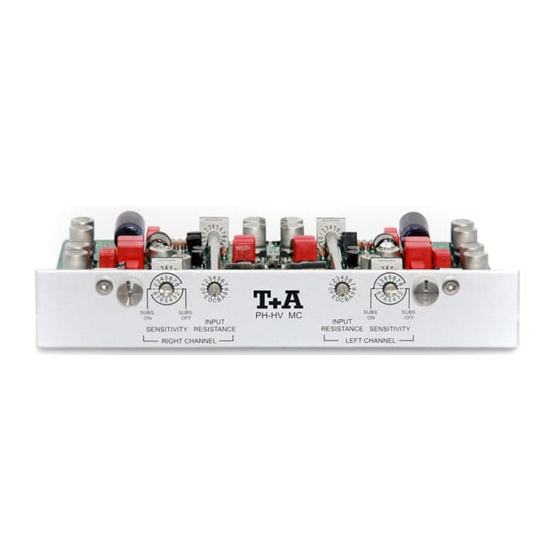
Allgemeine Einstellungen Anpassung entscheidender Bedeutung für Klangqualität eines Tonabnehmersystems ist die genaue Anpassung an den Verstärker. Deshalb ist das Phonomodul so konzipiert, dass es durch Drehschalter perfekt an alle gängigen Tonabnehmersysteme angepasst werden kann. Mit Hilfe eines kleinen Schraubendrehers können die einzelnen Schalterstufen eingestellt werden. -
Page 8: Einstellen Der Eingangsempfindlichkeit
Einstellen der Eingangsempfindlichkeit am Phono-Modul MM Einstellen der Mit den äußeren Drehschaltern (Sensitivity) wird die gewünschte Eingangs- Eingangsempfindlichkeit für den linken und rechten Kanal gemäß Tabelle empfindlichkeit 1 eingestellt. Die Eingangsempfindlichkeit kann in acht Stufen angepasst werden, jeweils mit oder ohne Subsonic Filter. (Sensitivity) Die benötigten Daten entnehmen Sie bitte den Herstellerangaben des Tonabnehmersystems. -
Page 9: Einstellen Der Eingangskapazität
Einstellen der Eingangskapazität am Phono-Modul MM Einstellen der Die Einstellung erfolgt gemäß Tabelle 2 durch Drehschalter für den linken Eingangs- und rechten Kanal. kapazität Die benötigten Daten entnehmen Sie den Herstellerangaben des Tonabnehmersystems. Wählen Sie den Wert, der den Herstellerangaben (Input Capacity) am nächsten liegt. -
Page 10: Einstellen Der Eingangsempfindlichkeit
Einstellen der Eingangsempfindlichkeit am Phono-Modul MC Einstellen der Mit den äußeren Drehschaltern (Sensitivity) wird die gewünschte Eingangs- Eingangsempfindlichkeit für den linken und rechten Kanal gemäß Tabelle empfindlichkeit 3 eingestellt. Die Eingangsempfindlichkeit kann in acht Stufen angepasst werden, jeweils mit oder ohne Subsonic Filter. (Sensitivity) Die benötigten Daten entnehmen Sie bitte den Herstellerangaben des Tonabnehmersystems. -
Page 11: Einstellen Der Eingangsimpedanz
Einstellen der Eingangsimpedanz am Phono-Modul MC Einstellen der Die Einstellung erfolgt gemäß Tabelle 4 durch Drehschalter für den linken Eingangs- und rechten Kanal. impedanz Die benötigten Daten entnehmen Sie den Herstellerangaben des Tonabnehmersystems. Wählen Sie den Wert, der den Herstellerangaben (Input Resistance) am nächsten liegt. -
Page 12: Betriebsstörungen
Betriebsstörungen Viele Betriebsstörungen haben eine einfache Ursache, die sich leicht beheben lässt. Im folgenden Abschnitt sind einige mögliche Störungen sowie Maßnahmen zu deren Behebung aufgeführt. Sollte sich eine aufgetretene Störung durch diese Hinweise nicht beheben lassen, so wenden Sie sich bitte und an eine -Fachwerkstatt. Die Wiedergabe ist im Ursache: Vergleich zu anderen... - Page 13 English...
- Page 14 Welcome We are delighted that you have decided to purchase a product. With the phono-module PH- or PH-HV for your P/PA 3000 HV you have acquired a top-quality piece of equipment which has been designed and developed with the wishes of discerning listeners as absolute top priority.
- Page 15 Contents Installation and Adjustment Preamble ........................ 16 General settings ...................... 17 Operation Adjustment facilities on the Phono module MM Adjust the input sensitivity ..................18 Adjust the input capacity ..................19 Adjustment facilities on the Phono module MC Adjust the input sensitivity ..................20 Adjust the input resistance ..................
-
Page 16: Preamble
Preamble Caution: Installation and de-installation of the Phono Preamplifier module must be carried out by or one of our authorized dealers. The installation procedure is described in detail in service note S0128_PH_HV_Installation . Adjustments To achieve the highest possible audio quality the Phono Preamplifier must be carefully adjusted to match the requirements of your cartridge. -
Page 17: General Settings
General Settings Adjustments Accurate matching is crucially important to the sound quality produced by a pick-up system. For this reason the phono module features a set of rotary switches which enable the user to adjust it perfectly to suit all current pick-up systems. -
Page 18: Adjustment Facilities On The Phono Module Mm Adjust The Input Sensitivity
Adjustment sensitivity on the Phono module MM Adjust the input The outer rotary switches are used to set the desired input sensitivity for sensitivity the left and right channels as shown in Table 1. The input sensitivity can be adjusted in 8 steps with and 8 steps without subsonic filter. The (Sensitivity) information about the requirements of your cartridge will be included in the manufacturer’s specification for the pick-up system you intend to use. -
Page 19: Adjust The Input Capacity
Adjustment capacity on the Phono module MM Adjust the input The inner rotary switches are used to set the desired input capacitance capacity for the left and right channels as shown in Table 2. The information about the requirements of your cartridge will be included in the manufacturer’s (Input Capacity) specification for the pick-up system you intend to use. -
Page 20: Adjustment Facilities On The Phono Module Mc Adjust The Input Sensitivity
Adjustment sensitivity on the Phono module MC Adjust the input The outer rotary switches are used to set the desired input sensitivity for sensitivity the left and right channels as shown in Table 3. The input sensitivity can be adjusted in 8 steps with and 8 steps without subsonic filter. The (Sensitivity) information about the requirements of your cartridge will be included in the manufacturer’s specification for the pick-up system you intend to use. -
Page 21: Adjust The Input Resistance
Adjustment resistance on the Phono module MC Adjust the input The inner rotary switches are used to set the desired input resistance for resistance the left and right channels as shown in Table 4. The information about the requirements of your cartridge will be included in the manufacturer’s (Input Resistance) specification for the pick-up system you intend to use. -
Page 22: Troubleshooting
Troubleshooting Many problems have a simple cause and a correspondingly simple solution. The following section describes a few difficulties you may encounter, and the measures you need to take to cure them. If you find it impossible to solve a problem with the help of these notes please disconnect the unit from the mains and ask your authorized ... -
Page 23: Fcc Information To The User
Approval and In its original condition the unit meets all currently valid European conformity regulations. It is approved for use as stipulated within the EC. By attaching the CE symbol to the unit declares its conformity with with EC directives the EC directives 2006/95/EC, 2004/108/EC and 2009/125/EC and the national laws based on those directives. -
Page 24: Einbaulage Des Phonomodul
Anhang / Appendix Einbaulage Phonomodul / Mounting position Phono module Um nachträglich Einstellungen am Phonomodul vorzunehmen, ist es erforderlich den Gehäusedeckel des P/PA 3000 HV zu entfernen. Abb. 3 zeigt die Position des gesteckten Moduls. Bitte beachten Sie hierzu folgende Punkte. -
Page 26: Anschluss-Schema
Anschluss-Schema / Wiring diagram... -
Page 27: Technische Daten
Technische Daten / Specification 100 μV ...1200 μV Eingangsempfindlichkeit (für Ausgangspegel 800 mVeff): 1 mV ... 10 mV Input sensitivity (for 800 mVeff output level): (MC)* (MM)* 55 Ω ... 1000 Ω* Eingangsimpedanz (MC): Input impedance (MC): Eingangskapazität (MM): 70 pF ... 460 pF* Input capacitance (MM): Frequenzgang (nach RIAA): + / - 0,05 dB... - Page 28 elektroakustik GmbH & Co. KG Herford Deutschland Germany Allemagne...
Need help?
Do you have a question about the PH HV MM and is the answer not in the manual?
Questions and answers