Campbell CR300 Series Operator's Manual
Hide thumbs
Also See for CR300 Series:
- Product manual (321 pages) ,
- Getting started manual (27 pages) ,
- Application note (19 pages)

Related Manuals for Campbell CR300 Series


Summary of Contents for Campbell CR300 Series
- Page 1 CR300-Series Datalogger Revision: 9/16 C o p y r i g h t © 2 0 1 6 C a m p b e l l S c i e n t i f i c , I n c .
- Page 3 Limited Warranty The CR300 Datalogger is warranted for three (3) years subject to this limited warranty: “Products manufactured by CSI are warranted by CSI to be free from defects in materials and workmanship under normal use and service for twelve months from the date of shipment unless otherwise specified in the corresponding product manual.
- Page 4 (435) 227-9106. Campbell Scientific is unable to process any returns until we receive this form. If the form is not received within three days of product receipt or is incomplete, the product will be returned to the customer at the customer’s expense.
- Page 5 Periodically (at least yearly) check electrical ground connections. • WHILE EVERY ATTEMPT IS MADE TO EMBODY THE HIGHEST DEGREE OF SAFETY IN ALL CAMPBELL SCIENTIFIC PRODUCTS, THE CUSTOMER ASSUMES ALL RISK FROM ANY INJURY RESULTING FROM IMPROPER INSTALLATION, USE, OR MAINTENANCE OF TRIPODS, TOWERS, OR ATTACHMENTS TO TRIPODS AND TOWERS SUCH AS SENSORS, CROSSARMS, ENCLOSURES, ANTENNAS, ETC.
-
Page 7: Table Of Contents
Table of Contents PDF viewers: These page numbers refer to the printed version of this document. Use the PDF reader bookmarks tab for links to specific sections. 1. Introduction ..............1 2. Precautions ..............1 3. Initial Inspection ............2 4. - Page 8 Table of Contents 6.1.2.2 Ratiometric Accuracy ............30 6.1.3 Current Measurements – Details ..........30 6.1.3.1 Voltage Ranges for Current Measurements ..... 31 6.1.3.2 0-20 mA and 4-20 mA Measurements ......31 Pulse Measurements – Details ............33 Period Averaging – Details ............... 34 Digital Input/Ouput –...
- Page 9 Table of Contents Internal Lithium Battery ..............52 9. Troubleshooting ............52 Station Status Summary ..............52 Basic Troubleshooting Procedure ............53 NAN and INF ..................54 Out of Memory Error ................. 55 Resetting the CR300 ................55 10. Glossary ..............56 Appendices A.
- Page 10 Table of Contents 7-1. Analog Voltage Measurement Range and Resolution ....... 43 7-2. Analog Voltage Measurement Accuracy Offsets ......44 7-3. Analog Voltage Measurement Speed ..........44 7-4. Analog Voltage Measurement Input Resistance and Current .... 44 7-5. Low-Level AC Ranges ..............46 7-6.
-
Page 11: Introduction
They can concentrate data, making it available over varied networks, and deliver it using your preferred protocol. The CR300 series also performs automated on-site or remote decision making for control and mobile- to-mobile communications. -
Page 12: Initial Inspection
On cabled items, the number is often found at the end of the cable that connects to the measurement device. The Campbell Scientific number may differ from the part or model number printed on the sensor by the sensor vendor. -
Page 13: Configure Software
CR300-Series Datalogger Configure Software Watch the video for Sections 4.1 – 4.2: CR300 QuickStart Part 2. NOTE To set up communications with a CR300-RF407-series datalogger, refer to the Datalogger RF407-Series Spread Spectrum Radio Option Communication Setup Guide. When LoggerNet, PC400, or PC200W is first run, the EZSetup Wizard runs automatically in a new window. - Page 14 CR300-Series Datalogger After the driver has been installed, connect the CR300 USB port to the PC with the included USB cable (pn 27555). The connection supplies 5 V power over USB as well as a communication link. NOTE The Power LED indicates the program and power state of the CR300. Because the CR300 ships with a program set to run on power-up, the Power LED will quickly flash 3 times every 10 seconds when powered over USB.
- Page 15 CR300-Series Datalogger The CR300 does not use a security code or a PakBus encryption key by default, so the Security Code can be set to 0 and the PakBus Encryption Key can be left blank. If either setting has been changed, enter the new code or key.
- Page 16 CR300-Series Datalogger The CR300 ships with a default program called QuickStart.CR300. If your CR300 is running another program, the program name will show in the Current Program field. If the current program is not QuickStart.CR300, visit www.campbellsci.com/start/cr300, where the program can be downloaded.
-
Page 17: Connect To The Cr300
CR300-Series Datalogger We are not going to do scheduled collections in this tutorial. Click Schedule Help to learn more about this option or refer to the Collect Data Tutorial. Click Next. Click Finish to complete the EZSetup Wizard and go to the Setup Screen. -
Page 18: Connect With Loggernet
CR300-Series Datalogger Click the Monitor Data tab. When the Monitor Data tab is first opened for a datalogger, values from the Public table are displayed. To view data from other tables, click Add. Add entire tables or select fields by dragging them into cells in the Monitor Data window. -
Page 19: Create A Program
CR300-Series Datalogger In the Table Monitor, select a data table in the Table Monitor list. The table is now displayed. Each table will update as described in Section 5.6, Monitoring Data (p. 23) View the Public table by selecting the Public table in the Table Monitor list. Click Disconnect to end the session. - Page 20 AC voltage. Select 50 Hz Noise Rejection for most of Europe and areas that operate at 50 Hz. A second prompt lists sensor support options. Campbell Scientific, Inc. (US) is probably the best fit if you are outside Europe. To change the first notch frequency or sensor support option for future programs, use the Program menu.
- Page 21 CR300-Series Datalogger For most sensors and measurements, a dialog window is then presented with several fields and options. Click Help to learn more about any field or option. Click OK in the dialog window to accept default options that include selection of 1 sensor named Temp_C, and PTemp_C as the reference temperature measurement.
- Page 22 CR300-Series Datalogger Wire sensors with power disconnected. To open a terminal on the CR300, use the included flat- blade screwdriver. Insert the wire, taking care to clamp the terminal on the conductor itself, not the insulation. Disconnect the USB cable. Attach the thermocouple to the CR300 as shown in Wiring Diagram. Click Next.
- Page 23 CR300-Series Datalogger Add measurements to the table by selecting them under Selected Sensors and then clicking on an output processing option in the center column of buttons. Select BattV under Selected Sensors and then click Average. Repeat this procedure for PTemp_C and Temp_C. Click Finish to compile the program.
-
Page 24: Wire Sensors And Devices
CR300-Series Datalogger Wire Sensors and Devices If the program was created in Short Cut, follow the wiring diagram created by Short Cut to attach sensors and devices to the datalogger. The wiring must match the diagram exactly for the sensors to be measured correctly. If the program was created directly in the CRBasic Editor, attach sensors and devices according to the options chosen for the measurement instructions and according to their individual product manuals. -
Page 25: Collect Data
CR300-Series Datalogger Sending a program this way erases all data tables saved on the CR300. Ensure that all critical data have been collected. If not, click No, and collect data before attempting to send the new program. Click Yes to confirm that data deletion is OK and to send the program to the CR300. After the program has successfully been sent to and compiled by the CR300, a Compile Results window... - Page 26 CR300-Series Datalogger Select the Collect Data tab. Select an option in What to Collect. • New data from datalogger (Append to data files) – collects only the data stored since the last data collection and appends this data to the end of the existing file.
-
Page 27: Collect Data With Loggernet
CR300-Series Datalogger 4.6.2 Collect Data with LoggerNet Open LoggerNet Connect. From the LoggerNet toolbar, click Main | Connect. In the Stations list, select the newly added CR300. Press Collect Now. Collect data from the OneMin table by clicking Collect Now. After LoggerNet collects the data, a window titled Data Collection Results opens. -
Page 28: View Data
FIGURE shows a typical installation using a Campbell Scientific enclosure. The CR300 has mounting holes through which small screws are inserted into nylon anchors in the backplate. -
Page 29: Apply Power
CR300-Series Datalogger Insert the three included nylon anchors into the backplate. Position them to align with the three mounting holes on the base of the CR300. Holding the CR300 to the backplate, screw the three included screws into the nylon anchors. FIGURE 4-2. -
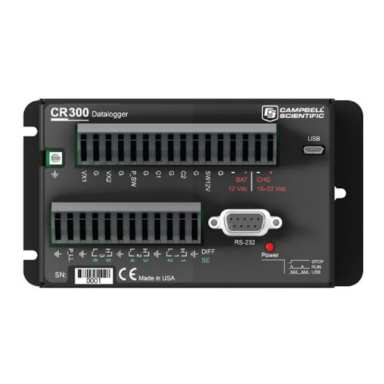
Page 30: Overview
CR300-Series Datalogger Overview Wiring Panel Overview Earth Ground FIGURE 5-1. CR300 Wiring Panel TABLE 5-1. CR300 Wiring Panel Terminal Definitions Analog Input Function C2 P_SW P_LL VX1 SE6 RS-232 SW12 Single Ended Differential 4 to 20 or 0 to 20 mA ... -
Page 31: Configuring The Cr300
CR300-Series Datalogger Configuring the CR300 Settings on the CR300 default to those necessary to communicate with a PC via USB and to accept and execute user application programs. For more complex applications, some settings may need adjustment. Settings can be changed through Device Configuration Utility or through datalogger support software. -
Page 32: Configuring Datalogger Support Software
CR300. The CR300 can store a number of programs in memory, but only one program is active at a given time. Two Campbell Scientific software applications, Short Cut and CRBasic Editor, can be used to create CR300 programs. -
Page 33: Monitoring Data
CR300-Series Datalogger LoggerNet Connect | Send New • LoggerNet Connect | File Control | Send • • LoggerNet Setup CRBasic Editor | Compile, Save and Send • Device Configuration Utility | Logger Control | Send Program • Device Configuration Utility | File Control | Send •... -
Page 34: Typical Data Table
CR300-Series Datalogger data table will update at its own data table interval or according to a trigger set within the program. The data file consists of five or more rows. Each row consists of columns, or fields. The first four rows constitute the file header. Subsequent rows contain data records. -
Page 35: Data Process Abbreviations
CR300-Series Datalogger If a field is an element of an array, the fieldname will be followed by a list of subscripts within parentheses that identifies the array index. For example, a variable named Values, which is declared as a two-by-two array in the datalogger program, will be represented by four fieldnames: Values(1,1), Values(1,2), Values(2,1), and Values(2,2). -
Page 36: Details
CR300-Series Datalogger Subsequent rows are called data records. They include observed data and associated record keeping. The first field is a timestamp, and the second field is the record number. The timestamp shown represents the time at which the data is written. Therefore, because the scan rate of the program MyTemperature.CR300 is 1 second, Temp_C_Avg in record number 3 in TABLE 5-2, Typical Data Table , shows the average of the measurements taken over the minute beginning... -
Page 37: Differential Measurements
CR300-Series Datalogger VoltSE() • BrHalf() • BrHalf3W • TCSE() • Therm107() • Therm108() • Therm109() • 6.1.1.2 Differential Measurements A differential measurement measures the difference in voltage between two input terminals. For example, DIFF channel 1 is comprised of terminals 1H and 1L, with 1H as high and 1L as low. -
Page 38: Resistance Measurements - Details
CR300-Series Datalogger Options for filtering noise are: 4000 — for fast measurements, 0.5-ms analog-to-digital conversion • time 400 — 6.226-ms analog-to-digital conversion time • • 50/60 — filters 50 and 60 Hz noise, 49.812-ms analog-to-digital conversion time 6.1.2 Resistance Measurements – Details Bridge resistance is determined by measuring the difference between a known voltage applied to the excitation (input) of a resistor bridge and the voltage measured on the output arm. - Page 39 CR300-Series Datalogger TABLE 6-1. Resistive-Bridge Circuits with Voltage Excitation Resistive-Bridge Type and CRBasic Instruction and Circuit Diagram Fundamental Relationship Three-Wire Half-Bridge CRBasic Instruction: BrHalf3W() Fundamental Relationship 2���� − ���� ���� ���� = ���� ���� − ���� ���� ���� ���� Four-Wire Half-Bridge CRBasic Instruction: BrHalf4W() ����...
-
Page 40: Voltage Excitation
“variable” or “sensing” resistor. Where X = result of the CRBasic bridge measurement instruction with a multiplier of 1 and an offset of 0. Campbell Scientific offers resistive-bridge terminal input modules to facilitate this measurement. 6.1.2.1 Voltage Excitation VX terminals supply precise voltage in the range of 150 to 5000 mV. The two VX terminals source up to 50 mA total when used concurrently, or 50 mA each when used independently. -
Page 41: Voltage Ranges For Current Measurements
CR300-Series Datalogger ground (⏚) closest to the terminal used. FIGURE shows a simplified schematic of a current measurement. FIGURE 6-1. CR300 Current Measurement 6.1.3.1 Voltage Ranges for Current Measurements The CR300 measures the current through the use of a 100 Ω resistor. Thus, like a single-ended voltage instruction, it requires a voltage range option. - Page 42 CR300-Series Datalogger TABLE 6-2. 0–20 mA and 4–20 mA Sensor Example Connections 2-wire transducer using external power 3-wire transducer using datalogger power 3-wire transducer using external power 4-wire transducer using datalogger power...
-
Page 43: Pulse Measurements - Details
CR300-Series Datalogger TABLE 6-2. 0–20 mA and 4–20 mA Sensor Example Connections 4-wire transducer using external power Pulse Measurements – Details The output signal generated by a pulse sensor is a series of voltage waves. The CR300 includes terminals that are configurable for pulse input to measure counts or frequency as illustrated in FIGURE 6-2. -
Page 44: Period Averaging - Details
CR300-Series Datalogger Pulse input terminals and the input types they can measure are shown in TABLE 6-3. TABLE 6-3. Pulse Measurement Input Types, Terminals, and Data Options Input Type Pulse Input Terminal Data Option SE 1-4 C1-C2 High-frequency P_SW Counts Frequency P_LL Running average of... -
Page 45: Usb Port
Refer to the manual of the sensor or device to find its protocol and then select the appropriate options for each CRBasic parameter. See the application note Interfacing Serial Sensors with Campbell Dataloggers, available at www.campbellsci.com, for more Scientific programming details and examples. -
Page 46: Modbus Communications
Ports RS-232 and Com1 can be configured for DNP3 communication. See application note DNP3 with Campbell Scientific Dataloggers, available at www.campbellsci.com, for detailed information and program examples. -
Page 47: Internet Communications
"sensors" to consolidate all data into one CR300. • Routing — the CR300 can act as a router, passing on messages intended for another Campbell Scientific datalogger. PakBus supports automatic route detection and selection. • Short distance networks — with no extra hardware, a CR300 can talk to another CR300 over distances up to 30 feet by connecting transmit, receive and ground wires between the dataloggers. -
Page 48: Lightning Protection
Secondary strikes induce voltage in power lines or wires connected to instrumentation. While elaborate, expensive, and nearly infallible lightning protection systems are on the market, Campbell Scientific, for many years, has employed a simple and inexpensive design that protects most systems in most circumstances. -
Page 49: Power
CR300-Series Datalogger Charge Dissipation Path of Least Lightning Resistance Lightning Rod Highly Conductive Metal Mast Instrument Enclosure 12 AWG Copper Wire 4 AWG Copper Cable Copper-Sheathed Strike Dissipation Ground Rod FIGURE 6-3. Lightning Protection Scheme Power 6.7.1 Power In 6.7.1.1 Power Sources The CR300 is designed to receive power from a variety of sources. -
Page 50: Power Led Indicator
CR300-Series Datalogger USB port — 5 Vdc via USB connection. If power is also provided with BAT or CHG, power will be supplied by whichever has the highest voltage. If USB is the only power source, then SW12V will not be operational. Functions that will be active with a 5 Vdc source include sending programs, adjusting datalogger settings, and making some measurements. -
Page 51: Memory
CR300-Series Datalogger 3.3 V control — Configured for control, SE terminals 1-4 supply 3.3 • V. Voltage will drop to 3.0 V when sourcing 100 µA. 5 V control — Control terminals C1 and C2 supply 5 V. Voltage will •... -
Page 52: Cpu Drive
CR300-Series Datalogger When running fast programs or writing to multiple data tables, this normal function of erasing memory sectors can result in skipped scans. By default, data storage memory sectors are organized as ring memory. When the ring is full, oldest data are overwritten by newest data. Using the FillStop statement sets a program to stop writing to the data table when it is full, and no more data are stored until the table is reset. - Page 53 CR300-Series Datalogger Input Limits: –100 to 2500 mV Maximum Input Voltage SE 1-2: –6 V, +9 V SE 3-6: ±17 V DC Common-Mode Rejection: >120 dB with input reversal ≥90 dB without input reversal Normal-Mode Rejection: >71 dB at 60 Hz >74 dB at 60 Hz Input Current: See TABLE 7-4, Analog Voltage...
-
Page 54: Resistance Measurements - Specifications
CR300-Series Datalogger TABLE 7-2. Analog Voltage Measurement Accuracy Offsets Differential Differential with Input without Input Range Reversal Reversal Single-Ended (mV) (µV) (µV) (µV) –100 to +2500 ±20 ±40 ±60 –34 to +34 ±6 ±14 ±20 TABLE 7-3. Analog Voltage Measurement Speed Multiplexed Measurement With Input... -
Page 55: Voltage Excitation - Specifications
CR300-Series Datalogger Ratiometric Accuracy 1,2,3 0 to 40 °C: ±(0.05% of voltage measurement + offset) –40 to 70 °C: ±(0.06% of voltage measurement+ offset) Assumes input reversal for differential measurements. Does not include bridge resistor errors and sensor measurement noise. Ratiometric accuracy, rather than absolute accuracy, determines overall measurement accuracy of ratiometric resistance measurements. -
Page 56: High-Frequency Input
CR300-Series Datalogger 7.5.2 High-Frequency Input Terminals: SE terminals 1-4 P_LL P_SW C1-C2 Maximum Input Frequency SE 1-4: 35 kHz P_LL: 20 kHz P_SW: 35 kHz C1-C2: 3 kHz 7.5.3 Low-Level AC Input Terminal: P_LL Range: See TABLE 7-5, Low-Level AC Ranges (p. -
Page 57: Digital Input/Output - Specifications
CR300-Series Datalogger Digital Input/Output – Specifications Up to six terminals may be configured for digital inputs or outputs (I/O). Terminals: SE terminals 1-4 P_SW C1-C2 TABLE 7-6. Digital I/O Voltage Levels Maximum Terminal High State Low State Drive Current Input Voltage 5.0 V output 10 mA at 3.5 V –10 V, +15 V... -
Page 58: Pulse-Width Modulation - Specifications
CR300-Series Datalogger Pulse-Width Modulation – Specifications Terminals: SE terminals 1-4 Period Maximum: 2047 ms Resolution 0 – 5 ms: 83.33 ns or 12 MHz 5 – 325 ms: 5.00 µs or 200 kHz > 325 ms: 31.25 µs or 32 kHz 7.10 Communication –... -
Page 59: Power Requirements - Specifications
CR300-Series Datalogger 7.12 Power Requirements – Specifications Charger Input: CHG+ and CHG- terminals 16 – 32 Vdc Current limited to 0.9 A maximum. Power converter or solar panel input. External Batteries: BAT+ and BAT- terminals 10 – 16 Vdc input 12 Vdc, lead-acid 7 Ah battery, typical. -
Page 60: Rf407, Rf412, And Rf422 Radio Options - Specifications
CR300-Series Datalogger 7.15 RF407, RF412, and RF422 Radio Options – Specifications CR300-RF407 CR300-RF412 CR300-RF422 Radio Type Frequency Hopping Spread Spectrum (FHSS) SRD860, LBT + AFA Frequency 902 to 928 MHz 915 to 928 MHz 863 to 870 MHz Transmit Power Output 5 to 250 mW 2 to 25 mW Channel Capacity... -
Page 61: Calibration
CR300-Series Datalogger If sending the CR300 to Campbell Scientific for calibration or repair, consult first with Campbell Scientific. If the CR300 is malfunctioning, be prepared to perform some troubleshooting procedures. Many problems can be resolved with a telephone conversation. If calibration or repair is needed, the procedure... -
Page 62: Internal Lithium Battery
CR300 is installed with an external power source applied. The battery is replaced during regular factory recalibration, which is recommended every 3 years. To replace the lithium battery, please contact Campbell Scientific. Troubleshooting Station Status Summary Station Status Summary describes the condition of the datalogger. Here you can see the operating system version of the datalogger, the name of the current program, program compile results, and other key indicators. -
Page 63: Basic Troubleshooting Procedure
• packets or bursts of data If any of these are not the apparent cause, contact Campbell Scientific for assistance. Causes that require assistance include the following: Memory corruption •... -
Page 64: Nan And Inf
CR300-Series Datalogger Check wires and cables for the following: Incorrect wiring connections. Make sure each sensor and device are wired to the channels assigned in the program. If the program was written in Short Cut, check wiring against the generated wiring diagram. -
Page 65: Out Of Memory Error
CR300-Series Datalogger type FP2 is –7999, so NAN for FP2 data will appear in a data table as –7999. If the data type is Long, NAN will appear in the data table as –2,147,483,648. Because NAN is a constant, it can be used in conjunction with the disable variable parameter (DisableVar) in output processing instructions. -
Page 66: Glossary
CR300-Series Datalogger CRBasic program – Use the RESTART instruction. This should • typically be done within a conditional statement, as shown in the example below. CRBasic Example 9-1. Restarting the CR300 Under Program Control Public RestartProg As Boolean Public PTemp Public Batt_volt 'Main Program... - Page 67 CR300-Series Datalogger File Control A feature of PC200W, PC400, LoggerNet, and Device Configuration Utility. It provides a view of the CR300 file system and a menu of file management commands. Operating System (OS) The CR300 operating system is a set of instructions that controls the basic functions of the device.
- Page 68 CR300-Series Datalogger...
-
Page 69: Importing Short Cut Code Into Crbasic Editor
Import wiring information to the program by opening the associated .DEF file. Copy and paste the section beginning with heading “-Wiring for CR300 Series–” into the CRBasic program, usually at the head of the file. After pasting, edit the information such that an apostrophe (') begins each line. -
Page 71: Introduction To Crbasic Programming
Appendix B. Introduction to CRBasic Programming Essential elements of a CRBasic program are listed in TABLE B-1, and demonstrated in CRBasic Example B-1. TABLE B-1. CRBasic Program Structure Declare constants List fixed constants using Const. List, and if necessary, dimension Declare Public variables variables viewable during program execution. -
Page 72: Comments
Appendix B. Introduction to CRBasic Programming CRBasic Example B-1. CRBasic Program Structure 'Declarations 'Define Constants Const RevDiff = 1 Const Del = 0 'default Declare constants Const Integ = 400 Const Mult = 1 Const Offset = 0 'Define public variables Public RefTemp Public... -
Page 73: Variables
Appendix B. Introduction to CRBasic Programming code. When the CR300 compiler sees a single quote ('), it ignores the rest of the line. CRBasic Example B-2. Inserting Comments 'This program example demonstrates the insertion of comments into a program. Comments are 'placed in two places: to occupy single lines, such as this explanation does, or to be 'placed after a statement. -
Page 74: Declaring Data Types
Appendix B. Introduction to CRBasic Programming B.2.1 Declaring Data Types Variables and data values stored in final memory can be configured with various data types to optimize program execution and memory usage. The declaration of variables with the Public or Dim instruction allows an optional type descriptor As that specifies the data type. -
Page 75: Declaring Arrays
Appendix B. Introduction to CRBasic Programming CRBasic Example B-3. Variable Data Type Declarations 'This program example demonstrates various data type declarations. If not otherwise specified, data 'types default to floating point: As Float in Public or Dim declarations. 'Float Variable Examples Public Public As Float... -
Page 76: Conserving Program Memory
Appendix B. Introduction to CRBasic Programming In this example, a For/Next structure with an incrementing variable is used to specify which elements of the array will have the logical operation applied to them. The CRBasic For/Next function will only operate on array elements that are clearly specified and ignore the rest. -
Page 77: Preserving Variables Through User Settings
Appendix B. Introduction to CRBasic Programming B.4 Preserving Variables through User Settings When a program compiles, all variables are initialized. A program is recompiled after a power failure or a manual stop. For instances that require variables to be preserved through a program recompile, the CR300 has User Settings. -
Page 78: B-6. Definition And Use Of A Data Table
Appendix B. Introduction to CRBasic Programming CRBasic Example B-6. Definition and Use of a Data Table 'This program example demonstrates definition and use of data tables. 'Declare Variables Public BattV Public PTemp_C Public Temp_C 'Define Units Units BattV=Volts Units PTemp_C=Deg_C Units Temp_C=Deg_C 'Define Data Tables... -
Page 79: Data Output-Processing Instructions
Appendix B. Introduction to CRBasic Programming –1 (True). TrigVar may be a variable, expression, or constant. TrigVar does not control intermediate data processing. Intermediate data processing is controlled by the disable variable, DisableVar, which is a parameter in all output processing instructions. Size —... - Page 80 ±0.001 ±7999. Default final-memory data type. Use Absolute Value Decimal Location FP2 for stored data requiring 3 or 4 Campbell Scientific significant digits. If more significant 0 – 7.999 X.XXX floating point digits are needed, use IEEE4 or an 8 – 79.99 XX.XX...
- Page 81 Appendix B. Introduction to CRBasic Programming TABLE B-3. Data Types in Final-Data Memory Word Size Name Argument Description Notes Resolution / Range (Bytes) Use to store true or false states, such as states of flags and control ports. 0 is always false. –1 is always true. Depending on the application, any True = –1 or any number ≥...
-
Page 82: Beginprog / Endprog
Appendix B. Introduction to CRBasic Programming 'Reset and Increment Counter Oscillator = 2 Then Oscillator = 0 Oscillator = Oscillator + 1 'Process and Control Oscillator = 1 Flag(1) = True Then DisableVar = True EndIf Else DisableVar = False EndIf 'Call Data Tables and Store Data CallTable(OscAvgData) -
Page 83: Argument Types
Appendix B. Introduction to CRBasic Programming In addition to BASIC syntax, instructions are included in CRBasic to facilitate measurement and control and to store data. CRBasic Editor Help contains a comprehensive list of these instructions. Measurement instructions set up CR300 hardware to make measurements and store results in variables. Control instructions set up CR300 hardware to provide outputs depending on triggers. -
Page 84: Expressions In Arguments
Appendix B. Introduction to CRBasic Programming Logical expressions are used to indicate absence or presence of an event. For example, a relative humidity measurement of 100% indicates a condensation event such as fog, rain, or dew. The CR300 can render the state of the event into binary form for further processing, so the event is either occurring (true), or the event has not occurred (false). - Page 86 Santo Domingo, Heredia 40305 SOUTH AFRICA COSTA RICA • cleroux@csafrica.co.za • info@campbellsci.cc www.campbellsci.co.za www.campbellsci.cc Campbell Scientific Southeast Asia Co., Ltd. Campbell Scientific Ltd. 877/22 Nirvana@Work, Rama 9 Road Campbell Park Suan Luang Subdistrict, Suan Luang District 80 Hathern Road Bangkok 10250...
Need help?
Do you have a question about the CR300 Series and is the answer not in the manual?
Questions and answers