Table of Contents
Advertisement
Quick Links
Advertisement
Table of Contents
Troubleshooting

Related Manuals for Campbell CR1000X


Summary of Contents for Campbell CR1000X
-
Page 3: Table Of Contents
.................... 1 CQUISITION YSTEM OMPONENTS Sensors .............................. 2 Supported Sensor Types ........................ 2 The CR1000X Datalogger ........................2 Components ........................... 2 Operations ............................3 Programs ............................3 CR1000X Wiring Panel ........................3 Power Input ............................ 5 Power Output ..........................6 Grounds............................ - Page 4 Current Measurements........................30 Example Current Measurement Connections ................30 Ratiometric Resistance Measurements .................... 32 Resistive-Bridge Measurements and Voltage Excitation ............... 34 Strain Measurements ........................34 Ac Excitation ..........................36 Accuracy for Ratiometric Resistance Measurements ..............36 Thermocouple Measurements ......................36 Period-Averaging Measurements .....................
- Page 5 Time Keeping ........................... 61 Clock Best Practices ........................61 Time Stamps ..........................62 Avoiding Time Skew ........................62 CRBasic Program Errors ........................62 Program Does Not Compile ......................62 Program Compiles but Does Not Run Correctly ................63 Resetting the Datalogger ........................63 Processor Reset ...........................
- Page 6 ............................107 NDEX...
-
Page 8: Data Acquisition System Components
Data Acquisition System Components A basic data acquisition system consists of sensors, measurement hardware, and a computer with programmable software. The objective of a data acquisition system should be high accuracy, high precision, and resolution as high as appropriate for a given application. The concept of a data acquisition system is illustrated in the following figure. -
Page 9: Sensors
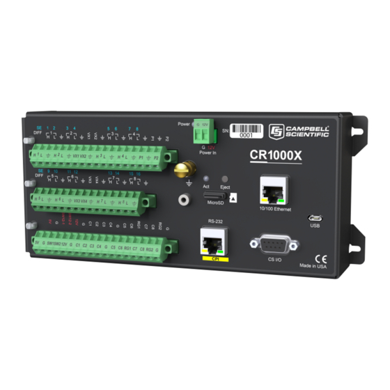
RS-485 The CR1000X Datalogger The CR1000X is used in a broad range of measurement and control functions. Rugged enough for extreme conditions and reliable enough for remote environments, it is also robust enough for complex configurations. Used in applications all over the world, it is a powerful core component for your data acquisition system. -
Page 10: Operations
The CR1000X can simultaneously provide measurement and communication functions. Low power consumption allows the CR1000X to operate for extended time on a battery recharged with a solar panel, eliminating the need for ac power. The CR1000X suspends execution when primary power drops below 9.6 V, reducing the possibility of inaccurate measurements. - Page 11 Analog Input Functions 9 10 11 12 13 14 15 16 DIFF ⌐1¬ ⌐2¬ ⌐3¬ ⌐4¬ ⌐5¬ ⌐6¬ ⌐7¬ ⌐8¬ VX1-VX4 RG1 RG2 Single-Ended Voltage ✔ ✔ ✔ ✔ ✔ ✔ ✔ ✔ ✔ ✔ ✔ ✔ ✔ ✔ ✔ ✔ Differential Voltage Current Loop ✔...
-
Page 12: Power Input
If external alkaline power is used, the alkaline battery pack is connected directly to the POWER IN port. The CR1000X can receive power via the POWER IN port as well as 5 Vdc via a USB connection. If both POWER IN and USB are connected, power will be supplied by whichever has the highest voltage. If USB is the only power source, then the CS I/O port and the 12V, SW12, and 5V terminals will not be operational. -
Page 13: Power Output
12 Vdc during measurement. Voltage on a SW12 terminal will change with datalogger supply voltage. CRBasic instruction SW12() controls the SW12 terminal. • CS I/O port: used to communicate with and often supply power to Campbell Scientific peripheral devices Caution: Voltage levels at the 12V and switched SW12 terminals, and pin 8 on the CS I/O port, are tied closely to the voltage levels of the main power supply. -
Page 14: Grounds
A good earth (chassis) ground will minimize damage to the datalogger and sensors by providing a low- resistance path around the system to a point of low potential. Campbell Scientific recommends that all dataloggers be earth (chassis) grounded. All components of the system (dataloggers, sensors, external power supplies, mounts, housings, etc.) should be referenced to one common earth (chassis) ground. -
Page 15: Communication Ports
• Smart sensors • Modbus and DNP3 networks • Ethernet • Modems • Campbell Scientific PakBus networks • Other Campbell Scientific dataloggers Campbell Scientific datalogger communication ports include: • CS I/O • RS-232/CPI • USB • Ethernet • C1-C8 terminals... - Page 16 It consists of a physical layer definition and a data protocol. CDM devices are similar to Campbell Scientific SDM devices in concept, but the use of the CPI bus enables higher data-throughput rates and use of longer cables. CDM devices require more power to operate in general than do SDM devices.
-
Page 17: Programmable Logic Control
PROGRAMMABLE LOGIC CONTROL The datalogger can control instruments and devices such as: • Controlling wireless cellular modem or GPS receiver to conserve power. • Triggering a water sampler to collect a sample. • Triggering a camera to take a picture. •... - Page 18 Example: Turn Modem on for 10 Minutes Hourly In the case of a cell modem, control is based on time. The modem requires 12 Vdc power, so connect its power wire to a datalogger SW12 terminal. The following code snip turns the modem on for the first ten minutes of every hour using the TimeIsBetween() instruction embedded in an If/Then logic statement: TimeIsBetween(0,10,60,Min)
-
Page 19: Setting Up The Datalogger
4. If prompted, select the Direct Connect connection type and click Next. 5. If this is the first time connecting this computer to a CR1000X via USB, click the Install USB Driver button, select your datalogger, click Install, and follow the prompts to install the USB drivers. -
Page 20: Configuring Settings To Communicate Over Ethernet
CONFIGURING SETTINGS TO COMMUNICATE OVER ETHERNET The CR1000X offers a 10/100 Ethernet connection you can configure using Device Configuration Utility. You will use this utility to enter the datalogger IP Address, Subnet Mask, and IP Gateway address. After this, you can use the EZSetup Wizard to set up communications with the datalogger (see "Configuring... - Page 21 Note: PC200W does not allow IP connections. 2. Click Next. 3. Select the CR1000X Series from the list, type a name for your datalogger (for example, a site or project name), and click Next. 4. Select the IP Port connection type and click Next.
-
Page 22: Testing Communication And Completing Ez Setup
5. Supply power to the datalogger. A USB connection supplies 5V power (as well as a communication link), which is adequate for setup, but a 12V battery will be needed for field deployment. If powering via USB, first install USB drivers during EZ Setup or by using Device Configuration Utility (select your datalogger, then on the main page, click Install USB Driver). -
Page 23: Connecting The Datalogger To A Computer
3. With a successful connection, the Datalogger Clock window displays the time for both the datalogger and the computer. • The Adjusted Server Date/Time displays the current reading of the clock for the computer or server running your datalogger support software. If the Datalogger Date/Time and Adjusted Server Date/Time don't match, you can set the datalogger clock to the Adjusted Server Date/Time by clicking Set Datalogger Clock. - Page 24 Select 50 Hz Noise Rejection for most of the Eastern Hemisphere and areas that operate at 50 Hz. A second prompt lists sensor support options. Campbell Scientific, Inc. (US) is probably the best fit if you are outside Europe. To change the noise rejection or sensor support option for future programs, use the Program menu.
-
Page 25: Sending A Program To The Datalogger
Short Cut. Sending a Program to the Datalogger The CR1000X datalogger requires a CRBasic program to direct measurement, processing, control, and data storage operations. The program file may use the extension .CR1x or .dld. A good practice is to always retrieve data from the datalogger before sending a program; otherwise, data may be lost. -
Page 26: Working With Data
Working with Data By default, the datalogger includes three tables: Public, Status, and DataTableInfo. Each of these tables only contains the most recent measurements and information. • The Public table contains the measurements as they are made. It is updated at the scan interval set within the datalogger program. -
Page 27: Collecting Data
Collecting Data The datalogger writes to data tables according to the schedule set within the CRBasic program (see "Creating Data Tables in a Program" on page 23 for more information). After the program has been running for enough time to generate data records, data may be collected and reviewed via your datalogger support software. -
Page 28: About Data Tables
You can retrieve data based on a schedule or by manually choosing to collect data using datalogger support software (see "Collecting Data" on page 20). The number of data tables is limited to 250. Example of a typical data table TOA5, MyStation, CR1000X, 142, CRxxx.Std.01, CPU:MyTemperature.CR1X, 1958, OneMin TIMESTAMP RECORD BattV_Avg... -
Page 29: Second Header Row
• 5: CRxxx.Std.01 - Datalogger OS version. Changed via installation of a new OS. • 6: CPU:MyTemperature.CR1X - Datalogger program name. Changed by sending a new program (see "Sending a Program to the Datalogger" on page 18 for more information). •... -
Page 30: Data Records
• WindVector WVc • Median Med • ET ETsz • Solar Radiation (from ET) RSo • Time of Max TMx • Time of Min TMn Hst is reported in the form Hst,20,1.0000e+00,0.0000e+00,1.0000e+01 where Hst denotes a histogram, 20 = 20 bins, 1 = weighting factor, 0 = lower bound, 10 = upper bound. -
Page 31: Memory And Data Storage
Data table SRAM and the CPU drive are automatically partitioned for use in the datalogger. The USR drive can be partitioned as needed. The USB drive is automatically partitioned when a Campbell Scientific mass-storage device is connected. The CRD drive is automatically partitioned when a memory card is installed. -
Page 32: Microsd (Crd: Drive) Storage
The CRD: drive uses microSD cards exclusively. Its primary purpose is the storage of data files in a compact binary format. Campbell Scientific recommends and supports only the use of microSD cards obtained from Campbell Scientific. These cards are industrial-grade and have passed Campbell Scientific hardware testing. -
Page 33: Managing Memory Via Powerup.ini
Because of the way the FAT32 card format works, you can avoid long datalogger compile times with a freshly formatted card by first formatting the new card on a computer, then copying a small file to the card from the computer, and then deleting the file with the computer. When the small file is copied to the card, the computer updates a sector on the card that which allows the datalogger program to compile faster. - Page 34 Syntax Syntax for powerup.ini is: Command,File,Device where, • Command is one of the numeric commands in the following table. • File is the accompanying operating system or user program file. File name can be up to 22 characters long. • Device is the datalogger memory drive to which the accompanying operating system or user program file is copied (usually CPU).
- Page 35 5,,usr: Example: Send OS on Power Up 'Load an operating system (.obj) file into FLASH as the new OS 9,CR1000X.Std.01.obj Example: Run Program from SC115 Flash Memory Drive 'A program file is carried on an SC115 Flash Memory drive. 'Do not copy program file from SC115. Run program always, erase data.
-
Page 36: Measurements
For example, single-ended channel 1 is comprised of terminals SE 1 and . Single-ended terminals are labeled in blue. For more information, see "CR1000X Wiring Panel" on page 3. The single-ended configuration is used with the following CRBasic instructions: • VoltSE() •... -
Page 37: Differential Measurements
A differential measurement measures the difference in voltage between two input terminals. For example, DIFF channel 1 is comprised of terminals 1H and 1L, with 1H as high and 1L as low. For more information, see "CR1000X Wiring Panel" on page 3. The differential configuration is used with the following CRBasic instructions: •... - Page 38 Sensor Type Connection Example 2-wire transmitter using external power 3-wire transmitter using datalogger power 3-wire transmitter using external power 4-wire transmitter using datalogger power 4-wire transmitter using external power See also "Current Measurements Specifications" on page 83. Measurements...
-
Page 39: Ratiometric Resistance Measurements
Ratiometric Resistance Measurements Bridge resistance is determined by measuring the difference between a known voltage applied to the excitation (input) of a resistor bridge and the voltage measured on the output arm. The datalogger supplies a precise voltage excitation via VX terminals. Return voltage is measured on analog input terminals configured for single-ended (SE) or differential (DIFF) input. - Page 40 Fundamental Relationship: Key: V = excitation voltage; V = sensor return voltages; R = fixed, bridge or completion resistor; R = variable or sensing resistor. Campbell Scientific offers a list of available terminal input modules to facilitate this measurement. Measurements...
-
Page 41: Resistive-Bridge Measurements And Voltage Excitation
RESISTIVE-BRIDGE MEASUREMENTS AND VOLTAGE EXCITATION Offset voltage compensation applies to bridge measurements. In addition to RevDiff and MeasOff parameters discussed in "Minimizing Offset Voltages" on page 72, CRBasic bridge measurement instructions include the RevEx parameter that provides the option to program a second set of measurements with the excitation polarity reversed. - Page 42 elements in the full-bridge schematic. In other words, a quarter-bridge strain gage has one active element, a half-bridge has two, and a full-bridge has four. StrainCalc() requires a bridge-configuration code. The following table shows the equation used by each configuration code. Each code can be preceded by a dash (-). Use a code without the dash when the bridge is configured so the output decreases with increasing strain.
-
Page 43: Ac Excitation
• Voltage Measurement Accuracy, Self- Calibration, and Ratiometric Measurements Note: Error discussed in this section and error-related specifications of the CR1000X do not include error introduced by the sensor or by the transmission of the sensor signal to the datalogger. -
Page 44: Period-Averaging Measurements
device, such as the datalogger. These connections form the reference junction. If the two junctions (measurement and reference) are at different temperatures, a voltage proportional to the difference is induced in the wires. This phenomenon is known as the Seebeck effect. Measurement of the voltage between the positive and negative terminals of the voltage-measurement device provides a direct measure of the temperature difference between the measurement and reference junctions. -
Page 45: Low-Level Ac Measurements
The datalogger includes terminals that are configurable for pulse input to measure counts or frequency as shown in the following image. Pulse input terminals and the input types they can measure: Input Type Pulse Input Terminal Data Option High-frequency • Counts C (all) •... -
Page 46: High Frequency Measurements
Low-level ac signals cannot be measured directly by C terminals. Peripheral terminal expansion modules are available for converting low-level ac signals to square-wave signals measurable by C terminals. For more information, see "Pulse Counting Specifications" on page 82. HIGH FREQUENCY MEASUREMENTS High-frequency (square-wave) signals can be measured on P or C terminals. -
Page 47: Edge Timing And Edge Counting
Switch Closure on Terminal Open Collector on Terminal C Terminals Switch-closure mode is a special case edge-count function that measures dry-contact switch-closures or open collectors. The operating system filters bounces. • CRBasic instruction: PulseCount() See also "Pulse Counting Specifications" on page 82. EDGE TIMING AND EDGE COUNTING Edge time, period, and counts can be measured on P or C terminals. -
Page 48: Pulse Measurement Tips
PULSE MEASUREMENT TIPS The PulseCount() instruction uses dedicated 32-bit counters to accumulate all counts over the programmed scan interval. The resolution of pulse counters is one count or 1 Hz. Counters are read at the beginning of each scan and then cleared. Counters will overflow if accumulated counts exceed 4,294,967,296 (2 ), resulting in erroneous measurements. -
Page 49: Vibrating Wire Measurements
A thermistor included in most sensors can be measured to compensate for temperature errors. Measuring the resonant frequency by means of period averaging is the classic technique, but Campbell Scientific has developed static and dynamic spectral-analysis techniques (VSPECT) that produce superior noise rejection, higher resolution, diagnostic data, and, in the case of dynamic VSPECT, measurements up to 333.3 Hz. -
Page 50: Communication Protocols
PakBus, Modbus, DNP3, CPI, SPI, and TCP/IP. Several industry- specific protocols are also supported. CAN bus is supported when using the Campbell Scientific SDM- CAN communication module. See also "Communications Specifications" on page 84. -
Page 51: Modbus Communications
How to Access Live Measurement Data Using Modbus • Using Campbell Scientific Dataloggers as Modbus Slave Devices in a SCADA Network Because Modbus has a set command structure, programming the datalogger to get data from field instruments is much simpler than from serial sensors. Because Modbus uses a common bus and addresses each node, field instruments are effectively multiplexed to a datalogger without additional hardware. -
Page 52: Internet Communications
Settings Editor: Ethernet | {information box} to see the assigned IP address. The CR1000X provides a DNS client that can query a DNS server to determine if an IP address has been mapped to a hostname. If it has, then the hostname can be used interchangeably with the IP address in some datalogger instructions. -
Page 53: Pakbus Communications
• Routing - the datalogger can act as a router, passing on messages intended for another Campbell Scientific datalogger. PakBus supports automatic route detection and selection. • Short distance networks - a datalogger can talk to another datalogger over distances up to 30 feet by connecting transmit, receive, and ground wires between the dataloggers. -
Page 54: Sdi-12 Transparent Mode
To enter the SDI-12 transparent mode, enter the datalogger support software terminal emulator: 1. Press Enter until the datalogger responds with the prompt CR1000X>. 2. Type SDI12 at the prompt and press Enter. In response, the query Enter Cx Port is presented with a list of available ports. Enter the port number assigned to the terminal to which the SDI-12 sensor is connected, and press Enter. -
Page 55: Sdi-12 Programmed Mode/Recorder Mode
SDI-12 sensor. A common use of this feature is the transfer of data from the datalogger to other Campbell Scientific dataloggers over a single-wire interface (terminal configured for SDI-12 to terminal configured for SDI-12), or to transfer data to a third-party SDI-12 recorder. -
Page 56: Sdi-12 Power Considerations
SDI-12 POWER CONSIDERATIONS When a command is sent by the datalogger to an SDI-12 probe, all probes on the same SDI-12 port will wake up. However, only the probe addressed by the datalogger will respond. All other probes will remain active until the timeout period expires. Example: Probe: Water Content Power Usage:... -
Page 57: Maintaining Your Datalogger
If sending the datalogger to Campbell Scientific for calibration or repair, consult first with Campbell Scientific. If the datalogger is malfunctioning, be prepared to perform some troubleshooting procedures (see "Troubleshooting the Datalogger"... -
Page 58: Datalogger Security
operational temperature range is specified as less accurate by a factor of 10. That is, over the extended temperature range of –55 °C to 85 °C, the accuracy specification of ±0.08 % of reading can degrade to ±0.8 % of reading with background calibration disabled. If the temperature of the datalogger remains the same, there is little calibration drift if background calibration is disabled. -
Page 59: Security Codes
SECURITY CODES The datalogger employs a security scheme that includes three levels of security. Security codes can effectively lock out innocent tinkering and discourage wannabe hackers on non-IP based communication links. However, any serious hacker with physical access to the datalogger or to the communications hardware can, with only minimal trouble, overcome the five-digit security codes. -
Page 60: Datalogger Enclosures
1. Insert the included nylon anchors into the backplate. Position them to align with the mounting holes on the base of the CR1000X. 2. Holding the CR1000X to the backplate, screw the screws into the nylon anchors. Internal Battery The lithium battery powers the internal clock and SRAM when the datalogger is not powered. This voltage is displayed in the LithiumBattery field in the Status table. -
Page 61: Internal Lithium Battery Specifications
• Time. Clock will need resetting when the battery is replaced. • Final-memory data tables. A replacement lithium battery can be purchased from Campbell Scientific or another supplier. See "Power Requirements" on page 77 for more information. Warning: Misuse or improper installation of the internal lithium battery can cause severe injury. -
Page 62: Replacing The Internal Battery
REPLACING THE INTERNAL BATTERY It is recommended that you send the datalogger in for scheduled calibration, which includes internal battery replacement (see "Datalogger Calibration" on page 50). Warning: Any damage made to the datalogger during replacement of the internal battery is not covered under warranty. -
Page 63: Electrostatic Discharge And Lightning Protection
Secondary strikes induce voltage in power lines or wires connected to instrumentation. While elaborate, expensive, and nearly infallible lightning protection systems are on the market, Campbell Scientific, for many years, has employed a simple and inexpensive design that protects most systems in most circumstances. -
Page 64: Power Budgeting
• "Power Requirements" on page 77 • "Power Output Specifications" on page 78 Updating the Operating System Campbell Scientific posts operating system (OS) updates at www.campbellsci.com/downloads when they become available. Before deploying instruments, check operating system versions and update as needed. - Page 65 • Any peripherals being powered through the SW12 terminals will be turned off until the program logic turns them on again. • Operating systems are very large files. Be cautious of data charges. Sending over a direct serial or USB connection is recommended, when possible. Maintaining Your Datalogger...
-
Page 66: Tips And Troubleshooting
Tips and Troubleshooting The following basic procedure can be used if a system is not operating properly. 1. Using a voltmeter, check the voltage of the primary power source at the POWER IN terminals on the face of the datalogger. 2. -
Page 67: Watchdog Errors
• Many PortSet() instructions back-to-back with no delay. • High-speed serial data on multiple ports with very large data packets or bursts of data. If any of these are not the apparent cause, contact Campbell Scientific for assistance (see https://www.campbellsci.com/repair). Causes that may require assistance include: •... -
Page 68: Time Keeping
expression that is undefined. NAN indicates an invalid measurement. For more information, see Tips and Tricks: Who's NAN? NANs are expected in the following conditions: • Input signals exceed the voltage range chosen for the measurement. • An invalid SDI-12 command is sent •... -
Page 69: Time Stamps
The ClockChange instruction can be used to: • Detect, track, and log externally triggered clock change events. • Characterize the jitter in your clock-syncing method. TIME STAMPS A measurement without an accurate time reference has little meaning. Data on the datalogger are stored with time stamps. -
Page 70: Program Compiles But Does Not Run Correctly
• The datalogger has a different operating system that is not fully compatible with the computer compiler. Check the two versions if in doubt. The computer compiler version is shown on the first line of the compile results. Update the computer compiler by first downloading the executable OS file from www.campbellsci.com. -
Page 71: Program Send Reset
When a program compiles, all variables are initialized. A program is recompiled after a power failure or a manual stop. For instances that require variables to be preserved through a program recompile, the CR1000X has the PreserveVariables() instruction. MANUAL DATA TABLE RESET Data table memory is selectively reset from: •... -
Page 72: Minimizing Ground Loop Errors
Note that the geometry of the electrodes has a great effect on the magnitude of this error. The Delmhorst gypsum block used in the Campbell Scientific 227 probe has two concentric cylindrical electrodes. The center Tips and Troubleshooting... -
Page 73: Improving Voltage Measurement Quality
Campbell Scientific resistive soil probes and conductivity probes are built with series capacitors to block this dc current. In addition to preventing sensor deterioration, the capacitors block any dc component from affecting the measurement. -
Page 74: Minimizing Ground Potential Differences
• Rapid sampling is required. Single-ended measurement time is about half that of differential measurement time. • Sensor is not designed for differential measurements. Many Campbell Scientific sensors are not designed for differential measurement, but the drawbacks of a single-ended measurement are usually mitigated by large programmed excitation and/or sensor output voltages. -
Page 75: Detecting Open Inputs
Ground potential differences are a common problem when measuring full-bridge sensors (strain gages, pressure transducers, etc), and when measuring thermocouples in soil. • Soil Temperature Thermocouple: If the measuring junction of a thermocouple is not insulated when in soil or water, and the potential of earth ground is, for example, 1 mV greater at the sensor than at the point where the datalogger is grounded, the measured voltage is 1 mV greater than the thermocouple output. -
Page 76: Minimizing Settling Errors
The datalogger includes fN1 digital filtering, which serves two purposes: • Arrive as close as possible to the true input signal • Filter out measurement noise at specific frequencies, the most common being noise at 50 Hz or 60 Hz, which originate from mains-power lines. Filtering time is inversely proportional to the frequency being filtered. - Page 77 Measuring Settling Time Settling time for a particular sensor and cable can be measured with the CR1000X. Programming a series of measurements with increasing settling times will yield data that indicate at what settling time a further increase results in negligible change in the measured voltage. The programmed settling time at this point indicates the settling time needed for the sensor / cable combination.
-
Page 78: Factors Affecting Accuracy
The first six measurements are shown in the following table: Timestamp PT(1) PT(2) PT(3) PT(4) PT(5) PT(6) 8/3/2017 23:34 0.03638599 0.03901386 0.04022673 0.04042887 0.04103531 0.04123745 8/3/2017 23:34 0.03658813 0.03921601 0.04002459 0.04042887 0.04103531 0.0414396 8/3/2017 23:34 0.03638599 0.03941815 0.04002459 0.04063102 0.04042887 0.04123745 8/3/2017 23:34 0.03658813... -
Page 79: Minimizing Offset Voltages
Single-ended measurements are susceptible to voltage drop at the ground terminal caused by return currents from another device that is powered from the CR1000X wiring panel, such as another manufacturer's communication modem, or a sensor that requires a lot of power. Currents >5 mA are usually undesirable. - Page 80 CR1000X moves to the next measurement. However, if the CRBasic program is written in such a way that an excitation terminal is enabled during an unrelated measurement of a small voltage, an offset error may occur.
- Page 81 True programs the measurement for excitation reversal. Excitation reversal results in a polarity change of the measured voltage so that two measurements with opposite polarity can be subtracted and divided by 2 for offset reduction similar to input reversal for differential measurements. For example, if 3 µV offset exists in the measurement circuitry, a 5 mV signal is measured as 5.003 mV.
-
Page 82: File System Error Codes
self-calibration. For installations experiencing fluctuating offset voltages, choosing MeasOff = True for the VoltSE() instruction results in better offset voltage performance. If RevDiff, RevEx, or MeasOff is disabled (= False), offset voltage compensation is automatically performed, albeit less effectively, by using measurements from the background calibration. Disabling RevDiff, RevEx, or MeasOff speeds up measurement time;... -
Page 83: File Name And Resource Errors
35 DMA memory boundary crossing error 36 Miscellaneous I/O error 37 Pipe size of 0 requested 38 Memory-release error (relmem) 39 FAT sectors unreadable (all copies) 40 Bad BPB sector 41 Time-out waiting for filesystem available 42 Controller failure error 43 Pathname exceeds _MAX_PATHNAME File Name and Resource Errors The maximum size of the file name that can be stored, run as a program, or FTP transferred in the... -
Page 84: Specifications
Extended electrical specifications (noted as XT in specifications) are valid over a -55 to +85 °C non-condensing environment. Recalibration recommended every three years. Critical specifications and system configuration should be confirmed with Campbell Scientific before purchase. System Specifications .......................... 77 Physical Specifications ........................ -
Page 85: Ground Specifications
• 30 Vdc sustained voltage limit without damage. Transient voltage suppressor (TVS) diodes at the Power In terminal clamps transients to 36 to 40 V. Input voltages greater than 18 V and less than 32 V are tolerated; however, the 12 V output SW12-1 and SW12-2 are disabled and will not function until the input voltage falls below 16 V. - Page 86 a hold current limited to 1.3 A @ -40°C, 0.47 A @ 80°C. See the VX terminal information for additional regulated voltage outputs. Terminal Source Limit 1310 mA @ –40 °C 1040 mA @ 0 °C 900 mA @ 20 °C SW12-1 SW12-2 690 mA @ 50 °C...
-
Page 87: Analog Specifications
Analog Specifications 16 single-ended (SE) or 8 differential (DIFF) inputs individually configurable for voltage, thermocouple, ratiometric, and period average measurements, using a 24-bit ADC. One channel at a time is measured in numeric succession. VOLTAGE MEASUREMENTS Input Resistance: 20 GΩ Input Limits: ±5 V Sustained Input Voltage without Damage: ±20 Vdc Dc Common Mode Rejection:... -
Page 88: Ratiometric-Resistance Measurements Specifications
Multiplexed Measurement Time: (450 µs + settling time + (1/fN1)) • reps (Default settling time of 500 µs. These are not maximum speeds. Multiplexed denotes circuitry inside the datalogger that switches signals into the ADC.) Multiplexed Measurement Time (ms) with 500 µs Settling Time: Differential Single-Ended or Differential with Input Reversal... -
Page 89: Current Measurements Specifications
Current Measurements Specifications The datalogger makes current loop measurements by measuring across a current-sense resistor associated with the RS-485 resistive ground terminals RG1 & RG2. Maximum Input Voltage: ±16 V Resistance to Ground: 101 Ω Current Measurement Shunt Resistance: 10 Ω Maximum Current Measurement Range: ±80 mA Absolute Maximum Current: ±160 mA Current Measurement Resolution: ≤... -
Page 90: Digital I/O Specifications
Low-Level Ac Pulse Input Ranges: • Sine Wave Input 20 mV RMS, Input Frequency Range 1.0 to 20 Hz • Sine Wave Input 200 mV RMS, Input Frequency Range 0.5 to 200 Hz • Sine Wave Input 2000 mV RMS, Input Frequency Range 0.3 to 10,000 Hz •... -
Page 91: High-Frequency Input
DNP3, NTCIP, NMEA 0183, I2C, SPI, custom user definable over serial, UDP Data File Formats: CSV, XML, JSON, binary, encrypted, custom user definable USB: Micro-B device for computer connectivity CS I/O: 9-pin D-sub multidrop interface to interface with Campbell Scientific CS I/O peripherals CS I/O Pinout: Function... -
Page 92: Standards Compliance Specifications
115200. RS-232/CPI: Single RJ45 module port that can operate in one of two modes: RS-232 or CPI. RS-232 is used to connect computer, sensor, or communication devices serially. CPI is used to connect Campbell Scientific CDM measurement peripherals and sensors. -
Page 93: Support
Support Product Assistance For technical assistance with Campbell Scientific equipment, go to www.campbellsci.com/support, or contact technical support at 435-227-9100. For repair and calibration services, visit www.campbellsci.com/repair. Precautions DANGER — MANY HAZARDS ARE ASSOCIATED WITH INSTALLING, USING, MAINTAINING, AND WORKING ON OR AROUND TRIPODS, TOWERS, AND ANY ATTACHMENTS TO TRIPODS AND TOWERS SUCH AS SENSORS, CROSSARMS, ENCLOSURES, ANTENNAS, ETC. -
Page 94: Warranty
• When primary power is NOT connected to the datalogger, the battery will last about three years. • See "Internal Battery" on page 53 for more information. IMPORTANT: Maintain a level of calibration appropriate to the application. Campbell Scientific recommends factory recalibration of the datalogger every three years. -
Page 95: Acknowledgements
Acknowledgements lwIP Copyright (c) 2001-2004 Swedish Institute of Computer Science. All rights reserved. Redistribution and use in source and binary forms, with or without modification, are permitted provided that the following conditions are met: 1. Redistributions of source code must retain the above copyright notice, this list of conditions and the following disclaimer. -
Page 96: Glossary
Glossary Alternating current (see Vac). accuracy The degree to which the result of a measurement, calculation, or specification conforms to the correct value or a standard. Analog to digital conversion. The process that translates analog voltage levels to digital values. amperes (A) Base unit for electric current. - Page 97 Scientific CDM peripheral devices. It consists of a physical layer definition and a data protocol. CDM devices are similar to Campbell Scientific SDM devices in concept, but the use of the CPI bus enables higher data- throughput rates and use of longer cables. CDM devices require more power to operate in general than do SDM devices.
- Page 98 <underscore> ( _), is 512 characters. A command line usually consists of one program statement, but it may consist of mulitple program statements separated by a <colon> (:). CompactFlash CompactFlash® (CF) is a memory-card technology used in some Campbell Scientific card-storage modules. compile The software process of converting human-readable program code to binary machine code. Datalogger user programs are compiled internally by the datlogger operating system.
- Page 99 CPU, USR, CRD, and USB memory drives, and in binary or ASCII files that result from collecting final-storage memory with datalogger support software. datalogger support software LoggerNet, PC400, and PC200W - these Campbell Scientific software applications includes at least the following functions: datalogger communications, downloading programs, clock setting, and retrieval of measurement data.
- Page 100 differential A sensor or measurement terminal wherein the analog voltage signal is carried on two leads. The phenomenon measured is proportional to the difference in voltage between the two leads. A CRBasic command for declaring and dimensioning variables. Variables declared with Dim remain hidden during datalogger operations.
- Page 101 execution time Time required to execute an instruction or group of instructions. If the execution time of a program exceeds the Scan() Interval, the program is executed less frequently than programmed and the Status table SkippedScan field will increment. expression A series of words, operators, or numbers that produce a value or result.
- Page 102 full-duplex A serial communication protocol. Simultaneous bi-directional communications. Communications between a serial port and a computer is typically full duplex. garbage The refuse of the data communication world. When data are sent or received incorrectly (there are numerous reasons why this happens), a string of invalid, meaningless characters (garbage) often results. Two common causes are: 1) a baud-rate mismatch and 2) synchronous data being sent to an asynchronous device and vice versa.
- Page 103 Using opto-couplers in a connecting device allows communication signals to pass, but breaks alternate ground paths and may filter some electromagnetic noise. Campbell Scientific offers optically isolated RS-232 to CS I/O interfaces as an accessory for use on the CS I/O port.
- Page 104 LoggerLink Mobile applications that allow a mobile device to communicate with IP, wi-fi, or Bluetooth enabled dataloggers. LoggerNet Campbell Scientific's datalogger support software for programming, communication, and data retrieval between dataloggers and a computer. LONG Data type used when declaring integers.
- Page 105 Device in a PakBus network that communicate directly with a device without being routed through an intermediate device. Network Planner Campbell Scientific software designed to help set up dataloggers in PakBus networks so that they can communicate with each other and the LoggerNet server. For more information, see https://www.campbellsci.com/loggernet.
- Page 106 PakBusGraph Software that shows the relationship of various nodes in a PakBus network and allows for monitoring and adjustment of some registers in each node. A PakBus node is typically a Campbell Scientific datalogger, a computer, or a communication device.
- Page 107 parameter Part of a procedure (or command) definition. PC200W Basic datalogger support software for direct connect. It supports a connection between computer and datalogger and includes Short Cut for creating datalogger programs. Tools for setting the datalogger clock, sending programs, monitoring sensors, and on-site viewing and collection of data are also included. PC400 Datalogger support software that supports a variety of communication options, manual data collection, and data monitoring displays.
- Page 108 A setting, a Status table element, or a DataTableInformation table element. Also a device for conditioning an electrical power source. Campbell Scientific regulators typically condition ac or dc voltages greater than 16 Vdc to about 14 Vdc. Reset Tables command Reset Tables command resets data tables configured for fill and stop.
- Page 109 Recommended Standard 232. A loose standard defining how two computing devices can communicate with each other. The implementation of RS-232 in Campbell Scientific dataloggers to computer communications is quite rigid, but transparent to most users. Features in the datalogger that implement RS-232 communication with smart sensors are flexible.
- Page 110 Software Development Kit Synchronous Device for Measurement. A processor-based peripheral device or sensor that communicates with the datalogger via hardwire over a short distance using a protocol proprietary to Campbell Scientific. Seebeck effect Induces microvolt level thermal electromotive forces (EMF) across junctions of dissimilar metals in the presence of temperature gradients.
- Page 111 A datum or variable consisting of alphanumeric characters. support software Campbell Scientific software that includes at least the following functions: datalogger communications, downloading programs, clock setting, and retrieval of measurement data. synchronous The transmission of data between a transmitting and a receiving device occurs as a series of zeros and ones.
- Page 112 A command-line shell that facilitates the issuance of low-level commands to a datalogger or some other compatible device. A terminal emulator is available in most datalogger support software available from Campbell Scientific. thermistor A thermistor is a temperature measurement device with a resistive element that changes in resistance with temperature.
- Page 113 WatchdogTimer entry of the Status table. A low number (1 to 10) of watchdog timer resets is of concern, but normally indicates that the situation should just be monitored. A large number of errors (>10) accumulating over a short period indicates a hardware or software problem. Consult with a Campbell Scientific support engineer.
- Page 114 Index example program ..........23 instructions ............23 accuracy factors ........36, 71 memory .............. 63 auto self-calibration ........50 datalogger clock ........13, 15 dataloggers current status ............. 59 bandwidth ............43 maintenance ............50 battery ............53 protection ............53 voltage status ............
- Page 115 lightening protection ........56 12V ................6 5V ................6 lithium battery ..........53 budgeting ............57 low-level ac measurements......38 ground ..............7 LVTTL .............. 9 I/O .................5 inputs..............5 noise..............68 maintenance ..........50 output ..............6 max time online ........13, 15 supplies .............5, 57, 64 measurements USB ...............5...
- Page 116 signal ground ........... 7 SE .................5 VX .................5 signal settling ..........69 testing communication ........15 single-ended measurments ...... 29, 66 thermocouple measurements ......36 sink limits ............6 time skipped records ..........59 keeping............... 61 skpped scans ..........59 skew ..............
Need help?
Do you have a question about the CR1000X and is the answer not in the manual?
Questions and answers
Please provide detailed explanation how CR1000X to install and monitor the Cathodic protection on test stations of pipelines?