
Related Manuals for Campbell CRVW3 Series


Summary of Contents for Campbell CRVW3 Series
- Page 1 CRVW3 3-Channel Vibrating-Wire Datalogger Revision: 1/18 C o p y r i g h t © 2 0 1 5 - 2 0 1 8 C a m p b e l l S c i e n t i f i c , I n c .
- Page 4 (780) 454-2655. Campbell Scientific (Canada) Corp. is unable to process any returns until we receive this form. If the form is not received within three days of product receipt or is incomplete, the product will be returned to the client at the client’s expense.
- Page 5 Periodically (at least yearly) check electrical ground connections. WHILE EVERY ATTEMPT IS MADE TO EMBODY THE HIGHEST DEGREE OF SAFETY IN ALL CAMPBELL SCIENTIFIC PRODUCTS, THE CLIENT ASSUMES ALL RISK FROM ANY INJURY RESULTING FROM IMPROPER INSTALLATION, USE, OR MAINTENANCE OF TRIPODS, TOWERS, OR ATTACHMENTS TO TRIPODS AND TOWERS SUCH AS SENSORS, CROSSARMS, ENCLOSURES, ANTENNAS, ETC.
- Page 6 PLEASE READ FIRST About this manual Please note that this manual was originally produced by Campbell Scientific Inc. (CSI) primarily for the US market. Some spellings, weights and measures may reflect this origin. Some useful conversion factors: Area: 1 in...
-
Page 8: Table Of Contents
Table of Contents PDF viewers: These page numbers refer to the printed version of this document. Use the PDF reader bookmarks tab for links to specific sections. 1. Introduction ..............1 2. Precautions ..............4 3. Initial Inspection ............5 4. - Page 9 Table of Contents 8.2.2 Providing Power to the CRVW3 ..........36 8.2.2.1 Alkaline D-Cell Option (–ALK) ........36 8.2.2.2 Rechargeable Battery Option (–RC) ........ 37 8.2.2.3 Grid Power............... 39 8.2.3 Humidity Monitoring and Control ..........40 8.2.4 Mounting the CRVW3 Enclosure ..........40 8.2.5 Installing the CRVW3 Antenna ..........
- Page 10 Table of Contents 10.2.8.2 Plan Validation with Others ..........72 10.2.8.3 Hardware Procurement ............. 72 10.3 Deployment Strategy................72 10.3.1 Radio Network Lab Validation ........... 72 10.3.2 Field Deployment Considerations ..........73 10.4 Deployment of CRVW3 Radio Stations ..........74 10.4.1 CRVW3-RF451 Deployment ............
- Page 11 Table of Contents Aggregator Station Configuration ........... C-1 Programming the Aggregator ............C-2 D. GetDataRecord Sample Program ......D-1 E. Engineering Output and Calibration ..... E-1 Engineering Output ................E-1 Calibration of Sensors ..............E-2 F. ESD Testing ............F-1 Figures 1-1.
- Page 12 Table of Contents Table 8-1. CRVW3 LED Behavior ..............46 CRBasic Example D-1. Using GetDataRecord to Extract Data From a CRVW3 ....D-1...
- Page 13 Table of Contents...
-
Page 14: Introduction
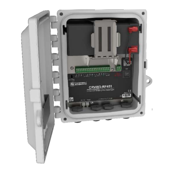
CRVW3 3-Channel Vibrating-Wire Datalogger Introduction The CRVW3 is a datalogger (Campbell recorder) that measures and stores readings from up to three vibrating-wire sensors. A temperature measurement (usually obtained from a thermistor built-in to the sensor) is also available for each of these three channels. Standard, single-coil-circuit vibrating-wire sensors are supported (purchased separately). -
Page 15: The Crvw3-Ne 3-Channel Vibrating-Wire Datalogger
United States and Canada. (FCC / IC / IFT compliant) The RF451 can also be used in Australia and New Zealand but must be purchased directly from Campbell Scientific Australia to ensure that it is properly configured and badged for ACMA... - Page 16 No CRBasic programming is required. Frequency and temperature measurements are obtained at the specified measurement interval. Optional engineering output can be calculated using advanced settings. Additional information about the CRVW3 can be found on the Campbell Scientific website: www.campbellsci.com/crvw3 Before using the CRVW3, please refer to the following: •...
-
Page 17: Precautions
(in addition to those built-in to the CRVW3) to operate as the base radio station in the network. Please consult with your local Campbell Scientific support representative regarding the use of radio options. Also refer to Section 9, Radio Networks (p. -
Page 18: Initial Inspection
CRVW3 3-Channel Vibrating-Wire Datalogger Initial Inspection Ensure that the following standard items were included with your shipment of the CRVW3: • USB 2.0 Cable Type A Male to Micro B Male (pn 27555) • Flat-bladed Screwdriver (pn 1113) • Quick Deploy Guide (folded card, pn 31174) Desiccant Bag (pn 4905) •... -
Page 19: Contents Of The -Um Mounting Option
CRVW3 3-Channel Vibrating-Wire Datalogger If the –UM mounting option was selected, ensure that the corresponding mounting hardware was included with your shipment: Mounting Bracket (2) • U-bolt (2) • Screws (4) • Washers (4) • Lock Washers (4) • Nuts (4) •... -
Page 20: Quickstart
Thoroughly check the packaging material for items that may be trapped inside. In case of damage, file claims with the shipping company. Contact Campbell Scientific to facilitate repair or replacement of damaged items. QuickStart For Quickstart information, refer to the Quick Deploy Guide included with each CRVW3 as a folded card inside the enclosure (pn 31174). -
Page 21: Measurement Theory
CRVW3 3-Channel Vibrating-Wire Datalogger Measurement Theory The CRVW3 uses Campbell Scientific VSPECT™ technology (U.S. Patent No. 7,779,690) to measure standard, single-coil-circuit vibrating-wire sensors. FIGURE 5-2. CRVW3 Cable Connection and Entry Points A vibrating-wire sensor is designed by its manufacturer so that its output corresponds to changes of the phenomenon in the environment being measured. -
Page 22: Time-Series And Frequency Response Of A Vibrating-Wire Sensor
CRVW3 3-Channel Vibrating-Wire Datalogger The CRVW3 excites vibrating-wire sensors with a swept excitation (frequency-rich) waveform. The lowest frequency and highest frequency used in that excitation are customizable by the user. This frequency range represents all expected natural frequencies that the sensor should produce, including those expected when it measures the most extreme conditions in the environment (highest and lowest frequencies). -
Page 23: About This Manual
CRVW3 3-Channel Vibrating-Wire Datalogger About This Manual Please study the remaining sections of this manual to obtain maximum benefit from your CRVW3 dataloggers. Section 6, Specifications , contains key specifications relevant to the (p. 10) measurement and use of the CRVW3. Section 7, Installation , introduces the main installation issues applicable (p. - Page 24 CRVW3 3-Channel Vibrating-Wire Datalogger Vibrating Wire Measurement Excitation Options: 2 V (±1 V), 5 V (±2.5 V), 12 V (±6 V) Measurement (Frequency) Resolution: 0.001 Hz RMS (–40 to 70 °C) Time-series Basic Resolution: 24-bit ADC Measurement Accuracy: ±0.005% of reading (–40 to 70 °C) Measurement Method: VSPECT (Spectral Analysis), U.S.
- Page 25 CRVW3 3-Channel Vibrating-Wire Datalogger Data Transmission Error Detection: 32-bit CRC, retransmit on error Data Encryption: Proprietary spread spectrum technology Link Throughput: 115.2 kbps, max Average Additional Current Transmit: 650 mA (@12 Vdc) Receive: 40 mA (@12 Vdc) Idle: 15 mA (@12 Vdc) Sleep: 6 mA (@12 Vdc) Radio Repeater:...
- Page 26 CRVW3 3-Channel Vibrating-Wire Datalogger Power Charge Terminal: 16 to 28 Vdc from solar panel or dc power converter Battery Options: Rechargeable 7 Ah or 8 D-cell alkaline Physical Weight: 4.2 kg (9.2 lb) with rechargeable battery, 3.0 kg (6.6 lb) with alkaline batteries Operating Temperature Range: –40 to 70 °C...
-
Page 27: Installation
Installation For summarized installation information, refer to the Quick Deploy Guide (pn 31174) included with each CRVW3 as a folded card inside the enclosure. You can also view and download the Quick Deploy Guide from the Campbell Scientific website: s.campbellsci.com/documents/us/manuals/crvw3-quick-deploy-guide.pdf Campbell Scientific Field-Deployment Philosophy Pre-configure and test your measurement system before taking it to the field. -
Page 28: Installation Of Individual Crvw3 Stations
CRVW3 3-Channel Vibrating-Wire Datalogger Installation of Individual CRVW3 Stations The installation of an individual CRVW3 station includes two critical steps: Connecting with and configuring the CRVW3 device in the lab or office (Section 8.1, Lab Connection and Configuration (p. 15) Deployment of the CRVW3 device to a permanent location in the field (Section 8.2, Field Deployment of the CRVW3 (p. -
Page 29: Install The Crvw3 Usb Driver
CRVW3 3-Channel Vibrating-Wire Datalogger This software is also available as a free download from the Campbell scientific website (www.campbellsci.com/downloads, www.campbellsci.com/19_1_9999_83). Check the version of any previously installed DevConfig software to ensure it is version 2.10 or later. If it is an earlier version, it will need to be upgraded using a newer installation program. -
Page 30: Network Planner
CRVW3 3-Channel Vibrating-Wire Datalogger Start DevConfig, and then scroll down and highlight the CRVW Series device and you will see a screen like this: Install the USB driver by clicking on the link entitled “install the USB driver onto your computer”. 8.1.1.3 Network Planner If you have installed the LoggerNet software, you can use the Network Planner tool to make network design decisions and configure devices before they are... -
Page 31: Wiring Temporary Sensors To The Crvw3
CRVW3 3-Channel Vibrating-Wire Datalogger device that is a part of the system. Using a checklist showing each device that requires configuration (Configure Devices), screens similar to those found in DevConfig are used to prepare each device for field use. For more information about the Network Planner, refer to the LoggerNet Manual, Section 4.3. -
Page 32: Wiring Panel Of The Crvw3
CRVW3 3-Channel Vibrating-Wire Datalogger FIGURE 8-1. Wiring Panel of the CRVW3 Two of the sensor leads are for the main vibrating-wire measurement, and they are wired internally to the coil-circuit of the sensor. This connection is used for both sensor excitation (energy input) and for reading out the current measurement (measurement output). -
Page 33: Providing Temporary Power To The Crvw3
CRVW3 3-Channel Vibrating-Wire Datalogger 8.1.3 Providing Temporary Power to the CRVW3 To provide temporary power to the CRVW3 while in the lab, it is recommended that you use pn 29796 (Power Supply 24 Vdc, 5 ft Cable). You can also use any power supply with a 16 to 28 volt DC output. Connect the power leads to the charge terminals located on the CRVW3. -
Page 34: Crvw3 Usb Connection Location
CRVW3 3-Channel Vibrating-Wire Datalogger FIGURE 8-4. CRVW3 USB Connection Location Start the Device Configuration Utility software (DevConfig). Find the CRVW Series device item in the Datalogger category (subtree) and select it. If the Show Device Type Categories item in the Options menu is not selected, the devices will be listed alphabetically. - Page 35 (p. A-1) The Serial Number box shows the factory serial number of your device. The Company box should read as Campbell Scientific, Inc. Choose the Logger Control tab. You should see the Station Time update once every second. This behavior confirms that you have a good connection with the CRVW3 device.
-
Page 36: Configuring The Crvw3
CRVW3 3-Channel Vibrating-Wire Datalogger 8.1.5 Configuring the CRVW3 Once you have successfully connected to the CRVW3 using DevConfig (see above), you can configure the device. This is an important installation activity that cannot be overlooked. Key settings must be configured before (or when) a device is deployed to the field. - Page 37 CRVW3 3-Channel Vibrating-Wire Datalogger For 1 active channel the smallest (fastest) measurement interval is 1 second. For two channels, 2 seconds is required, and for three channels, 3 seconds is the smallest interval. The longest interval between measurements that can be used is 24 hours.
- Page 38 CRVW3 3-Channel Vibrating-Wire Datalogger Channel 1, Channel 2, Channel 3 – Excitation Voltage This setting controls how much electrical excitation energy is inserted into the vibrating-wire sensor just before being measured for its natural frequency. The excitation waveform is a frequency-rich sweep, containing frequencies from the lowest to the highest desired frequencies required for the sensor being measured.
-
Page 39: Managing Changes To Settings
CRVW3 3-Channel Vibrating-Wire Datalogger understanding of the multiple settings that are set within DevConfig. For details about this polynomial-based calculation process, refer to Appendix E, Engineering Output and Calibration (p. E-1) NOTE If you wish to use a current barometric pressure reading as part of the calculation of water height, pressure, or related measurements, refer to Appendix E, Engineering Output and Calibration (p. -
Page 40: Testing The Measurement Operation Of The Crvw3
CRVW3 3-Channel Vibrating-Wire Datalogger button to save these settings onto the computer as an xml file (*.xml). A filename is suggested which includes the device type and the date. You can change the name of the file to something different if you wish. Later on, you can use the Read File button to retrieve the device settings that were saved to an xml file, and re-apply them to the device with the Apply button. - Page 41 CRVW3 3-Channel Vibrating-Wire Datalogger used (baseline values), a CalHist table will also appear showing calibration values captured during the latest calibration event. To ensure proper operation of the CRVW3, you should confirm that the RecordNo field of the VW_Data table is incrementing at the proper measurement interval, and that the measurement data (frequency, temperature) is correct.
-
Page 42: Validating Radio Connectivity In The Lab
Use the Save Last Results button to save the results of the test to a binary file (*.bin). This file can be sent to Campbell Scientific support personnel (or to others) and then opened within DevConfig using the Offline Analysis tab that is shown when not connected to the CRVW3. -
Page 43: Configuring The Rf451 Radio
CRVW3 3-Channel Vibrating-Wire Datalogger The RF451 and CRVW3-RF451 usually communicate easily in lab conditions, if within about 100 feet of each other, and if the RF451 is using a small 1/2 wave antenna (pn 14204). Typically in this situation, no antenna is required on the CRVW3-RF451. -
Page 44: Using Devconfig To Connect To The Crvw3-Rf451 Over The Radio
CRVW3 3-Channel Vibrating-Wire Datalogger • Frequency Key: 5 (matches RF451) • RF Transmit Power: Leave at 8 • Low Power Mode: Leave at 2 • Repeater Frequency: Leave at “Use Master Frequency Key” • Receive SubNet ID: 15 (matches RF451) •... -
Page 45: Configuring The Rf407 Radio
CRVW3 3-Channel Vibrating-Wire Datalogger The RF407 and CRVW3-RF407 usually communicate easily in lab conditions, if within about 100 feet of each other, and if the RF407 is using a small 1/2 wave antenna (pn 14204). Typically in this situation, no antenna is required on the CRVW3-RF407. -
Page 46: Using Devconfig To Connect To The Crvw3-Rf407 Over The Radio
CRVW3 3-Channel Vibrating-Wire Datalogger NOTE When testing deployed devices in the field, you may have already assigned different RF Hop Sequence and Network ID values than those shown above. Make sure the RF Hop Sequence and Network ID match between both (all) devices. 8.1.7.2.3 Using DevConfig to Connect to the CRVW3-RF407 Over the Radio Position the RF407 and computer to be at least 25 feet away from the CRVW3. -
Page 47: Connecting Sensors To The Crvw3
Selection of the proper vibrating-wire sensors to meet your data acquisition needs is a process that is beyond the scope of this document. Contact an application engineer at your local Campbell Scientific support office for guidance regarding sensor selection and purchase. Campbell Scientific, Inc. -
Page 48: Typical Vibrating-Wire Sensor Lead Colors And Connections
CRVW3 3-Channel Vibrating-Wire Datalogger FIGURE 8-5. Typical Vibrating-Wire Sensor Lead Colors and Connections Scheme 1: Red-coil-VW, Black-coil-VW, Clear-shield-ground, Green- thermistor-T, White-thermistor-T Scheme 2: Orange-coil-VW, Orange-White-coil-VW, Clear-shield-ground, Blue-thermistor-T, Blue-White-thermistor-T Determine which channel on the CRVW3 will be used for each sensor. Unscrew and remove the gland connector on the outside of the enclosure that corresponds to the channel currently being installed. -
Page 49: Providing Power To The Crvw3
CRVW3 3-Channel Vibrating-Wire Datalogger FIGURE 8-7. Wiring Panel of the CRVW3 After performing some of the validation steps shown later in this section, you will become confident that the sensor is being measured properly by the CRVW3. Once that occurs, you can secure the gland into its permanent field state. -
Page 50: Rechargeable Battery Option (-Rc)
CRVW3 3-Channel Vibrating-Wire Datalogger contact is made with other devices, and whether the site experiences cold temperatures or extreme changes in temperature. Alkaline battery discharge periods from several months up to one year are anticipated. Spend some time observing the CRVW3 in operation to formulate and refine the optimal battery maintenance schedule for your stations. - Page 51 NOTE A spreadsheet is available from Campbell Scientific to help you determine which solar panel you should use based on the frequency of your measurements, radio communication activity, and estimated solar exposure.
-
Page 52: Grid Power
It is possible to convert a CRVW3 device from the –RC option to the –ALK option and vice versa. This involves obtaining the desired battery or battery pack from Campbell Scientific, and reversing the latch that secures the battery within the enclosure. -
Page 53: Humidity Monitoring And Control
Note that the Quick Deploy Guide is also kept in the desiccant holder. Additional desiccant packs can be ordered from Campbell Scientific when needed. Humidity conditions can vary widely among CRVW3 deployment locations and associated weather conditions. Monitor the state of the humidity indicator card in order to determine when a replacement desiccant pack is needed. -
Page 54: Installing The Crvw3 Antenna
CRVW3 3-Channel Vibrating-Wire Datalogger Also consider the location of the solar panel and antenna and how the cabling of those two items will connect into the CRVW3 enclosure. Mount the enclosure with the sensor glands, antenna connector, and ground lug facing downward. -
Page 55: Connecting The Crvw3 Electrical System To Earth Ground
(8-12 AWG) that accommodates high current flows. FIGURE 8-15. CRVW3 Ground Lug Location The Campbell Scientific small enclosure grounding kit (pn 31163) can be used to make this connection. 8.2.6.1 Electrostatic Discharge Protection Electrostatic discharge (ESD) can originate from several sources, the most common and destructive being lightning strikes. -
Page 56: Lightning Protection
8.2.6.1.1 Lightning Protection Elaborate, expensive and nearly infallible lightning protection systems are on the market. Campbell Scientific, for many years, has employed a simple and inexpensive design that protects most systems in most circumstances. The system employs a lightning rod, metal mast, heavy-gage ground wire, and ground rod to direct damaging current away from the datalogger. -
Page 57: Validating And Fine-Tuning Crvw3 Settings
CRVW3 3-Channel Vibrating-Wire Datalogger FIGURE 8-16. Lightning Protection Scheme 8.2.7 Validating and Fine-Tuning CRVW3 Settings Before completing the deployment of your CRVW3, you should confirm that it is configured to operate in the way you expect. Plan to have a laptop or other Windows computer running DevConfig with you in the field so you can connect to and configure the device. -
Page 58: Confirming Crvw3 Sensor Measurement Operation
CRVW3 3-Channel Vibrating-Wire Datalogger The main measurement output from a vibrating-wire sensor is a frequency (in units of Hz or Digits) that corresponds to the natural resonance vibrations of the wire element embedded within the sensor. This frequency changes as the phenomenon being measured changes. -
Page 59: Led Operation
CRVW3 3-Channel Vibrating-Wire Datalogger 8.2.8.1 LED Operation You can observe the LED behavior of the CRVW3 to assess its condition. The LED lights can be observed from both the inside and the outside of the enclosure. FIGURE 8-17. LED Viewing Locations on the CRVW3 TABLE summarizes LED operation on the CRVW3. -
Page 60: Validation With Devconfig
CRVW3 3-Channel Vibrating-Wire Datalogger CRVW3. Once the startup sequence is finished, the two LEDs will stop showing solid orange, and begin to indicate the regular measurement and communications status of the device. When the CRVW3 begins operating you will see a green flash on the Status LED every few seconds to indicate that the device is awake. - Page 61 (baseline or datum point) for comparison with the same sensor’s behavior in the future. The saved results can also be sent to others (including Campbell Scientific support personnel) for evaluation and troubleshooting purposes. Use the Off Line Analysis tab of DevConfig (shown when disconnected from the CRVW3) to open and view a file saved previously with the Save Last Results button.
-
Page 62: Validating Crvw3 Radio Operation
CRVW3 3-Channel Vibrating-Wire Datalogger 8.2.9 Validating CRVW3 Radio Operation If you have a CRVW3 with a radio option (–RF451 or –RF407), you should validate that the radio on the device is working properly before leaving the site. Use a laptop computer running DevConfig and LoggerNet with a USB connection to do this. -
Page 63: Sealing The Crvw3 Enclosure
CRVW3 3-Channel Vibrating-Wire Datalogger A USB cable connected to the CRVW3 device will override the power-off condition (powering up the radio if necessary) and keep the radio on/active for as long as the cable is connected. When the radio has been off for long periods of time, issues such as PakBus discovery time should be considered before making a radio connection to the device, such as with automatic/scheduled collection from within LoggerNet. -
Page 64: On-Site Manual Data Collection
CRVW3 3-Channel Vibrating-Wire Datalogger FIGURE 8-18. CRVW3 Latch Closure and Lock Location Screws are provided by the enclosure manufacturer to maximize water protection. Install these screws into each of the four corners of the enclosure to ensure the maximum protective seal between the lid and the main section of the enclosure. -
Page 65: Simple Radio Network Definition
CRVW3 3-Channel Vibrating-Wire Datalogger FIGURE 9-1. CRVW3 Radio Network For many deployments, a simple radio network design will adequately satisfy the system's requirements. Basic instructions are provided in this section to facilitate timely field implementation and operation of simple networks. More detailed guidance is provided in Section 10, Complex (Large) Radio Networks , for planning and configuring networks with greater complexity. -
Page 66: Simple Network Installation Overview
When fewer stations are used (10 or less) or shorter distances are used, the complexity of the network can be reduced significantly. NOTE If Ethernet TCP/IP connectivity (wired) is available at the base station location, a Campbell Scientific NL201 device is recommended – pn 26245 www.campbellsci.com/nl201 . Note that... -
Page 67: Deploying Crvw3 End-Node Stations, Confirming Radio Connectivity (Crvw3-Rf451)
CRVW3 3-Channel Vibrating-Wire Datalogger The RF451 will be coupled with an NL201 device to enable the TCP/IP or internet connection. This allows the LoggerNet software to remotely drive the RF451 base radio over the TCP/IP connection. In this way, LoggerNet can be far away and out of radio range (at any location where reliable connectivity to the internet is available), and still use the base station RF451 to communicate with the CRVW3 devices on the radio network. -
Page 68: Configuring Loggernet For Connectivity And Scheduled Collection (Crvw3-Rf451)
CRVW3 3-Channel Vibrating-Wire Datalogger should be used, since the base station will communicate with more than one CRVW3 station. A serial cable should be connected from the RS-232 port of the RF451 radio to the RS-232 port of the NL201 device. Refer to the NL201 manual for details on how to configure it as a serial server: s.campbellsci.com/documents/us/manuals/nl200.pdf. -
Page 69: Crvw3-Rf407 Simple Network Installation
CRVW3 3-Channel Vibrating-Wire Datalogger to Section 11, Operation of CRVW3 Networks , Section 12, Maintenance (p. 88) of CRVW3 Networks , and Section 13, Troubleshooting CRVW3 Networks (p. 96) , for information on how to operate, maintain, and troubleshoot CRVW3 (p. -
Page 70: Configuring Loggernet For Connectivity And Scheduled Collection (Crvw3-Rf407)
CRVW3 3-Channel Vibrating-Wire Datalogger If the LoggerNet computer station will be co-located at the base station site, it will connect directly to the RF407 with a USB or serial cable. Refer to the RF407 manual for details regarding the setup and configuration of the RF407 radio portion of the base station. -
Page 71: Complex (Large) Radio Networks
CRVW3 3-Channel Vibrating-Wire Datalogger Skip the instructions at the end of Section 10.7.2, Configuring the Network Map of LoggerNet , regarding repeater stations. You can optionally follow (p. 80) the instructions in Section 10.7.3, Connecting to CRVW3 Stations , to (p. -
Page 72: Base Radio Station
CRVW3 3-Channel Vibrating-Wire Datalogger typically accomplished using LoggerNet software. To ensure the smooth operation of your automatic collection process, you should plan to use a computer that operates 24 hours per day and 7 days per week, is readily available for establishing remote connections, and whose main purpose is to constantly run LoggerNet. -
Page 73: Crvw3 Radio Network And Base Station Operation
CRVW3 3-Channel Vibrating-Wire Datalogger FIGURE 10-1. CRVW3 Radio Network and Base Station Operation Only one base station is configured and used per radio network. It forms the link between all devices on the network and any involved devices situated outside the network. The fundamental parts of a base station are a radio that can communicate with the CRVW3 stations (RF450, RF451, or RF407) and the means to communicate outward to other devices. -
Page 74: Crvw3 End-Node Station
CRVW3 3-Channel Vibrating-Wire Datalogger 10.1.3 CRVW3 End-node Station A CRVW3 end-node station is a radio-enabled CRVW3 (i.e., with the –RF407 or –RF451 option) that communicates with only one other station. The single remote (neighboring) station can be either a repeater station or the base station. 10.1.4 CRVW3 Repeater Station A CRVW3 repeater station is a radio-enabled CRVW3 that communicates with two or more other stations. -
Page 75: Planning The Radio Network
CRVW3 3-Channel Vibrating-Wire Datalogger NOTE An aggregating datalogger must use special instructions in its CRBasic program to communicate with CRVW3 devices. For more information about aggregating dataloggers, see Appendix C, Aggregating Dataloggers (p. C-1) 10.2 Planning the Radio Network When automatic collection is used on a radio network, the data flows from the sensors (which are the initial source of the data) all the way to the LoggerNet computer station. - Page 76 CRVW3 3-Channel Vibrating-Wire Datalogger FIGURE 10-3. Sensor Side and LoggerNet Side of a CRVW3 Network The plan for your network should include an itemized list of: • Sensors to be measured (Section 10.2.1, Sensor Planning (p. 64) The CRVW3 devices required to measure all the sensors (Section •...
-
Page 77: Sensor Planning
The CRVW3 measures mainstream, single-coil circuit vibrating-wire sensors. These sensors are readily available from multiple well-known vendors within the industry. Campbell Scientific support personnel can give brief guidance, if needed, on what measurements can be made with vibrating-wire sensors and what sources can be used to procure them. -
Page 78: Planning For Crvw3 End-Node Stations
CRVW3 3-Channel Vibrating-Wire Datalogger 10.2.2 Planning for CRVW3 End-node Stations Using the locations mapped in Section 10.2.1, Sensor Planning , plan out (p. 64) how each sensor will connect with a CRVW3 device. To minimize the required number of stations, plan for three sensors to connect to each CRVW3 whenever possible. -
Page 79: Repeater Planning
CRVW3 3-Channel Vibrating-Wire Datalogger 10.2.3 Repeater Planning A repeater station can be implemented using a CRVW3 station or it can be a dedicated repeater station (repeater-only station). If it makes sense to measure one or more vibrating-wire sensors near the proposed repeater site, deploy a CRVW3 repeater, otherwise plan for a dedicated repeater station. -
Page 80: Planning The Base Station
CRVW3 3-Channel Vibrating-Wire Datalogger Sometimes an office building is within radio distance of some of the CRVW3 devices and some of the repeaters. In that case, LoggerNet can run in the office, and steps are taken to mount an antenna for use by the base radio somewhere on the exterior of the office building. -
Page 81: Planning Rf451 Radio Networks
Certain compatible radio devices available from Freewave (www.freewave.com) can also be configured to operate in an RF451 radio network. Call your Campbell Scientific support representative for more details. Every RF451 network requires one radio to be defined as the master radio. -
Page 82: Planning Rf407 Radio Networks
CRVW3 3-Channel Vibrating-Wire Datalogger When LoggerNet is co-located with the base station, a USB or serial cable makes the connection between the RF451 radio and the LoggerNet computer. The physical configuration of the base station has this form: Antenna <--> RF451 <--> RS-232 or USB cable <--> LoggerNet computer RS-232 or USB Cable RF451 LoggerNet Computer... -
Page 83: Base Station Design For Rf407 Radio Networks
CRVW3 3-Channel Vibrating-Wire Datalogger • CRVW3-RF407 • RF407 (pn 31412, www.campbellsci.com/rf451) • CR6-RF407 (CR6 datalogger with built-in RF407 radio, pn 31697, www.campbellsci.com/cr6) • CR300-RF407 (CR300 datalogger with built-in RF407 radio, pn 32407, www.campbellsci.com/cr300) CR310-RF407 (CR310 datalogger with built-in RF407 radio, pn •... -
Page 84: Plan Validation And Hardware Procurement
CRVW3 3-Channel Vibrating-Wire Datalogger Antenna <--> RF407 <--> RV50 <--> Cell Tower <--> Internet Cloud < --> LoggerNet computer Other cell modems could be substituted for the RV50, other Wi-Fi-to-serial devices for the NL240, and other serial-to-TCP/IP devices for the NL201. Phone modems could also be used or other telemetry options. -
Page 85: Plan Validation With Others
(p. 33) 10.2.8.3 Hardware Procurement Using your network plan as a resource, contact your local Campbell Scientific representative to place an order for the required hardware. The ordering process brings a number of items into the discussion that are usually needed for typical deployments. -
Page 86: Field Deployment Considerations
CRVW3 3-Channel Vibrating-Wire Datalogger NOTE Consider the use of the Network Planner when configuring your devices in the lab. After the devices are placed onto the canvas of the Network Planner and settings are specified, the software provides a way to connect to each device individually (in turn) and configure it. -
Page 87: Deployment Of Crvw3 Radio Stations
CRVW3 3-Channel Vibrating-Wire Datalogger radio communications and related functions are working properly before leaving the site. To confirm that a station is working properly, you need to control elements of the CRVW3 configuration, elements of the base station configuration, and elements of the LoggerNet configuration all at the same time. -
Page 88: Crvw3-Rf407 Deployment
CRVW3 3-Channel Vibrating-Wire Datalogger Mode is set to Point to Multipoint Slave. Press Apply if necessary. See Section 10.6, Repeater Station Deployment , if the station is a repeater. (p. 79) Ensure that the Radio Enabled setting is set to True. The Radio ID setting should be a unique number for every device on the RF451 network (end-node, repeater, and base station). -
Page 89: Base Station Deployment
CRVW3 3-Channel Vibrating-Wire Datalogger Ensure that the Radio Enabled setting is set to True. Every device on the network should use the same RF Hop Sequence and the same Network ID. To understand how to use the other settings on the Radio tab, refer to the topical help in DevConfig, or to the RF407 manual (s.campbellsci.com/documents/us/manuals/rf407-series.pdf). -
Page 90: Base Station On The Rf451 Network
RS-232 port of the RF451 radio to the RS-232 port of the telemetry device. The telemetry device should usually be configured as a serial server. When using Campbell Scientific telemetry devices, the device can be configured as a PakBus router instead. -
Page 91: Base Station On The Rf407 Network
RS-232 port of the RF407 radio to the RS-232 port of the telemetry device. The telemetry device should usually be configured as a serial server. When using Campbell Scientific telemetry devices, the device can be configured as a PakBus router instead. -
Page 92: Repeater Station Deployment
CRVW3 3-Channel Vibrating-Wire Datalogger Use a temporary CRVW3 station and LoggerNet to validate the operation of your deployed RF407 base station before leaving the site (see Section 10.5, , above). Base Station Deployment (p. 76) 10.6 Repeater Station Deployment A repeater station in a CRVW3 radio network can be either a CRVW3 station configured as a repeater, or a dedicated repeater station. -
Page 93: Loggernet Configuration
CRVW3 3-Channel Vibrating-Wire Datalogger When using a dedicated repeater station on an RF407 Network, use the RF407 radio as the main component of the station. You must use DevConfig to set the Active Interface to PakBus Router and the Protocol to PakBus Node. The RF407 must also be assigned a PakBus Address different from all other devices in the network. - Page 94 CRVW3 3-Channel Vibrating-Wire Datalogger NOTE If the Network Planner was used to configure your network of CRVW3 devices, there is also a function in that software to configure the network map of LoggerNet so that it can communicate with the base station and the CRVW3 devices. Note the checkbox for configuring LoggerNet located in the Configure Devices checklist on the main screen.
- Page 95 CRVW3 3-Channel Vibrating-Wire Datalogger First, add a root device to the network map by pressing the Add Root button. When using a serial cable (local) connection to the base station, you should select ComPort for the type of root device. If you have a telemetry connection between LoggerNet and the base station, you will usually choose IPPort as the root device.
- Page 96 CRVW3 3-Channel Vibrating-Wire Datalogger radio is connected on your LoggerNet computer. Press Apply in the bottom left part of the screen to save the changes you have made so far. If you are using telemetry to connect to the base station, click on the IPPort device.
- Page 97 CRVW3 3-Channel Vibrating-Wire Datalogger Choose one of your deployed CRVW3 devices that has a single-hop connection to the base station. Click on the CRVWSeries item in the network map and press the Rename button. Rename the device with the name of that station which you designated in your radio network planning documents (see Section 10.2, Planning the Radio Network (p.
- Page 98 Troubleshooting CRVW3 Networks , for additional troubleshooting (p. 101) procedures, or contact your local Campbell Scientific support representative. If the clock check was successful, and you want the station time to be synchronized with the LoggerNet computer station time, press Set Station Clock.
-
Page 99: Connecting To Crvw3 Stations
CRVW3 3-Channel Vibrating-Wire Datalogger To add CRVW3 devices that are reached through a CRVW3 repeater station, click on the CRVW3 device that has been configured as a repeater station and press Add. Choose CRVWSeries from the datalogger list and press Close. Now you have a CRVW3 device showing up as a child device of the CRVW3 repeater. -
Page 100: Setting Up Automatic Data Collection
CRVW3 3-Channel Vibrating-Wire Datalogger The Stations list shows all CRVW3 devices that have been defined on your network map. Click on a station and press Connect in the upper left corner to establish a communications session to the station. If the radio link is healthy and LoggerNet is configured correctly, you will see a successful connection to the device and the button’s icon will change to show a connected state (the green and orange connector plugs will show as connected to each other). -
Page 101: Operation Of Crvw3 Networks
CRVW3 3-Channel Vibrating-Wire Datalogger Details for using the Schedule and Data Files tabs of a datalogger to set up scheduled collection is documented in Section 4.2 and 4.2.5 of the LoggerNet manual. Please refer to that document for guidance in accomplishing this task. s.campbellsci.com/documents/us/manuals/LoggerNet.pdf Once scheduled collection has been configured and activated, you can open the Status Monitor application in LoggerNet to ensure that LoggerNet is... - Page 102 CRVW3 3-Channel Vibrating-Wire Datalogger You should see the Status Monitor main screen like this: Whenever the time for collection (specified for each individual CRVW3 in the Schedule tab of Setup Screen, see Section 10.7.4, Setting up Automatic Data Collection ) is reached on the LoggerNet computer’s clock, LoggerNet will (p.
- Page 103 CRVW3 3-Channel Vibrating-Wire Datalogger table definitions to LoggerNet, enabling you to work with the tables in the standard way. The main three tables of interest on the CRVW3 are the VW_Data table, the Public table, and the Status table. There is a separate .DAT file defined in LoggerNet (Setup Screen) for each table that is enabled for automatic collection.
-
Page 104: Manual Data Collection
CRVW3 3-Channel Vibrating-Wire Datalogger 11.2 Manual Data Collection Although automatic data collection regularly retrieves the data from a CRVW3 station and stores it on the LoggerNet computer, there may be times when data needs to be retrieved without having to wait for the next scheduled poll (data collection) event to occur. -
Page 105: Manual Data Collection At The Crvw3 Site
CRVW3 3-Channel Vibrating-Wire Datalogger 11.2.2 Manual Data Collection at the CRVW3 Site A technician located at a CRVW3 deployment site can use a USB cable to manually collect data from a CRVW3 using a Windows computer (laptop PC) running LoggerNet, PC400, or PC200W software. If you are using LoggerNet on a laptop in the field, make sure that the particular CRVW3 device has been added to the network map of the laptop’s instance of LoggerNet (using Setup Screen or EZSetup, see Section 10.7.2,... -
Page 106: Station Health Monitoring
CRVW3 3-Channel Vibrating-Wire Datalogger NOTE If your CRVW3 device does not have a radio option, you should make a plan for visiting the site on a regular basis to collect its data as described in this section. Plan to make a collection visit before the newly collected data begins overwriting the older data that needs to be collected (see explanation in Section 11.1, Monitoring Automatic Data Collection... -
Page 107: Processing Collected Data
CRVW3 3-Channel Vibrating-Wire Datalogger CAUTION It is possible to use the software to change settings on a device which available within DevConfig. Configuring a setting incorrectly can cause a device to stop communicating on the network. Only use this feature with proper training and appropriate care. - Page 108 CRVW3 3-Channel Vibrating-Wire Datalogger The View Pro application is provided within LoggerNet for viewing and graphing historical data stored in .DAT files. When you perform a Collect Now or Custom Collect operation, a screen appears which allows you to open and display the affected .DAT file within the View Pro application.
-
Page 109: Maintenance Of Crvw3 Networks
(p. 93) LoggerNet to periodically check the health of a CRVW3 station. From time to time, Campbell Scientific will release updates to the CRVW3 firmware, and make these available for download from the Campbell Scientific website. See Appendix A, Updating CRVW3 Firmware , for details about (p. -
Page 110: Sensor Spectrum Checks
CRVW3 3-Channel Vibrating-Wire Datalogger When using the –ALK option, the D-cells on the device should be replaced about once every 12 months. This may be needed more frequently if the –RF451 or –RF407 radio is used, or if measurements are made more frequently than once every 15 minutes. - Page 111 CRVW3 3-Channel Vibrating-Wire Datalogger Set the Run_Diag value to 1 to trigger the measurement. Watch and wait for the value to be set back to zero (0) to indicate that the test measurement is complete. Ensure Diag_Result_Code is zero (0). Open the File Control screen using the File Control button.
-
Page 112: Adjusting Device Settings
CRVW3 3-Channel Vibrating-Wire Datalogger station. Interpret the information shown in this screen the same way as when using the Troubleshoot tab. NOTE The Off Line Analysis tab is only available in DevConfig when not connected to a CRVW3. Repeat the above process for channels 2 and 3 (individually) if applicable. Rename the various files as needed to indicate the station and channel that they represent. -
Page 113: Crvw3 On-Site Maintenance Visits
CRVW3 3-Channel Vibrating-Wire Datalogger communicate with the CRVW3 again. You may need to re-connect to the device in Connect Screen. CAUTION There are risks associated with changing the settings of a remote CRVW3 using the Settings screen. It is possible to change the settings on the device in a way that causes it to stop communicating with LoggerNet. -
Page 114: Troubleshooting Crvw3 Networks
CRVW3 3-Channel Vibrating-Wire Datalogger • Look at Sensor spectra using the DevConfig Troubleshoot tab (refer to Section 8.1.6, Testing the Measurement Operation of the CRVW3 , and Section 8.2.8.2, Validation with DevConfig (p. 47) • Watch the LED activity as the device operates to ensure proper function (see Section 8, Installation of Individual CRVW3 Stations You should be aware of the siting and installation issues discussed in Section 8.2, Field Deployment of the CRVW3... -
Page 115: Troubleshooting Problems Remotely Using Loggernet
CRVW3 3-Channel Vibrating-Wire Datalogger When you begin troubleshooting a system, you do not yet know the source of the problem. You should suspect all parts of the system (communications, power, repeaters, base station, software, LoggerNet computer station issues) until you determine what went wrong. Use the clues given by the problem to narrow your focus. -
Page 116: Troubleshooting Problems By Visiting The Crvw3 Site
Check the CompileResults field of the Status table to see if radio-related errors have been reported by the device firmware. Contact your local Campbell Scientific support representative for additional help when troubleshooting problems with CRVW3 operation or radio connectivity. -
Page 117: Rf407 Network Troubleshooting Summary
CRVW3 3-Channel Vibrating-Wire Datalogger • Point to MultiPoint Repeater: Repeater only stations, stand-alone RF451s Step 2 Ensure the following settings are identical for every device in the network: Under Radio tab: Frequency Key • Network ID • Under Radio Advanced tab: Hop Table Version •... -
Page 118: Updating Crvw3 Firmware
Appendix A. Updating CRVW3 Firmware From time to time, Campbell Scientific will release updates to the CRVW3 firmware (also known as the Operating System or OS) which will improve the operating stability of the product and may introduce minor feature enhancements. - Page 119 Appendix A. Updating CRVW3 Firmware Follow the instructions shown in this screen, including using the Start button to browse to the *obj file. The OS file will be read, sent to the CRVW3, and the operating system will be loaded. A progress bar will be shown during the send process. Do not remove power from the device during this time.
- Page 120 CRVW3 3-Channel Vibrating-Wire Datalogger After the OS is sent, a period of about 25 seconds is required for the CRVW3 to fully load the OS and restart itself. Do not attempt to connect to the device during this time. When the load is complete, connect to the device and confirm in the Status table with the Table Monitor that the proper OS was loaded.
- Page 121 Appendix A. Updating CRVW3 Firmware...
-
Page 122: Terminal Mode From Connect Screen Or Devconfig
You can use the terminal mode of a CRVW3 datalogger to perform troubleshooting and configuration of the device. You should usually have contact with Campbell Scientific support personnel before using this feature. The two most common ways to access the terminal mode are within DevConfig and using the Connect Screen of LoggerNet. - Page 123 Appendix B. Terminal Mode from Connect Screen or DevConfig When you use the pause instruction from the CRVW3 terminal, NOTE the program is temporarily stopped. However, after 2 hours, the program will automatically resume. When the program resumes, a watchdog.txt file is written which contains the following text: “Watchdog timer Run Program Service triggered.”...
-
Page 124: Aggregating Dataloggers
When you deploy a network of CRVW3 devices using radio telemetry, you have the option of placing an aggregating datalogger into that network. An aggregating datalogger is a Campbell Scientific CR300-series, CR6-series, CR1000, CR3000, or CR800-series datalogger that connects to CRVW3 devices over a radio link and collects data from them. -
Page 125: Programming The Aggregator
Appendix C. Aggregating Dataloggers Since the aggregating datalogger station uses PakBus to communicate with the CRVW3 stations, you must set beaconing and verify intervals on the datalogger to ensure that PakBus discovery occurs on the network. When the aggregator station is to be the base station on an RF451 radio network, the RF450 or RF451 radio connected or built-in to the datalogger should be configured as the master radio. - Page 126 Appendix D. GetDataRecord Sample Program CRBasic Example D-1. Using GetDataRecord to Extract Data From a CRVW3 GetDataRecordFromCRVW3.CR1 'Campbell Scientific CR1000 'This program demonstrates how to use 'the GetDataRecord instruction to extract 'data from the CRVW3's final storage tables 'Result codes for GetDataRecord instructions...
-
Page 127: Getdatarecord Sample Program
Appendix D. GetDataRecord Sample Program 'Main Program running GetDataRecord instructions every 5 seconds BeginProg Scan (5,Sec,0,0) 'adding &H8000 to the remote table number is required 'to avoid a -7 table signature mismatch code (returned to GDRResult1/2) 'See the GetDataRecord CRBasic help topic for more details. 'The PakBus address of the CRVW3 is "4", the PakBus neighbor to route through is "2"... -
Page 128: Engineering Output And Calibration
Appendix E. Engineering Output and Calibration The basic measurement outputs given by the CRVW3 are sensor frequency and sensor temperature (if a thermistor is used). These values can be used both to calculate an output value in engineering units, as well as to form the basis for calibration adjustments that are stored and applied to the outputs. -
Page 129: Calibration Of Sensors
F), and set all other coefficients to zero, so that they have no impact on the output calculation. Do this by comparing your sensor manual’s calculation equations to the polynomials listed above. Contact your Campbell Scientific support representative if you require assistance for this step. The polynomial coefficient schemes have already been determined for the most common sensor types and these can be shared. - Page 130 Appendix E. Engineering Output and Calibration Once these settings have been applied, the CRVW3 will restart and the calibration functionality will be operational. To perform a calibration, use the Calibration Wizard. This is found in the Datalogger menu of the Connect Screen application in LoggerNet.
- Page 131 Appendix E. Engineering Output and Calibration...
-
Page 132: Esd Testing
Appendix F. ESD Testing The CRVW3 has been subjected to the Class Level 4 of two tests that are based upon the criteria of standards set by the International Electrotechnical Commission. The CRVW3 was able to maintain its full functionality after being subjected to these tests. - Page 135 Santo Domingo, Heredia 40305 SOUTH AFRICA COSTA RICA • cleroux@csafrica.co.za • info@campbellsci.cc www.campbellsci.co.za www.campbellsci.cc Campbell Scientific Southeast Asia Co., Ltd. Campbell Scientific Ltd. 877/22 Nirvana@Work, Rama 9 Road Campbell Park Suan Luang Subdistrict, Suan Luang District 80 Hathern Road Bangkok 10250...
Need help?
Do you have a question about the CRVW3 Series and is the answer not in the manual?
Questions and answers