Campbell CR1000 Operator's Manual
Hide thumbs
Also See for CR1000:
- Operator's manual (588 pages) ,
- Operator's manual (678 pages) ,
- Operator's manual (390 pages)
Table of Contents
Advertisement
Quick Links
Download this manual
See also:
Operator's Manual
Advertisement
Table of Contents
Troubleshooting

Related Manuals for Campbell CR1000


Summary of Contents for Campbell CR1000
- Page 1 Want to get going? Go to the Quickstart section. (p. 35) CR1000 Datalogger Revision: 12/16 C o p y r i g h t © 2 0 0 0 – 2 0 1 6 C a m p b e l l S c i e n t i f i c , I n c .
- Page 3 Warranty The CR1000 Measurement and Control Datalogger is warranted for three (3) years subject to this limited warranty: Limited Warranty: Products manufactured by CSI are warranted by CSI to be free from defects in materials and workmanship under normal use and service for twelve months from the date of shipment unless otherwise specified in the corresponding product manual.
- Page 5 If the form is not received within three days of product receipt or is incomplete, the product will be returned to the customer at the customer's expense. Campbell Scientific reserves the right to refuse service on products that were exposed to contaminants that may cause health or safety concerns for our...
- Page 7 Precautions DANGER — MANY HAZARDS ARE ASSOCIATED WITH INSTALLING, USING, MAINTAINING, AND WORKING ON OR AROUND TRIPODS, TOWERS, AND ANY ATTACHMENTS TO TRIPODS AND TOWERS SUCH AS SENSORS, CROSSARMS, ENCLOSURES, ANTENNAS, ETC. FAILURE TO PROPERLY AND COMPLETELY ASSEMBLE, INSTALL, OPERATE, USE, AND MAINTAIN TRIPODS, TOWERS, AND ATTACHMENTS, AND FAILURE TO HEED WARNINGS, INCREASES THE RISK OF DEATH, ACCIDENT, SERIOUS INJURY, PROPERTY DAMAGE, AND PRODUCT...
- Page 8 Periodically (at least yearly) check electrical ground connections. WHILE EVERY ATTEMPT IS MADE TO EMBODY THE HIGHEST DEGREE OF SAFETY IN ALL CAMPBELL SCIENTIFIC PRODUCTS, THE CUSTOMER ASSUMES ALL RISK FROM ANY INJURY RESULTING FROM IMPROPER INSTALLATION, USE, OR MAINTENANCE OF TRIPODS, TOWERS, OR ATTACHMENTS TO TRIPODS AND TOWERS SUCH AS SENSORS, CROSSARMS, ENCLOSURES, ANTENNAS, ETC.
-
Page 9: Table Of Contents
3. Initial Inspection ............33 4. Quickstart ..............35 Sensors — Quickstart ..............35 Datalogger — Quickstart ..............36 4.2.1 CR1000 Module ................. 36 4.2.1.1 Wiring Panel — Quickstart..........36 Power Supplies — Quickstart ............37 4.3.1 Internal Battery — Quickstart ............ 38 Data Retrieval and Comms —... - Page 10 5.2.9.2 Synchronizing Measurements in a Datalogger Network — Overview ..........77 Data Retrieval and Comms — Overview .......... 77 5.3.1 Data File Formats in CR1000 Memory ........78 5.3.2 Data Format on Computer ............78 5.3.3 Mass-Storage Device ..............78 5.3.4...
- Page 11 7.3.3.2 External Signal Conditioner........... 102 7.3.4 Ground Looping in Ionic Measurements ........103 Protection from Moisture — Details ..........104 CR1000 Setup — Details ..............104 7.5.1 Tools — Setup ................105 7.5.1.1 DevConfig — Setup Tools ..........105 7.5.1.2 Network Planner —...
- Page 12 Table of Contents 7.5.2.3 Saving and Restoring Configurations — Installation ..121 CRBasic Programming — Details ........... 122 7.6.1 Program Structure..............122 7.6.2 Writing and Editing Programs ..........125 7.6.2.1 Short Cut Programming Wizard ........125 7.6.2.2 CRBasic Editor .............. 125 7.6.2.2.1 Inserting Comments into Program ......
- Page 13 Table of Contents 7.6.4.1 Preserving Data at Program Send ........173 Programming Resource Library ............174 7.7.1 Advanced Programming Techniques ........174 7.7.1.1 Capturing Events ............174 7.7.1.2 Conditional Output ............175 7.7.1.3 Groundwater Pump Test ..........176 7.7.1.4 Miscellaneous Features ..........179 7.7.1.5 PulseCountReset Instruction ..........
- Page 14 Table of Contents 7.7.13 Measurement: Fast Analog Voltage ......... 240 7.7.13.1 Tips — Fast Analog Voltage ......... 245 7.7.14 Measurement: Excite, Delay, Measure ........247 7.7.15 Serial I/O: SDI-12 Sensor Support — Details ......248 7.7.15.1 SDI-12 Transparent Mode ..........248 7.7.15.1.1 SDI-12 Transparent Mode Commands ....
- Page 15 8.1.8.4 SDI-12 Sensor Cabling ..........405 8.1.9 Synchronizing Measurements — Details ......... 406 8.1.9.1 Synchronizing Measurement in the CR1000 — Details ................ 406 8.1.9.2 Synchronizing Measurements in a Datalogger Network — Details ............ 406 Switched-Voltage Output — Details ..........407 8.2.1...
- Page 16 8.8.4.2 Program Send Reset ............438 8.8.4.3 Manual Data-Table Reset ..........439 8.8.4.4 Formatting Drives ............439 8.8.5 File Management in CR1000 Memory ........439 8.8.5.1 File Attributes ..............441 8.8.5.2 Files Manager ..............442 8.8.5.3 Data Preservation ............443 8.8.5.4...
- Page 17 Table of Contents 8.10.1.1 FYIs — OS2; OS28 ............452 8.10.1.2 DHCP ................453 8.10.1.3 DNS ................453 8.10.1.4 FTP Server ..............453 8.10.1.5 FTP Client..............453 8.10.1.6 HTTP Web Server ............453 8.10.1.6.1 Default HTTP Web Server........453 8.10.1.6.2 Custom HTTP Web Server ......... 454 8.10.1.7 Micro-Serial Server ............
- Page 18 Table of Contents 10. Troubleshooting ............. 487 10.1 Troubleshooting — Essential Tools ..........487 10.2 Troubleshooting — Basic Procedure ..........487 10.3 Troubleshooting — Error Sources ........... 488 10.4 Troubleshooting — Status Table ............. 489 10.5 Troubleshooting — CRBasic Programs .......... 489 10.5.1 Program Does Not Compile .............
- Page 19 Table of Contents 12. Attributions ............. 549 Appendices A. Info Tables and Settings ........551 A.1 Info Tables and Settings Directories ............ 553 A.1.1.1 Info Tables and Settings: Frequently Used ...... 553 A.1.1.2 Info Tables and Settings: Keywords ........ 554 A.1.1.3 Info Tables and Settings: Accessed by Keyboard/ Display ..................
- Page 20 Table of Contents E.7.2 Hardwire, Single-Connection Comms Devices — List ..596 E.7.3 Hardwire, Networking Devices — List ........596 E.7.4 TCP/IP Links — List .............. 596 E.7.5 Telephone Modems — List ............ 597 E.7.6 Private-Network Radios — List ..........597 E.7.7 Satellite Transceivers —...
- Page 21 FIGURE 35: "Include" File Settings With DevConfig ....... 113 FIGURE 36: "Include" File Settings With PakBusGraph ......113 FIGURE 37: Summary of CR1000 Configuration ........122 FIGURE 38: Sequential-Mode Scan Priority Flow Diagrams ....160 FIGURE 39: CRBasic Editor Program Send File Control window .... 174 FIGURE 40: Running-Average Frequency Response .........
- Page 22 Table of Contents FIGURE 77: Panel Temperature Error Summary ........341 FIGURE 78: Panel Temperature Gradients (low temperature to high) ..342 FIGURE 79: Panel Temperature Gradients (high temperature to low) ..342 FIGURE 80: Input Error Calculation ............345 FIGURE 81: Diagram of a Thermocouple Junction Box ......
- Page 23 Table of Contents List of Tables PC200W EZSetup Wizard Prompts ..........43 CR1000 Wiring Panel Terminal Definitions ........ 58 Differential and Single-Ended Input Terminals ......68 Pulse Input Terminals and Measurements ........73 Info Tables and Settings Interfaces ..........109 Common Configuration Actions and Tools .......
- Page 24 Junction at 0°C) ..................343 Voltage Range for Maximum Thermocouple Resolution ..344 Limits of Error on CR1000 Thermocouple Polynomials..348 Reference Temperature Compensation Range and Error ..349 Thermocouple Error Examples ..........350 Resistive-Bridge Circuits with Voltage Excitation ....352 Ratiometric-Resistance Measurement Accuracy ......
- Page 25 CR1000 File Attributes ............441 Powerup.ini Script Commands and Applications ....446 File System Error Codes............448 Modbus to Campbell Scientific Equivalents ......460 Modbus Registers: CRBasic Port, Flag, and Variable Equivalents .................... 462 Supported Modbus Function Codes ........463 Special Keyboard/Display Key Functions ......
- Page 26 Info Tables and Settings: V ............ 576 Info Tables and Settings: W ........... 577 Pinout of CR1000 CS I/O D-Type Connector Port ....579 Pin Out of CR1000 RS-232 D-Type Connector Port ..... 580 Standard Null-Modem Cable Pin Out ........580 FP2 Data-Format Bit Descriptions .........
- Page 27 Table of Contents Enclosures — Products ............605 Prewired Enclosures ............... 606 Tripods, Towers, and Mounts ..........606 Protection from Moisture — Products ........607 List of CRBasic Examples Simple Default.cr1 File to Control SW12 Terminal ....................111 Using an "Include" File ......... 114 'Include' File to Control SW12 Terminal.
- Page 28 Table of Contents NSEC —Convert Timestamp to Universal Time ...................... 203 Using TableFile() with Option 64 with Memory Card ..................212 Custom Menus............. 219 FieldCal() Zero ............ 227 FieldCal() Offset ..........229 FieldCal() Two-Point Slope and Offset ....232 FieldCal() Multiplier ........... 234 FieldCalStrain() Calibration ........
-
Page 29: Introduction
The limits of the CR1000 are defined by our customers. Our intent with this operator's manual is to guide you to the tools you need to explore the limits of your application. -
Page 30: Typography
In earlier days, Campbell Scientific dataloggers greeted our customers with a cheery HELLO at the flip of the ON switch. While the user interface of the CR1000 datalogger has advanced beyond those simpler days, you can still hear the cheery HELLO echoed in voices you hear at Campbell Scientific. -
Page 31: Precautions
When primary power is continuously connected to the CR1000, the battery will last up to 10 years or more. When primary power is NOT connected to the CR1000, the battery will last about three years. See section Internal Battery — Details for more information. -
Page 33: Initial Inspection
Ensure that the you received the expected cable lengths. Contact Campbell Scientific immediately about discrepancies. • Check the operating system version in the CR1000 as outlined in the and update as needed. Operating System (OS) — Installation (p. 116) -
Page 35: Quickstart
Quickstart The following tutorial introduces the CR1000 by walking you through a programming and data retrieval exercise. Sensors — Quickstart Related Topics: • Sensors — Quickstart (p. 35) • Measurements — Overview (p. 65) • Measurements — Details (p. 319) •... -
Page 36: Datalogger - Quickstart
Instead, individual measurements can be combined into statistical or computational summaries. The CR1000 will store data in memory to await transfer to the PC with an external storage devices or telecommunication device. -
Page 37: Power Supplies - Quickstart
The CR1000 operates with power from 9.6 to 16 Vdc applied at the POWER IN terminals of the green connector on the face of the wiring panel. -
Page 38: Internal Battery - Quickstart
In the field, direct serial, a data storage device, can be used during a site visit. A remote comms option (or a combination of comms options) allows you to collect data from your CR1000 over long distances. It also allows you to discover system problems early. -
Page 39: Datalogger Support Software - Quickstart
• LoggerLink Mobile Datalogger Starter software for iOS and Android A CRBasic program must be loaded into the CR1000 to enable it to make measurements, read sensors, and store data. Use Short Cut to write simple CRBasic programs without the need to learn the CRBasic programming language. -
Page 40: Tutorial: Measuring A Thermocouple
PC200W software, which is available on the Campbell Scientific resource DVD or thumb drive, or at www.campbellsci.com. Note If the CR1000 datalogger is to be connected to the PC during normal operations, use the Campbell Scientific SC32B interface to provide optical isolation through the CS I/O port. -
Page 41: Connect External Power Supply
4.6.2.2 Connect Comms Connect the serial cable between the RS-232 port on the CR1000 and the RS-232 port on the PC. If your CR1000 is Wi-Fi enabled, and you wish to use the Wi-Fi link for this exercise, go to On-Board Wi-Fi. -
Page 42: Pc200W Software Setup
When PC200W is first run, the EZSetup Wizard will run Main Window (p. 42). automatically in a new window. This will configure the software to communicate with the CR1000 datalogger. The table PC200W EZSetup Wizard Prompts indicates what information to enter on each screen of the (p. 42) wizard. -
Page 43: Write Crbasic Program With Short Cut
4.6.4 Write CRBasic Program with Short Cut Following are the objectives for this Short Cut programming exercise: Create a program to measure the voltage of the CR1000 power supply, • temperature of the CR1000 wiring panel, and ambient air temperature using a thermocouple. -
Page 44: Procedure: (Short Cut Steps 1 To 5)
60 Hz ac voltage. Select 50 Hz for most of Europe and other areas that operate at 50 Hz. A second prompt lists sensor support options. Campbell Scientific, Inc. (US) is probably the best fit if you are outside Europe. -
Page 45: Procedure: (Short Cut Steps 6 To 7)
7. In the left pane of the main Short Cut window, click Wiring Diagram. Attach the physical type-T thermocouple to the CR1000 as shown in the diagram. Click on 3. Sensors in the left pane to return to the sensor selection screen. -
Page 46: Procedure: (Short Cut Steps 13 To 14)
4.6.5 Send Program and Collect Data PC200W Datalogger Support Software objectives: Send the CRBasic program created by Short Cut in the previous • procedure to the CR1000. Collect data from the CR1000. • • Store the data on the PC. -
Page 47: Procedure: (Pc200W Step 1)
CR1000 followed by a confirmation that the transfer was successful. Click OK to close the confirmation. 4. After sending a program to the CR1000, a good practice is to monitor the measurements to ensure they are reasonable. Select the Monitor Data tab. As shown in the following figure, PC200W now displays data found in the CR1000 Public table. -
Page 48: Procedure: (Pc200W Step 5)
Section 4. Quickstart FIGURE 8: PC200W Monitor Data Tab – Public Table 4.6.5.3 Procedure: (PC200W Step 5) 5. To view the OneMin table, select an empty cell in the display area. Click Add. In the Add Selection window Tables field, click on OneMin, then click Paste. -
Page 49: Procedure: (Pc200W Step 6)
Section 4. Quickstart FIGURE 9: PC200W Monitor Data Tab — Public and OneMin Tables 4.6.5.4 Procedure: (PC200W Step 6) 6. Click on the Collect Data tab and select data to be collected and the storage location on the PC. FIGURE 10: PC200W Collect Data Tab... -
Page 50: Procedure: (Pc200W Steps 7 To 10)
Section 4. Quickstart 4.6.5.5 Procedure: (PC200W Steps 7 to 10) 7. Click the OneMin box so a check mark appears in the box. Under What to Collect, select New data from datalogger. 8. Click on a table in the list to highlight it, then click Change Table's Output File... -
Page 51: Procedure: (Pc200W Steps 11 To 12)
Section 4. Quickstart 4.6.5.6 Procedure: (PC200W Steps 11 to 12) 11. Click on to open a file for viewing. In the dialog box, select the CR1000_OneMin.dat file and click Open. 12. The collected data are now shown. FIGURE 12: PC200W View Data Table 4.6.5.7 Procedure: (PC200W Steps 13 to 14) 13. -
Page 52: Data Acquisition Systems - Quickstart
Related Topics: • Data Acquisition Systems — Quickstart (p. 52) • Data Acquisition Systems — Overview (p. 56) Acquiring data with a CR1000 datalogger requires integration of the following into a data acquisition system: Electronic sensor technology • • CR1000 datalogger Comms link •... -
Page 53: Figure 14: Data Acquisition System Components
— Data are copied (not moved) from (p. 38) the CR1000, usually to a PC, by one or more methods using datalogger support software. Most of these comms options are bi-directional, which allows programs and settings to be sent to the CR1000. -
Page 55: Overview
Overview You have just received a big box (or several big boxes) from Campbell Scientific, opened it, spread its contents across the floor, and now you sit wondering what to Well, that depends. Probably, the first thing you should understand is the basic architecture of a data acquisition system. -
Page 56: Datalogger - Overview
FIGURE 15: Data Acquisition System — Overview Datalogger — Overview The CR1000 datalogger is the main part of the system. It is a precision instrument designed to withstand demanding environments and to use the smallest amount of power possible. It has a central-processing unit (CPU), analog and digital measurement inputs, analog and digital outputs, and memory. -
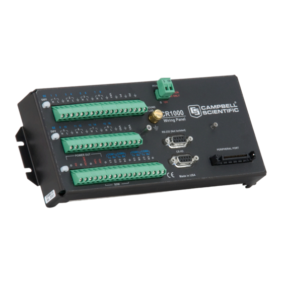
Page 57: Wiring Panel - Overview
In the following figure, the CR1000 wiring panel is illustrated. The wiring panel is the interface to most CR1000 functions so studying it is a good way to get acquainted with the CR1000. Functions of the terminals are broken down into the following categories. -
Page 58: Figure 1: Wiring Panel
Section 5. Overview FIGURE 16: Wiring Panel CR1000 Wiring Panel Terminal Definitions DIFF ┌ 1 ┐ ┌ 2 ┐ ┌ 3 ┐ ┌ 4 ┐ ┌ 5 ┐ ┌ 6 ┐ ┌ 7 ┐ ┌ 8 ┐ Analog Input Single-ended ... - Page 59 Section 5. Overview Switch closure High frequency Low-level Vac Digital I/O Control Status ...
-
Page 60: Switched Voltage Output - Overview
C terminals are selectable as binary inputs, control outputs, or communication ports. See Measurements — Overview for a summary of measurement (p. 65) functions. Other functions include device-driven interrupts, asynchronous communications and SDI-12 communications. Table CR1000 Terminal summarizes available options. Definitions (p. 58) Figure Control and Monitoring with C Terminals illustrates a simple (p. -
Page 61: Power Terminals
CR1000 as a power supply for sensors and peripheral devices. The CR1000 can be used as a power source for sensors and peripherals. The following voltages are available: 12V terminals: unregulated nominal 12 Vdc. This supply closely tracks •... -
Page 62: Communication Ports - Overview
• CPI Port and CDM Devices — Overview (p. 64) • PakBus — Overview (p. 79) • RS-232 and TTL (p. 403) The CR1000 is equipped with hardware ports that allow communication with other devices and networks, such as: • Smart sensors • •... -
Page 63: Cs I/O Port
Note RS-232 ports are not isolated (p. 528). 5.1.1.4.3 Peripheral Port Provided for connection of some Campbell Scientific CF memory card modules and IP network link hardware. See the appendices TCP/IP Links — List (p. 596) and Data Storage Devices — List See Memory Card (CRD: Drive) —... -
Page 64: Ports
• CPI Port and CDM Devices — Details (p. 478) CPI is a new proprietary protocol that supports an expanding line of Campbell Scientific CDM modules. CDM modules are higher-speed input- and output-expansion peripherals. CPI ports also enable networking between compatible Campbell Scientific dataloggers. -
Page 65: Measurements - Overview
• Time Keeping — Details (p. 319) Measurement of time is an essential function of the CR1000. Time measurement with the on-board clock enables the CR1000 to attach time stamps to data, measure the interval between events, and time the initiation of control functions. -
Page 66: Analog Measurements - Overview
Analog sensors output a continuous voltage or current signal that varies with the phenomena measured. Sensors compatible with the CR1000 output a voltage. The CR1000 can also measure analog current output when the current is converted to voltage by using a resistive shunt. -
Page 67: Figure 18: Analog Sensor Wired To Single-Ended Channel #1
Section 5. Overview unless the same voltage-excitation terminal is enabled during the unrelated measurements. Measured voltage is less than 200 mV. • FIGURE 18: Analog Sensor Wired to Single-Ended Channel #1 FIGURE 19: Analog Sensor Wired to Differential Channel #1... -
Page 68: Single-Ended Measurements - Overview
Rapid sampling is required. Single-ended measurement time is about half that of differential measurement time. • Sensor is not designed for differential measurements. Many Campbell Scientific sensors are not designed for differential measurement, but the draw backs of a single-ended measurement are usually mitigated by large... -
Page 69: Differential Measurements - Overview
If the measuring junction of a thermocouple used to measure soil temperature is not insulated, and the potential of earth ground is greater at the sensor than at the point where the CR1000 is grounded, a measurement error will result. For example, if the difference in grounds is 1 mV, with a copper-constantan thermocouple, the error will be approximately 25 °C. -
Page 70: Resistance Measurements - Overview
PT1000 (p. 266). resistors into a resistor bridge. Sensor manufacturers consider many criteria when deciding what type of resistive bridge to use for their sensors. The CR1000 can measure most bridge circuit configurations. 5.2.2.3.1 Voltage Excitation Bridge resistance is determined by measuring the difference between a known voltage applied to the excitation (input) arm of a resistor bridge and the voltage measured on the output arm. -
Page 71: Strain Measurements - Overview
The output signal generated by a pulse sensor is a series of voltage waves. The sensor couples its output signal to the measured phenomenon by modulating wave frequency. The CR1000 detects the state transition as each wave varies between voltage extremes (high-to-low or low-to-high). Measurements are processed and presented as counts, frequency, or timing data. -
Page 72: Pulses Measured
PeriodAverage() instruction. See Period Averaging — Overview (p. 74). 5.2.3.1 Pulses Measured The CR1000 measures three types of pulse outputs, which are illustrated in the figure Pulse Sensor Output Signal Types (p. 72). FIGURE 22: Pulse Sensor Output Signal Types 5.2.3.2 Pulse Input Channels... -
Page 73: Pulse Sensor Wiring
Connect the other wire to a P terminal. Sometimes the sensor will require power from the CR1000, so there may be two added wires — one of which will be power ground. Connect power ground to a G terminal. Do not confuse the pulse wire with the positive power wire, or damage to the sensor or CR1000 may result. -
Page 74: Period Averaging - Overview
Vibrating wire sensors are the sensor of choice in many environmental and industrial applications that need sensors that will be stable over very long periods, such as years or even decades. The CR1000 can measure these sensors either directly or through interface modules. -
Page 75: Reading Smart Sensors - Overview
(p. 404) • Serial I/O: SDI-12 Sensor Support — Programming Resource (p. 248) SDI-12 is a smart-sensor protocol that uses one input port on the CR1000 and is powered by 12 Vdc. Refer to the chart CR1000 Terminal Definitions which (p. -
Page 76: Overview
Section 5. Overview 5.2.6.2 RS-232 — Overview The CR1000 has 6 ports available for RS-232 input as shown in figure Terminals Configurable for RS-232 Input (p. 76). As indicated in figure Use of RS-232 and Digital I/O when Reading RS-232... -
Page 77: Field Calibration - Overview
Adjusting sensor output directly is preferred, but not always possible or practical. By adding FieldCal() or FieldCalStrain() instructions to the CR1000 CRBasic program, measurements of a linear sensor can be adjusted by modifying the programmed multiplier and offset applied to the measurement without modifying or recompiling the CRBasic program. -
Page 78: Data File Formats In Cr1000 Memory
Data stored on a SC115 Campbell Scientific mass storage device can be retrieved via a comms link to the CR1000 if the device remains on the CS I/O port. Data can also be retrieved by removing the device, connecting it to a PC, and copying off files using Windows File Explorer. -
Page 79: Comms
CR1000 often erases all data. Data stored on a memory card are collected to a PC through a comms link with the CR1000 or by removing the card and collecting it directly using a third-party adapter on a PC. 5.3.4.1 Comms... -
Page 80: Alternate Comms Protocols - Overview
Campbell Scientific datalogger. PakBus supports automatic route detection and selection. • Short distance networks — with no extra hardware, a CR1000 can talk to another CR1000 over distances up to 30 feet by connecting transmit, receive and ground wires between the dataloggers. -
Page 81: Modbus - Overview
Modbus driver of the master and / or the slaves. The CR1000 supports RTU and ASCII communication modes on RS-232 and RS485 connections. It exclusively uses the TCP mode on IP connections. -
Page 82: Comms Hardware - Overview
• • 5.3.7 Comms Hardware — Overview The CR1000 can accommodate, in one way or another, nearly all comms options. Campbell Scientific specializes in RS-232, USB, RS-485, short haul (twisted pairs), Wi-Fi, radio (single frequency and spread spectrum), land-line telephone, cell phone / IP modem, satellite, ethernet/internet, and sneaker net (external memory). -
Page 83: Character Set
Character, press Enter, then press ▲, ▼, ◄, ► to scroll to the desired character in the list that is presented, then press Enter. 5.3.8.2 Custom Menus — Overview CRBasic programming in the CR1000 facilitates creation of custom menus for the CR1000KD Keyboard/Display. Figure Custom Menu Example shows windows from a simple custom menu (p. -
Page 84: Measurement And Control Peripherals - Overview
Vx excitation terminals. SDM Devices Serial Device for Measurement expand the input and output capacity of the CR1000. These devices connect to the CR1000 through terminals C1, C2, and C3. CDM Devices Campbell Distributed Modules measurement and control modules that use the high speed CAN Peripheral Interface (CPI) bus technology. -
Page 85: Power Supplies - Overview
Section 5. Overview Power Supplies — Overview The CR1000 is powered by a nominal 12 Vdc source. Acceptable power range is 9.6 to 16 Vdc.External power connects through the green POWER IN connector on the face of the CR1000. The positive power lead connects to 12V. The negative lead connects to G. -
Page 86: Security - Overview
A program is created on a PC and sent to the CR1000. The CR1000 can store a number of programs in memory, but only one program is active at a given time. Two Campbell Scientific software applications, Short Cut and CRBasic Editor, are used to create CR1000 programs. -
Page 87: Maintenance - Overview
5.9.2 Protection from Voltage Transients — Overview The CR1000 must be grounded to minimize the risk of damage by voltage transients associated with power surges and lightning-induced transients. Earth grounding is required to form a complete circuit for voltage clamping devices... -
Page 88: Factory Calibration - Overview
Dispose of spent lithium batteries properly. The CR1000 contains a lithium battery that operates the clock and powers SRAM when the CR1000 is not externally powered. Voltage of the battery is monitored from the CR1000 Status table (LithiumBattery . -
Page 89: Plc Control - Overview
Section 5. Overview Datalogger support software handles communication between a computer or device and the CR1000. A wide array of software are available, but the following are the most commonly used: • Short Cut Program Generator for Windows (SCWin) — Generates... - Page 90 C terminals can be set low (0 (p. 409) Vdc) or high (5 Vdc) using PortSet() or WriteIO() instructions. Control modules are available to expand and augment CR1000 control capacity. On / off and proportional control modules are available. See appendix PLC Control Modules — List (p.
-
Page 91: Auto Self-Calibration - Overview
• Factory Calibration or Repair Procedure (p. 486) The CR1000 auto self-calibrates to compensate for changes caused by changing operating temperatures and aging. Disable auto self-calibration when it interferes with execution of very fast programs and less accuracy can be tolerated. - Page 92 Section 5. Overview • Main Memory Battery backed OS variables CRBasic compiled program binary structure (490 KB maximum) CRBasic variables Data memory Communication memory USR: drive — User allocated — FAT32 RAM drive — Photographic images (see Cameras — List (p.
-
Page 93: Specifications
Specifications CR1000 specifications are valid from ─25° to 50°C in non-condensing environments unless otherwise specified. Recalibration is recommended every three years. Critical specifications and system configurations should be confirmed with a Campbell Scientific sales engineer before purchase. PROGRAM EXECUTION RATE PERIOD AVERAGE DIGITAL I/O PORTS (C 1–8) -
Page 95: Installation
(p. 95) Campbell Scientific designed for housing the CR1000. This style of enclosure is classified as NEMA 4X (watertight, dust-tight, corrosion-resistant, indoor and outdoor use). Enclosures have back plates to which are mounted the CR1000 datalogger and associated peripherals. -
Page 96: Power Supplies - Details
7.2.1 CR1000 Power Requirement The CR1000 operates with power from 9.6 to 16 Vdc applied at the POWER IN terminals of the green connector on the face of the wiring panel. -
Page 97: Calculating Power Consumption
(ampere-hours) by the average system current drain (amperes). The CR1000 typically has a quiescent current drain of 0.5 mA (with display off) 0.6 mA with a 1 Hz sample rate, and >10 mA with a 100 Hz scan rate. When the CR1000KD Keyboard/Display is active, an additional 7 mA is added to the current drain while enabling the backlight for the display adds 100 mA. -
Page 98: Uninterruptable Power Supply (Ups)
7.2.5 External Power Supply Installation When connecting external power to the CR1000, remove the green POWER IN connector from the CR1000 face. Insert the positive 12 Vdc lead into the green connector, then insert the negative lead. Re-seat the green connector into the CR1000. -
Page 99: Esd Protection
The primary devices for protection against ESD are gas-discharge tubes (GDT). All critical inputs and outputs on the CR1000 are protected with GDTs or transient voltage suppression diodes. GDTs fire at 150 V to allow current to be diverted to the earth ground lug. -
Page 100: Lightning Protection
The system employs a lightening rod, metal mast, heavy-gage ground wire, and ground rod to direct damaging current away from the CR1000. This system, however, not infallible. Figure Lightning Protection Scheme is a drawing (p. -
Page 101: Single-Ended Measurement Reference
FIGURE 31: Lightning Protection Scheme 7.3.2 Single-Ended Measurement Reference Low-level, single-ended voltage measurements (<200 mV) are sensitive to ground potential fluctuation due to changing return currents from 12V, SW12, 5V, and C1 – C8 terminals. The CR1000 grounding scheme is designed to minimize... -
Page 102: Ground Potential Differences
1 mV greater at the sensor than at the point where the CR1000 is grounded, the measured voltage is 1 mV greater than the thermocouple output. With a copper-constantan thermocouple, 1 mV equates to approximately 25 °C measurement error. -
Page 103: Ground Looping In Ionic Measurements
(soil moisture) sensor, a ground loop arises because soil and water provide an alternate path for the excitation to return to CR1000 ground. This example is modeled in the diagram Model of a Ground Loop with a Resistive... -
Page 104: Protection From Moisture - Details
When humidity levels reach the dew point, condensation occurs and damage to CR1000 electronics can result. Effective humidity control is the responsibility of the user. The CR1000 module is protected by a packet of silica gel desiccant, which is installed at the factory. This packet is replaced whenever the CR1000 is repaired at Campbell Scientific. -
Page 105: Tools - Setup
DevConfig Help guides you through connection and use. The simplest connection is to connect a serial cable from the computer COM port or USB port to the RS-232 port on the CR1000 as shown in figure Connect Power and Comms. -
Page 106: Network Planner - Setup Tools
Section 7. Installation FIGURE 33: Device Configuration Utility (DevConfig) 7.5.1.2 Network Planner — Setup Tools Network Planner is a drag-and-drop application used in designing PakBus datalogger networks. You interact with Network Planner through a drawing canvas upon which are placed PC and datalogger nodes. Links representing various comms options are drawn between nodes. -
Page 107: Overview - Network Planner
Section 7. Installation FIGURE 34: Network Planner Setup 7.5.1.2.1 Overview — Network Planner Network Planner allows you to Create a graphical representation of a network, as shown in figure • Network Planner Setup (p. 107), • Determine settings for devices and LoggerNet, and Program devices and LoggerNet with new settings. -
Page 108: Basics - Network Planner
Section 7. Installation • It does not generate datalogger programs. It does not understand distances or topography; that is, it does not warn • when broadcast distances are exceeded, nor does it identify obstacles to radio transmission. For more detailed information on Network Planner, please consult the LoggerNet manual, which is available at www.campbellsci.com. -
Page 109: Info Tables And Settings - Setup Tools
(p. 494) Info tables and settings contain fields, settings, and information essential to setup, programming, and debugging of many advanced CR1000 systems. Info tables and settings are numerous. Note the following: All info tables and settings, except a handful, are accessible through a •... -
Page 110: Crbasic Program - Setup Tools
Section 7. Installation Note Communication and processor bandwidth are consumed when generating the Status and and other information tables. If the CR1000 is very tight on processing time, as may occur in very long or complex operations, retrieving these tables repeatedly may cause skipped scans 496). -
Page 111: Default.cr1 File
Powerup.ini has a different, limited programming language. 7.5.1.5.1 Default.cr1 File A file named default.cr1 can be stored on the CR1000 CPU: drive. At power up, the CR1000 loads default.cr1 if no other program takes priority (see Executable . Default.cr1 can be edited to preserve critical File Run Priorities (p. - Page 112 5. If there is no default.cr1 file or if that file cannot be compiled, the datalogger will not run any program. The CR1000 will now allow a SlowSequence statement to take the place of the BeginProg statement. This feature allows the specified file to act both as an include file and as the default program.
-
Page 113: Figure 35: "Include" File Settings With Devconfig
Section 7. Installation FIGURE 35: "Include" File Settings With DevConfig FIGURE 36: "Include" File Settings With PakBusGraph... -
Page 114: Using An "Include" File
Including the SlowSequence instruction as the first statement is required, followed by any other code. '2. Send the 'include' file to the CPU: drive of the CR1000 using the File Control menu of the datalogger support software Be sure to de-select the Run Now and Run On Power-up options that are presented by the software when sending the file. -
Page 115: Executable File Run Priorities
CR1000 will attempt to run the program named default.cr1 on its CPU: drive. 6. If there is no default.cr1 file or it cannot be compiled, the CR1000 will not automatically run any program. 7.5.2 Setup Tasks Following are a few common configuration actions: •... -
Page 116: Operating System (Os) - Details
DevConfig Help. OS version is displayed in the following location: Deployment tab → Datalogger tab → OS Version text box Update the OS on the CR1000 as directed in DevConfig Help. The current version of the OS is found at www.campbellsci.com/downloads. OS updates are free of charge. -
Page 117: Os Update With Devconfig Send Os Tab
Follow the on-screen OS Download Instructions Pros/Cons This is a good way to recover a CR1000 that has gone into an unresponsive state. Often, an operating system can be loaded even if you are unable to communicate with the CR1000 through other means. -
Page 118: Os Update With File Control
SRAM memory allocated for data storage) 5. Collect files from the USR: drive (if applicable) 6. Delete the USR: drive (if applicable) 7. Send the new .obj OS file to the CR1000 8. Restart the previous program (default.CR1 will be running after OS compiles) Pros/Cons... -
Page 119: Program Send Command Locations
CRBasic Editor and specify new run options. Pros/Cons This is the best way to load a new operating system on the CR1000 and have its settings retained (most of the time). This means that you will still be able to... -
Page 120: Os Update With External Memory And Powerup.ini File
USR drive you will probably need to remove it as well. Loading an operating system through this method will do the following: 1. Preserve all CR1000 settings 2. Delete all data in final storage 3. Stop current program (Stop and deletes data) and clears run options 4. -
Page 121: Factory Defaults - Installation
In DevConfig, clicking the Factory Defaults button at the base of the Settings Editor tab sends a command to the CR1000 to revert to its factory default settings. The reverted values will not take effect until the changes have been applied. -
Page 122: Crbasic Programming - Details
Section 7. Installation FIGURE 37: Summary of CR1000 Configuration CRBasic Programming — Details Related Topics: • CRBasic Programming — Overview (p. 85) • CRBasic Programming — Details (p. 122) • Programming Resource Library (p. 174) • CRBasic Editor Help Programs are created with either Short Cut... -
Page 123: Crbasic Program Structure
Alias Assign aliases to variables. Optional. Assign engineering units to variables. Units are Units not active code. The CR1000 makes no use of units nor checks unit accuracy. DataTable Define stored-data tables. Sample() Process or store trigger: set triggers when data should •... - Page 124 Section 7. Installation CRBasic Program Structure 'Declarations 'Define Constants Const RevDiff = 1 Const Del = 0 'default Const Integ = 250 Declare constants Const Mult = 1 Const Offset = 0 'Define public variables Public RefTemp Public TC(6) 'Define Units Declare public variables, Declarations Units...
-
Page 125: Writing And Editing Programs
The program can then be edited further using CRBasic Program Editor. 7.6.2.2 CRBasic Editor CR1000 application programs are written in a variation of BASIC (Beginner's All-purpose Symbolic Instruction Code) computer language, CRBasic (Campbell... -
Page 126: Inserting Comments Into Program
('). Comments can be entered either as independent lines or following CR1000 code. When the CR1000 compiler sees a single quote ('), it ignores the rest of the line. -
Page 127: Conserving Program Memory
Section 7. Installation Inserting Comments 'This program example demonstrates the insertion of comments into a program. Comments are 'placed in two places: to occupy single lines, such as this explanation does, or to be 'placed after a statement. 'Declaration of variables starts here. Public Start(6) 'Declare the start time array... -
Page 128: Multiple Statements On One Line
Section 7. Installation 7.6.3.1.1 Multiple Statements on One Line Multiple short statements can be placed on a single text line if they are separated by a colon (:). This is a convenient feature in some programs. However, in general, programs that confine text lines to single statements are easier for humans to read. -
Page 129: Declaring Variables
Section 7. Installation Alias • StationName • The table Rules for Names lists declaration names and allowed lengths. (p. 162) See Predefined Constants for other naming limitations. (p. 141) 7.6.3.3 Declaring Variables A variable is a packet of memory that is given an alphanumeric name. Measurements and processing results pass through variables during program execution. -
Page 130: Declaring Data Types
Section 7. Installation 7.6.3.3.1 Declaring Data Types Variables and data values stored in final memory can be configured with various data types to optimize program execution and memory usage. The declaration of variables with the Dim or Public instructions allows an optional type descriptor As that specifies the data type. - Page 131 ASCII string Maximu Maximum length is limited only by begins with a non-numeric, available CR1000 memory. As a special the FLOAT will be NAN. If limited case, a string can be declared as String * 1. the string contains multiple...
- Page 132 Section 7. Installation Data Types in Final-Storage Memory Word Name Argument Description Size Notes Resolution / Range (Bytes) Use to store count data in the range of ±2,147,483,648 Speed: integer math is faster than floating point math. Resolution: 32 bits. Compare to 24 bits in IEEE4.
-
Page 133: Data Type Declarations
ASCII string String Maximu Maximum length is limited only by string begins with a non-numeric, available CR1000 memory. As a the FLOAT will be NAN. If the limited special case, a string can be declared as string contains multiple numeric only to String * 1. -
Page 134: Dimensioning Numeric Variables
Section 7. Installation 'Boolean Variable Examples Public Switches(8) As Boolean Public FLAGS(16) As Boolean 'String Variable Example Public FirstName As String * 16 'allows a string up to 16 characters long DataTable(TableName,True,-1) 'FP2 Data Storage Example Sample(1,Z,FP2) 'IEEE4 / Float Data Storage Example Sample(1,X,IEEE4) 'UINT2 Data Storage Example Sample(1,PosCounter,UINT2) -
Page 135: Dimensioning String Variables
Using Variable Array Dimension Indices (p. 135)) Long variables is recommended. Doing so allows for more efficient use of CR1000 resources. Using Variable Array Dimension Indices 'This program example demonstrates the use of dimension indices in arrays. The variable 'VariableName is declared with three dimensions with 4 in each index. -
Page 136: Using Variable Pointers
'and the use of strings to report flag status. To run the demonstration, send this program 'to the CR1000, then toggle variables Flag(1) and Flag(2) to true or false to see how the 'program logic sets the words "High" or "Low" in variables FlagReport(1) and FlagReport(2). -
Page 137: Declaring Arrays
Section 7. Installation When a Function() function returns a pointer, apply the ! operator to the function call, as shown in the following example: Function ConstrainFunc(Value As Long,Low As Long,High As Long) As Long !Value < !Low Then Return ElseIf !Value >... -
Page 138: Advanced Array Declaration
Section 7. Installation Using a Variable Array in Calculations 'This program example demonstrates the use of a variable array to reduce code. In this 'example, two variable arrays are used to convert four temperature measurements from 'degree C to degrees F. Public TempC(4) Public... -
Page 139: Declaring Local And Global Variables
Section 7. Installation • scale an array dimension perform a mathematical or logical operation for each element in a • dimension using scalar or similarly located elements in different arrays and dimensions Here are some syntax rules and behaviors. Given the array, Array(A,B,C): The () pair must always be present, i.e., reference the array as Array() or •... -
Page 140: Declaring Constants
Section 7. Installation Initializing Variables 'This program example demonstrates how variables can be declared as specific data types. 'Variables not declared as a specific data type default to data type Float. Also 'demonstrated is the loading of values into variables that are being declared. Public As Long 'Declaring a single variable As Long and loading the value of 1. -
Page 141: Predefined Constants
CRBasic program development. The compiler will catch the use of any reserved words. Following are listed predefined constants that are assigned a value: LoggerType = 1000 (as in CR1000) • These may be useful in programming. -
Page 142: Numerical Formats
Scientific notation, binary, and hexadecimal formats can also be used, as shown in the table Formats for Entering Numbers in CRBasic (p. 142). Only standard, base-10 notation is supported by Campbell Scientific hardware and software displays. Formats for Entering Numbers in CRBasic... -
Page 143: Multi-Statement Declarations
Section 7. Installation Load binary information into a variable 'This program example demonstrates how binary data are loaded into a variable. The binary 'format (1 = high, 0 = low) is useful when loading the status of multiple flags 'or ports into a single variable. For example, storing the binary number &B11100000 'preserves the status of flags 8 through 1: flags 1 to 5 are low, 6 to 8 are high. -
Page 144: Declaring Data Tables
The trigger that initiates data storage is tripped either by the CR1000 clock, or by an event, such as a high temperature. The maximum number of data tables is 253 (prior to OS 28, the limit was 30 data tables), but the maximum can vary with other programming considerations. -
Page 145: Typical Data Table
Each line consists of one or more fields. The first four lines constitute the file header. Subsequent lines contain data. Note Discrete data files (ASCII or binary) can also be written to a CR1000 memory drive using the TableFile() instruction. -
Page 146: Declaration And Use Of A Data Table
Declaration and Use of a Data Table Units are strictly for (p. 146). documentation. The CR1000 does not make use of declared units, nor does it check their accuracy. The fourth line of the header reports abbreviations of the data process used to produce the field of data. - Page 147 If –1 is entered, memory for the table is allocated automatically at the time the program compiles. Automatic allocation is preferred in most applications since the CR1000 sizes all tables such that they fill (and...
- Page 148 Scan() / NextScan interval. Sometimes, usually because of a timing issue, program logic prevents a record from being written. If a record is not written, the CR1000 recognizes the omission as a "lapse" and increments the SkippedRecord counter in the Status table.
-
Page 149: Datainterval() Lapse Parameter Options
TableFile() instruction with Option 64. If a program is planned to experience multiple lapses, and if comms bandwidth is not a consideration, the Lapses parameter should be set to 0 to ensure the CR1000 allocates adequate memory for each data table. - Page 150 Section 7. Installation Note Array-based dataloggers, such as CR10X and CR23X, use open intervals exclusively. Data Output Processing Instructions Data-storage processing instructions (aka, "output processing" instructions) determine what data are stored in a data table. When a data table is called in the CRBasic program, data-storage processing instructions process variables holding current inputs or calculations.
-
Page 151: Declaring Subroutines
Section 7. Installation Use of the Disable Variable 'This program example demonstrates the use of the 'disable' variable, or DisableVar, which 'is a parameter in many output processing instructions. Use of the 'disable' variable 'allows source data to be selectively included in averages, maxima, minima, etc. If the ''disable' variable equals -1, or true, data are not included;... -
Page 152: Declaring Subroutines
Note A particular subroutine can be called by multiple program sequences simultaneously. To preserve measurement and processing integrity, the CR1000 queues calls on the subroutine, allowing only one call to be processed at a time in the order calls are received. This may cause unexpected pauses in the conflicting program sequences. -
Page 153: Execution And Task Priority
These tasks are executed in either pipeline or sequential mode. When in pipeline mode, tasks run more or less in parallel. When in sequential mode, tasks run more or less in sequence. When a program is compiled, the CR1000 evaluates the program and automatically determines which mode to use. Using the PipelineMode or SequentialMode instruction at the beginning of the program will force the program into one mode or the other. -
Page 154: Pipeline Mode
In this way, all tasks are given equal processing time by the CR1000. All tasks are given the same general priority. However, when a conflict arises between tasks, program execution adheres to the following priority schedule: 1. -
Page 155: Sequential Mode
CRBasic program to make sure that the initializing sequence has completed before the dependent task can proceed. This can be done with a simple variable or even a delay, but understand that the CR1000 operating system will not do this handshaking between independent tasks. -
Page 156: Execution Timing
EndProg 7.6.3.13.1 Scan() / NextScan Simple CR1000 programs are often built entirely within a single Scan() / NextScan structure, with only variable and data-table declarations outside the scan. Scan() / NextScan creates an infinite loop; each periodic pass through the loop is synchronized to the CR1000 clock. -
Page 157: Slowsequence / Endsequence
Section 7. Installation BeginProg / Scan() / NextScan / EndProg Syntax 'This program example demonstrates the use of BeginProg/EndProg and Scan()/NextScan syntax. Public PanelTemp_ DataTable(PanelTempData,True,-1) DataInterval(0,1,Min,10) Sample(1,PanelTemp_,FP2) EndTable BeginProg <<<<<<<BeginProg Scan(1,Sec,3,0) <<<<<<< Scan PanelTemp(PanelTemp_,250) CallTable PanelTempData NextScan <<<<<<< NextScan EndProg <<<<<<<EndProg Scan() determines how frequently instructions in the program are executed, as shown in the following CRBasic code snip:... -
Page 158: Subscan() / Nextsubscan
For example, a weather-measurement program may scan once per second, but program execution may only occupy 250 ms, leaving 75% of available scan time unused. The CR1000 can make efficient use of this interstitial-scan time to optimize program execution and communication control. - Page 159 Any processing will be time sliced with (p. 159). processing from other sequences. Every time the program encounters WaitDigTrig(), it will stop and wait to be triggered. Note WaitDigTrig() can be used to program a CR1000 to control another CR1000.
-
Page 160: Programming Instructions
Measurement and Data Storage Processing CRBasic instructions have been created for making measurements and storing data. Measurement instructions set up CR1000 hardware to make measurements and store results in variables. Data storage instructions process measurements into averages, maxima, minima, standard deviation, FFT, etc. -
Page 161: Argument Types
CRBasic example Measurement Instruction Syntax (p. 161). Measurement Instruction Syntax 'This program example demonstrates the use of a single measurement instruction. In this 'case, the program measures the temperature of the CR1000 wiring panel. Public RefTemp 'Declare variable to receive instruction BeginProg Scan(1,Sec,3,0) PanelTemp(RefTemp, 250) '<<<<<<Instruction to make measurement... -
Page 162: Expressions In Arguments
Section 7. Installation Rules for Names Maximum Length Name (number of Allowed characters Category characters) Variable or array Constant Letters A to Z, a to z, _ (underscore), Units and numbers 0 to 9. Names must start with a letter or underscore. CRBasic is not case sensitive. -
Page 163: Programming Expression Types
(p. 491) • TABLE: Data Types in Variable Memory (p. 130) All arithmetic in the CR1000, and all declared variables, are single precision IEEE four-byte floating point. A few operations are performed as double precision. These are AddPrecise(), Average(), AvgRun(), AvgSpa(), CovSpa(), MovePrecise(), RMSSpa(), StdDev(), StdDevSpa(), Totalize(), and TotRun(). -
Page 164: Arithmetic Operations
Section 7. Installation • Floating-point arithmetic does not perfectly mimic true arithmetic. Avoid use of equality in conditional statements. Use >= and <= instead. • For example, use If X >= Y then do rather than If X = Y then do. •... -
Page 165: Conversion Of Float / Long To Boolean
Section 7. Installation Conversion of FLOAT / LONG to Boolean 'This program example demonstrates conversion of Float and Long data types to Boolean 'data type. Public As Float Public As Float Public As Long Public As Boolean Public As Boolean Public As Boolean BeginProg... -
Page 166: Logical Expressions
EndProg Constants Conversion Constants are not declared with a data type, so the CR1000 assigns the data type as needed. If a constant (either entered as a number or declared with CONST) can be expressed correctly as an integer, the compiler will use the type that is most efficient in each expression. -
Page 167: Binary Conditions Of True And False
TRUE is predefined as -1 in the CR1000 system memory. By entering = TRUE, a literal comparison is done. So, to be absolutely certain a function is true, it must be set to TRUE or -1. -
Page 168: Logical Expression Examples
Sets the variable Y to 0 if the expression "X >= 5" is true, i.e. if X is greater than or equal to 5. The CR1000 evaluates the expression (X >= 5) and registers in system memory a -1 if the expression is true, or a 0 if the expression is false. -
Page 169: String Expressions
Section 7. Installation Logical Expression Examples The NOT operator complements every bit in the word. A Boolean can be FALSE (0 or all bits set to 0) or TRUE (-1 or all bits set to 1). Complementing a Boolean turns TRUE to FALSE (all bits complemented to 0). Example Program '(a AND b) = (26 AND 26) = (&b11010 AND &b11010) = '&b11010. -
Page 170: Programming Access To Data Tables
Section 7. Installation 'Program BeginProg Scan(1,Sec,0,0) 'Assign strings to String variables Word(1) = "Good" Word(2) = "morning" Word(3) = "Dave" Word(4) = "I'm" Word(5) = "sorry" Word(6) = "afraid" Word(7) = "I" Word(8) = "can't" Word(9) = "do" Word(10) = "that" Word(11) = "... -
Page 171: Data Process Abbreviations
Section 7. Installation Prc is the abbreviation of the name of the data process used. See table • Data Process Abbreviations for a complete list of these (p. 171) abbreviations. This is not needed for values from Status or Public tables. Fieldname Index is the array element number in fields that are arrays •... -
Page 172: Programming To Use Signatures
Section 7. Installation where wderr is a declared variable, status is the table name, and watchdogerrors is the keyword for the watchdog error field. Seven special variable names are used to access information about a table. • EventCount EventEnd • Output •... -
Page 173: Sending Crbasic Programs
Function/EndFunction 7.6.4 Sending CRBasic Programs The CR1000 requires that a CRBasic program file be sent to its memory to direct measurement, processing, and data storage operations. The program file can have the extension cr1 or .dld and can be compressed using the GZip algorithm before sending it to the CR1000. -
Page 174: Programming Resource Library
Reset memory and set CRBasic program attributes to Run Always FIGURE 39: CRBasic Editor Program Send File Control window Programming Resource Library This library of notes and CRBasic code addresses a narrow selection of CR1000 applications. 7.7.1 Advanced Programming Techniques 7.7.1.1 Capturing Events... -
Page 175: Conditional Output
Section 7. Installation BeginProg / Scan / NextScan / EndProg Syntax 'This program example demonstrates detection and recording of an event. An event has a 'beginning and an end. This program records an event as occurring at the end of the event. 'The event recorded is the transition of a delta temperature above 3 degrees. -
Page 176: Groundwater Pump Test
Section 7. Installation Conditional Output 'This program example demonstrates the conditional writing of data to a data table. 'also demonstrates use of StationName() and Units instructions. 'Declare Station Name (saved to Status table) StationName(Delta_Temp_Station) 'Declare Variables Public PTemp_C, AirTemp_C, DeltaT_C 'Declare Units Units PTemp_C = deg C... -
Page 177: Groundwater Pump Test
Section 7. Installation Groundwater Pump Test 'This program example demonstrates the use of multiple scans in a program by running a 'groundwater pump test. Note that Scan() time units of Sec have been changed to mSec for 'this demonstration to allow the program to run its course in a short time. To use this 'program for an actual pump test, change the Scan() instruction mSec arguments to Sec. - Page 178 Section 7. Installation 'Minute 10 to 30 of test: 30-second data-output interval Scan(30,mSec,0,40)'There are 40 30-second scans in 20 minutes ScanCounter(2) = ScanCounter(2) + 1 'Included to show passes through this scan Battery(Batt_volt) PanelTemp(PTemp,250) Call MeasureLevel 'Call Output Tables CallTable LogTable NextScan 'Minute 30 to 100 of test: 60-second data-output interval...
-
Page 179: Miscellaneous Features
Miscellaneous Program Features 'This program example demonstrates the use of a single measurement instruction. In this 'case, the program measures the temperature of the CR1000 wiring panel. Public RefTemp 'Declare variable to receive instruction BeginProg... - Page 180 Section 7. Installation 'Optional – Declare a Station Name into a location in the Status table. StationName(CR1000_on_desk) 'Optional -- Declare units. Units are not used in programming, but only appear in the 'data file header. Units Batt_Volt = Volts Units PTemp = deg C Units AirTemp = deg C...
-
Page 181: Pulsecountreset Instruction
'after EventCount just needs to be included. HowMany = Event.EventCount(1,1) 'Call Data Tables CallTable(OneMin) CallTable(Event) NextScan EndProg 7.7.1.5 PulseCountReset Instruction PulseCountReset is used in rare instances to force the reset or zeroing of CR1000 pulse accumulators. See Measurements — Overview (p. 65). -
Page 182: Scaling Array
Section 7. Installation PulseCountReset is needed in applications wherein two separate PulseCount() instructions in separate scans measure the same pulse input terminal. While the compiler does not allow multiple PulseCount() instructions in the same scan to measure the same terminal, multiple scans using the same terminal are allowed. PulseCount() information is not maintained globally, but for each individual instruction occurrence. -
Page 183: Signatures: Example Programs
Section 7. Installation Scan(5,Sec,1,0) 'Measure reference temperature PanelTemp(PTemp_C,250) 'Measure three thermocouples and scale each. Scaling factors from the scaling array 'are applied to each measurement because the syntax uses an argument of 3 in the Reps 'parameter of the TCDiff() instruction and scaling variable arrays as arguments in the 'Multiplier and Offset parameters. -
Page 184: Use Of Multiple Scans
Section 7. Installation Program Signatures 'This program example demonstrates how to request the program text signature (ProgSig = Status.ProgSignature), and the 'binary run-time signature (RunSig = Status.RunSignature). It also calculates two 'executable code segment signatures (ExeSig(1), ExeSig(2)) 'Define Public Variables Public RunSig, ProgSig, ExeSig(2),x,y 'Define Data Table... -
Page 185: Data Input: Loading Large Data Sets
'End executable section of program 7.7.2 Data Input: Loading Large Data Sets Large data sets like look-up tables or tag numbers, can be loaded in the CR1000 for use by the CRBasic program. Do this by using the Data, DataLong, and Read instructions, as demonstrated in CRBasic example Loading Large Data Sets (p. -
Page 186: Data Input: Array-Assigned Expression
Thousands of values can be loaded in this way. 'Declare Float and Long variables. Can also be declared as Dim. Public DataSetFloat(10) As Float Public DataSetLong(10) As Long 'Write data set to CR1000 memory Data 1.1,2.2,3.3,4.4,5.5 Data -1.1,-2.2,-3.3,-4.4,-5.5 DataLong 1,2,3,4,5 DataLong -1,-2,-3,-4,-5... - Page 187 Section 7. Installation • Mathematical Logical • Examples include: Process a variable array without use of For/Next • Create boolean arrays based on comparisons with another array or a • scalar variable Copy a dimension to a new location • Perform logical operations for each element in a dimension using scalar •...
-
Page 188: Array Assigned Expression: Sum Columns And Rows
Section 7. Installation • If indices are not specified, or none have been preceded with a minus sign, the least significant dimension of the array is assumed. The offset into the dimension being accessed is given by (a,b,c). • • If the array is referenced as array(), the starting point is array(1,1,1) and the least significant dimension is accessed. -
Page 189: Array Assigned Expression: Comparison Boolean Evaluation
Section 7. Installation BeginProg Scan (1,Sec,0,0) i = 1 To 2 'For each column of the source array A(), copy the column into a row of the 'destination array At() At(i,-1)() = A(-1,i)() Next NextScan EndProg Array Assigned Expression: Comparison / Boolean Evaluation 'Example: Comparison / Boolean Evaluation 'Element-wise comparisons is performed through scalar expansion or by comparing each 'element in one array to a similarly located element in another array to generate a... -
Page 190: Data Output: Calculating Running Average
Section 7. Installation Array Assigned Expression: Fill Array Dimension 'Example: Fill Array Dimension Public A(3) Public B(3,2) Public C(4,3,2) Public Da(3,2) = {1,1,1,1,1,1} Public Db(3,2) Public DMultiplier(3) = {10,100,1000} Public DOffset(3) = {1,2,3} BeginProg Scan(1,Sec,0,0) A() = 1 'set all elements of 1D array or first dimension to 1 B(1,1)() = 100 'set B(1,1) and B(1,2) to 100 B(-2,1)() = 200... - Page 191 Section 7. Installation Note This instruction should not normally be inserted within a For/Next construct with the Source and Destination parameters indexed and Reps set to 1. Doing so will perform a single running average, using the values of the different elements of the array, instead of performing an independent running average on each element of the array.
- Page 192 Section 7. Installation For the example above, the delay is: Delay in time = (1 ms) • (4 – 1) / 2 = 1.5 ms Example: An accelerometer was tested while mounted on a beam. The test had the following characteristics: Accelerometer resonant frequency ≈...
-
Page 193: Data Output: Two Intervals In One Data Table
Section 7. Installation FIGURE 40: Running-Average Frequency Response FIGURE 41: Running-Average Signal Attenuation 7.7.5 Data Output: Two Intervals in One Data Table Two Data-Output Intervals in One Data Table 'This program example demonstrates the use of two time intervals in a data table. One time 'interval in a data table is the norm, but some applications require two. - Page 194 Section 7. Installation 'Declare Public Variables Public PTemp, batt_volt, airtempC, deltaT Public int_fast As Boolean Public int_slow As Boolean Public counter(4) As Long 'Declare Data Table 'Table is output on one of two intervals, depending on condition. 'Note the parenthesis around the TriggerVariable AND statements. DataTable(TwoInt,(int_fast TimeIntoInterval(0,5,Sec)) (int_slow...
-
Page 195: Data Output: Triggers And Omitting Samples
Section 7. Installation 7.7.6 Data Output: Triggers and Omitting Samples TrigVar is the third parameter in the DataTable() instruction. It controls whether or not a data record is written to final memory. TrigVar control is subject to other conditional instructions such as the DataInterval() and DataEvent() instructions. DisableVar is the last parameter in most output processing instructions, such as Average(), Maximum(), Minimum(), etc. -
Page 196: Data Output: Using Data Type Bool8
DataTable() instruction must be divisible by two, since an odd number of bytes cannot be stored. Also note that when the CR1000 converts a LONG or FLOAT data type to BOOL8, only the least significant eight bits of the binary equivalent are used, i.e., only the binary representation of the decimal integer modulo divide... -
Page 197: Figure 43: Alarms Toggled In Bit Shift Example
-1 or 0 when storing to an ASCII file. Consequently, more memory is required for the ASCII file, but CR1000 memory is conserved. The compact BOOL8 data type also uses less comms band width when transmitted. -
Page 198: Figure 44: Bool8 Data From Bit Shift Example (Numeric Monitor)
Section 7. Installation FIGURE 44: Bool8 Data from Bit Shift Example (Numeric Monitor) FIGURE 45: Bool8 Data from Bit Shift Example (PC Data File) -
Page 199: Bool8 And A Bit Shift Operator
Section 7. Installation Bool8 and a Bit Shift Operator 'This program example demonstrates the use of the Bool8 data type and the ">>" bit-shift 'operator. Public Alarm(32) Public Flags As Long Public FlagsBool8(4) As Long DataTable(Bool8Data,True,-1) DataInterval(0,1,Sec,10) 'store bits 1 through 16 in columns 1 through 16 of data file Sample(2,FlagsBool8(1),Bool8) 'store bits 17 through 32 in columns 17 through 32 of data file Sample(2,FlagsBool8(3),Bool8) -
Page 200: Data Output: Using Data Type Nsec
Section 7. Installation Alarm(26) Then Flags = Flags &h2000000 &b10000000000000000000000000 Alarm(27) Then Flags = Flags &h4000000 &b100000000000000000000000000 Alarm(28) Then Flags = Flags &h8000000 &b1000000000000000000000000000 Alarm(29) Then Flags = Flags &h10000000 &b10000000000000000000000000000 Alarm(30) Then Flags = Flags &h20000000 &b100000000000000000000000000000 Alarm(31) Then Flags = Flags &h40000000 ' &b1000000000000000000000000000000... -
Page 201: Nsec — One Element Time Array
Section 7. Installation 1. Time variable is declared As Long. Sample() instruction assumes the time variable holds seconds since 1990 and microseconds into the second is 0. The value stored in final-data memory is a standard time stamp. See CRBasic example NSEC —... -
Page 202: Nsec — Two Element Time Array
Section 7. Installation NSEC — Two Element Time Array 'This program example demonstrates how to determine seconds since 00:00:00 1 January 1990, 'and microseconds into the last second. This is done by retrieving variable TimeStamp into 'variables TimeOfMaxVar(1) and TimeOfMaxVar(2). Because the variable TimeOfMaxVar() is 'dimensioned to 2, NSEC assumes the following: 1) TimeOfMaxVar(1) = seconds since 00:00:00 1 January 1990, and 2) TimeOfMaxVar(2) = microseconds into a second. -
Page 203: Time
'This program example demonstrates the use of NSEC data type to convert a data time stamp 'to universal time. 'Application: the CR1000 needs to display Universal Time (UT) in human readable 'string forms. The CR1000 can calculate UT by adding the appropriate offset to a 'standard time stamp. -
Page 204: Data Output: Wind Vector
7.7.9.1 OutputOpt Parameters In the CR1000 WindVector() instruction, the OutputOpt parameter defines the processed data that are stored. All output options result in an array of values, the elements of which have _WVc(n) as a suffix, where n is the element number. The array uses the name of the Speed/East variable as its base. -
Page 205: Wind Vector Processing
This means, for example, that manually-computed hourly vector directions from 15 minute vector directions will not agree with CR1000-computed hourly vector directions. Correct manual calculation of hourly vector direction from 15 minute vector directions requires proper weighting of the 15 minute vector directions by the number of valid (non-zero wind speed) wind direction samples. -
Page 206: Measured Raw Data
Section 7. Installation 7.7.9.2.1 Measured Raw Data : horizontal wind speed • Θ : horizontal wind direction • • : east-west component of wind : north-south component of wind • • N: number of samples 7.7.9.2.2 Calculations Input Sample Vectors FIGURE 46: Input Sample Vectors In figure Input Sample Vectors the short, head-to-tail vectors are the input... - Page 207 Section 7. Installation Unit vector mean wind direction, where or, in the case of orthogonal sensors where Standard deviation of wind direction (Yamartino algorithm) where, and Ux and Uy are as defined above. Mean Wind Vector Resultant mean horizontal wind speed, Ū:...
-
Page 208: Figure 47: Mean Wind-Vector Graph
Resultant mean wind direction, Θu: Standard deviation of wind direction, σ (Θu), using Campbell Scientific algorithm: The algorithm for σ (Θu) is developed by noting, as shown in the figure Standard... -
Page 209: Figure 48: Standard Deviation Of Direction
0 if the deviations in speed are not correlated with the deviation in direction. This assumption has been verified in tests on wind data by Campbell Scientific; the Air Resources Laboratory, NOAA, Idaho Falls, ID; and MERDI, Butte, MT. -
Page 210: Data Output: Writing High-Frequency Data To Memory Cards
Section 7. Installation have never been greater than a few degrees. The final form is arrived at by converting from radians to degrees (57.296 degrees/radian). 7.7.10 Data Output: Writing High-Frequency Data to Memory Cards Related Topics: • Memory Card (CRD: Drive) — Overview (p. -
Page 211: Tablefile() With Option 64 Replaces Cardout()
Memory cards for the CR1000 are the compact flash (CF) type. The CRD: drive is a memory drive created when a memory card is connected into the CR1000 through the appropriate peripheral device. The CR1000 is adapted for CF use by addition of the NL115 or CFM100 modules. -
Page 212: Converting Tob3 Files With Cardconvert
The TOB3 format that is used to write data to memory cards saves disk space. However, the resulting binary files must be converted to another format to be read or used by other programs. The CardConvert software, included in Campbell Scientific datalogger support software will convert data files from one (p. - Page 213 PC. When the small file is copied to the card, the PC updates a sector on the card that which allows the CR1000 program to compile faster. This only needs to be done once when the card is formatted. If you have the CR1000 update the card sector, the first CR1000 program compile with the card can take as long as 30 minutes.
- Page 214 Section 7. Installation • faster read/write times better vibration and shock resistance • • longer life spans (more read/write cycles) Note More CF card recommendations are presented in the application note, CF Card Information, which is available at www.campbellsci.com. Q: Can closed files be retrieved remotely? A: Yes.
-
Page 215: Displaying Data: Custom Menus - Details
Section 7. Installation exchange is delayed by an additional 5 minutes, 5 minutes of data at the beginning of the last 45 minute interval (since it is the oldest data) will be overwritten in CPU memory before transfer to the new card and lost. Other options of TableFile() do not pre-allocate memory, so they should be avoided when collecting high-frequency time-series data. -
Page 216: Figure 50: Custom Menu Example — Home Screen
Section 7. Installation MenuPick() allows only True or False or declared equivalents. Otherwise, many items are allowed in the pick list. Order of items in list is determined by order of instruction; however, item displayed initially in MenuItem() is determined by the value of the item. SubMenu() / EndSubMenu Defines the beginning and end of a second-level menu. -
Page 217: Figure 52: Custom Menu Example — Make Notes Sub Menu
Section 7. Installation FIGURE 52: Custom Menu Example — Make Notes Sub Menu FIGURE 53: Custom Menu Example — Predefined Notes Pick List FIGURE 54: Custom Menu Example — Free Entry Notes Window... -
Page 218: Figure 55: Custom Menu Example — Accept / Clear Notes Window
Section 7. Installation FIGURE 55: Custom Menu Example — Accept / Clear Notes Window FIGURE 56: Custom Menu Example — Control Sub Menu FIGURE 57: Custom Menu Example — Control LED Pick List... -
Page 219: Figure 58: Custom Menu Example — Control Led Boolean Pick List
Section 7. Installation FIGURE 58: Custom Menu Example — Control LED Boolean Pick List Note See figures Custom Menu Example — Home Screen through (p. 216) Custom Menu Example — Control LED Boolean Pick List (p. 219) reference to the following CRBasic example. Custom Menus 'This program example demonstrates the building of a custom CR1000KD Keyboard/Display menu. - Page 220 Section 7. Installation 'Define temperature DataTable 'Set up temperature data table. DataTable(TempC,1,-1) 'Written to every 60 seconds with: DataInterval(0,60,Sec,10) Sample(1,RefTemp,FP2) 'Sample of reference temperature Sample(1,TCTemp(1),FP2) 'Sample of thermocouple 1 Sample(1,TCTemp(2),FP2) 'Sample of thermocouple 2 EndTable 'Custom Menu Declarations DisplayMenu("**CUSTOM MENU DEMO**",-3) 'Create Menu;...
-
Page 221: Field Calibration - Details
By using the FieldCal() or FieldCalStrain() instruction, a linear sensor output can be corrected in the CR1000 after the measurement by adjusting the multiplier and offset. When included in the CRBasic program, FieldCal() and FieldCalStrain() can be... -
Page 222: Field Calibration Cal Files
CAL (.cal) files. These data become the source for calibration factors when requested by the LoadFieldCal() instruction. A file is created automatically on the same CR1000 memory drive and given the same name as the program that creates and uses it. For example, the CRBasic program file CPU:MyProg.cr1 generates the CAL file CPU:MyProg.cal. -
Page 223: Field Calibration Wizard Overview
Be aware of the following precautions: • The CR1000 does not check for out-of-bounds values in mode variables. Valid mode variable entries are 1 or 4. • Before, during, and after calibration, one of the following codes will be stored in... -
Page 224: One-Point Calibrations (Zero Or Offset)
Section 7. Installation FieldCal() Codes Value Returned State Error in the calibration setup Multiplier set to 0 or NAN; measurement = NAN Reps is set to a value other than 1 or the size of MeasureVar No calibration Ready to calculate (KnownVar holds the first of a two point calibration) Working First point done (only applicable for two point... -
Page 225: Two-Point Calibrations (Gain And Offset)
Section 7. Installation 7.7.12.4.2 Two-Point Calibrations (gain and offset) Use this two-point calibration procedure to adjust multipliers (slopes) and offsets (y intercepts). See FieldCal() Slope and Offset (Opt 2) Example (p. 230) for demonstration programs: FieldCal() Slope (Opt 3) Example (p. -
Page 226: Fieldcal() Zero Or Tare (Opt 0) Example
These demonstration programs are provided as an aid in becoming familiar with the FieldCal() features at a test bench without actual sensors. For the purpose of the demonstration, sensor signals are simulated by CR1000 terminals configured for excitation. To reset tests, use the support software File Control menu (p. -
Page 227: Fieldcal() Zero
'offset is added to the measurement: SimulatedRHSignal = 1000 'NOTE: This program places a .cal file on the CPU: drive of the CR1000. The .cal file must 'be erased to reset the demonstration. 'DECLARE SIMULATED SIGNAL VARIABLE AND SET INITIAL MILLIVOLT SIGNAL MAGNITUDE... -
Page 228: Fieldcal() Offset (Opt 1) Example
Section 7. Installation 'DECLARE VARIABLE FOR FieldCal() CONTROL Public CalMode 'DECLARE DATA TABLE FOR RETRIEVABLE CALIBRATION RESULTS DataTable(CalHist,NewFieldCal,200) SampleFieldCal EndTable BeginProg 'LOAD CALIBRATION CONSTANTS FROM FILE CPU:CALHIST.CAL 'Effective after the zero calibration procedure (when variable CalMode = 6) LoadFieldCal(true) Scan(100,mSec,0,0) 'SIMULATE SIGNAL THEN MAKE THE MEASUREMENT 'Zero calibration is applied when variable CalMode = 6 ExciteV(Vx1,SimulatedRHSignal,0) -
Page 229: Calibration Report For Salinity Sensor
-- Measure the 'sensor' signal. -- Calculate and apply an offset. 'You can set up the simulation by loading this program into the CR1000 and interconnecting the 'following terminals with a jumper wire to simulate the salinity sensor signal as follows:... -
Page 230: Fieldcal() Slope And Offset (Opt 2) Example
'the simulated sensor signal and note how the new offset is added to the measurement: SimulatedSalinitySignal = 1345 'NOTE: This program places a .cal file on the CPU: drive of the CR1000. The .cal file must 'be erased to reset the demonstration. -
Page 231: Calibration Report For Flow Meter
1. Send CRBasic example FieldCal() Two-Point Slope and Offset to the (p. 232) CR1000. 2. To place the simulated flow sensor in a simulated calibration condition (in the field a real sensor would be placed in a condition of know flow), place a jumper wire between terminals VX1 and SE1. -
Page 232: Fieldcal() Two-Point Slope And Offset
'how the new multiplier and offset scale the measurement: SimulatedFlowSignal = 1000 'NOTE: This program places a .cal file on the CPU: drive of the CR1000. The .cal file must 'be erased to reset the demonstration. 'DECLARE SIMULATED SIGNAL VARIABLE AND SET INITIAL MAGNITUDE... -
Page 233: Fieldcal() Slope (Opt 3) Example
Section 7. Installation 'DECLARE DATA TABLE FOR RETRIEVABLE CALIBRATION RESULTS DataTable(CalHist,NewFieldCal,200) SampleFieldCal EndTable BeginProg 'LOAD CALIBRATION CONSTANTS FROM FILE CPU:CALHIST.CAL 'Effective after the zero calibration procedure (when variable CalMode = 6) LoadFieldCal(true) Scan(100,mSec,0,0) 'SIMULATE SIGNAL THEN MAKE THE MEASUREMENT 'Multiplier calibration is applied when variable CalMode = 6 ExciteV(Vx1,SimulatedFlowSignal,0) VoltSE(Flow,1,mV2500,1,1,0,250,FlowMultiplier,FlowOffset) 'PERFORM A MULTIPLIER CALIBRATION. -
Page 234: Calibration Report For Water Content Sensor
-- Measure the 'sensor' signal. -- Calculate and apply an offset. 'You can set up the simulation by loading this program into the CR1000 and interconnecting 'the following terminals with a jumper wire to simulate a water content sensor signal as... -
Page 235: Fieldcal() Zero Basis (Opt 4) Example
'as follows and note how the new multiplier scales the measurement: SimulatedWaterContentSignal = 350 'NOTE: This program places a .cal file on the CPU: drive of the CR1000. The .cal file must 'be erased to reset the demonstration. 'DECLARE SIMULATED SIGNAL VARIABLE AND SET INITIAL MAGNITUDE... -
Page 236: Field Calibration Strain Examples
(p. 236) Strain-gage systems consist of one or more strain gages, a resistive bridge in which the gage resides, and a measurement device such as the CR1000 datalogger. The FieldCalStrain() instruction facilitates shunt calibration of strain-gage systems and is designed exclusively for strain applications wherein microstrain is the unit of measure. -
Page 237: Fieldcalstrain() Shunt Calibration Example
.cal files, and then send the (p. 523) demonstration program again to the CR1000. Example Case: A 1000 Ω strain gage is placed into a resistive bridge at position R1. The resulting circuit is a quarter-bridge strain gage with alternate shunt-resistor (Rc) positions shown. -
Page 238: Fieldcalstrain() Calibration
Section 7. Installation FieldCalStrain() Calibration 'This program example demonstrates the use of the FieldCalStrain() instruction by measuring 'quarter-bridge strain-gage measurements. Public Raw_mVperV Public MicroStrain 'Variables that are arguments in the Zero Function Public Zero_Mode Public Zero_mVperV 'Variables that are arguments in the Shunt Function Public Shunt_Mode Public... -
Page 239: Fieldcalstrain() Quarter-Bridge Shunt Example
Section 7. Installation 7.7.12.6.3 FieldCalStrain() Quarter-Bridge Shunt Example With CRBasic example FieldCalStrain() Calibration sent to the CR1000, (p. 237) and the strain gage stable, use the CR1000KD Keyboard/Display or software numeric monitor to change the value in variable KnownRes to the nominal resistance of the gage, 1000 Ω, as shown in figure Strain Gage Shunt Calibration... -
Page 240: Measurement: Fast Analog Voltage
VoltSE() instruction. Differential measurements are slower. That fact that you can program the CR1000 to measure at these speeds, however, does not mean necessarily that you should. The integrity of measurements begins to come into question when fN1, which is the reciprocal of signal integration time, is larger than 15000, and when SettlingTime is less than 500 µs. -
Page 241: Maximum Measurement Speeds Using Voltse()
Section 7. Installation Maximum Measurement Speeds Using VoltSE() VoltSE() Measurement Type Maximum Speed on n Channels Fast Scan() 100 Hz, n = 16 1000 Hz, n = 1 Cluster Burst 500 Hz, n =3 ≤ 1735 samples @ 2000 Hz, n = 1 Dwell Burst Bursts are programmed episodes of rapid analog measurements that cannot be maintained continuously. -
Page 242: Fast Analog Voltage Measurement: Fast Scan()
Section 7. Installation Fast Analog Voltage Measurement: Fast Scan() 'This program makes 100 Hz measurements of one single-ended channel. The 'following programming features are key to making this application work: '--PipelineMode enabled '--Measurement speed set with Scan() Interval=10 and Units=mSec '--Scan() BufferOption increased to 5 PipeLineMode Public... -
Page 243: Analog Voltage Measurement: Cluster Burst
SubScan() SubInterval=2, Units=mSec, and Count= 500. '--Scan() BufferOption increased to 5. '--At this measurement speed, CR1000 processing is not fast enough to keep up with the sample rate. The result is a periodic skipped scan, which allows processing to catch up. To program for measurements without skipped scans, modify the measurement speed. -
Page 244: Dwell Burst Measurement
'--The exact sampling interval is calculated as follows: SampleTime = 1.085069 * INT((SampleInterval / 1.085069) + 0.5) '--At scan interval=2 s, CR1000 processing is not fast enough to keep up with the 93750 Hz measurements. The result is that the CR1000 skips every other scan to catch up. -
Page 245: Tips - Fast Analog Voltage
7.7.13.1 Tips — Fast Analog Voltage In the preceding examples, the CR1000 disables the auto self-calibration • to reach the stated measurement speeds. Disabling auto self-calibration increases the risk of measurement errors, especially when the CR1000 is exposed to temperature swings. - Page 246 Scan() Interval. During the rest of the scan, the CR1000 catches up on overhead tasks and processes data stored in buffers. If you wish to account for the time needed in the Scan()/NextScan •...
-
Page 247: Measurement: Excite, Delay, Measure
Section 7. Installation SubScan()/NextSubScan Counts cannot be larger than 65535. For SubScan()/NextSubScan to work, set Scan()/NextScan Interval large enough for Counts to finish before the next Scan()/NextScan Interval. 7.7.14 Measurement: Excite, Delay, Measure This example demonstrates how to make voltage measurements that require excitation of controllable length prior to measurement. -
Page 248: Serial I/O: Sdi-12 Sensor Support - Details
CR1000 security may need to be unlocked before transparent mode can be activated. Transparent mode is entered while the PC is in comms with the CR1000 through a terminal emulator program. It is easily accessed through a terminal emulator. -
Page 249: Transparent Mode Commands
Section 7. Installation FIGURE 64: Entering SDI-12 Transparent Mode 7.7.15.1.1 SDI-12 Transparent Mode Commands Commands have three components: Sensor address (a) — a single character, and is the first character of the • command. Sensors are usually assigned a default address of zero by the manufacturer. -
Page 250: Sdi-12 Commands For Transparent Mode
013CampbellCS1234003STD.03.01 means address = 0, SDI-12 protocol version number = 1.3, Send Identification manufacturer is Campbell Scientific, CS1234 is the sensor model number (fictitious in this example), 003 is the sensor version number, STD.03.01 indicates the sensor revision number is .01. - Page 251 Section 7. Installation SDI-12 Address Commands Address and identification commands request metadata about the sensor. Connect only a single probe when using these commands. Requests the sensor address. Response is address, a. Syntax: aAb! Changes the sensor address. a is the current address and b is the new address. Response is the new address.
- Page 252 The command 5M7! elicites a similar response, but the appendage 7 instructs the sensor to return the voltage of the internal battery. Start concurrent measurement. The CR1000 requests a measurement, continues program execution, and picks up the requested data on the next pass through the program.
-
Page 253: Recorder Mode
<CR><LF> must be preceded by the CRC. aRv! Request continuous data from the sensor. Example Syntax: aR5! 7.7.15.2 SDI-12 Recorder Mode The CR1000 can be programmed to act as an SDI-12 recording device or as an SDI-12 sensor. -
Page 254: Commands For Programmed (Sdirecorder()) Mode
For example, when the SDI12Recorder() instruction is programmed with the M! command (note that the SDI-12 address is a separate instruction parameter), the CR1000 issues the aM! and aD0! commands with proper elapsed time between the two. The CR1000 automatically issues retries and performs other services that make the SDI-12 measurement work as trouble free as possible. -
Page 255: Alternate Start Concurrent Measurement Command
CR1000: issues aCv! command (to request data for next scan) CR1000: tests to see if ttt expired. If ttt not expired, loads 1e9 into first variable Alternate Concurrent and then moves to next CRBasic instruction. If ttt expired, issues aDv! (note —... - Page 256 Section 7. Installation Consider an application wherein four SDI-12 temperature sensors need to be near-simultaneously measured at a five minute interval within a program that scans every five seconds. The sensors requires 95 seconds to respond with data after a measurement request. Complicating the application is the need for minimum power usage, so the sensors must power down after each measurement.
- Page 257 EndProg A new problem introduced by the C! command, however, is that it causes high power usage by the CR1000. This application has a very tight power budget. Since the C! command reissues a measurement request immediately after receiving data, the sensors will be in a high power state continuously. To remedy...
-
Page 258: Using Sdi12Sensor() To Test Cv Command
DataTable(Temp,True,0) DataInterval(0,5,Min,10) Sample(4,Temp(),FP2) EndTable BeginProg Scan(5,Sec,0,0) PanelTemp(Temp(1),250) 'Measure CR1000 wiring panel temperature to use as base for 'simulated temperatures Temp(2), Temp(3), and Temp(4). Temp(2) = Temp(1) + 5 Temp(3) = Temp(1) + 10 Temp(4) = Temp(1) + 15 CallTable Temp... -
Page 259: Using Alternate Concurrent Command (Ac)
Section 7. Installation SlowSequence SDI12SensorSetup(1,7,3,95) Delay(1,95,Sec) SDI12SensorResponse(Temp(4)) Loop EndSequence EndProg Using Alternate Concurrent Command (aC) 'This program example demonstrates the use of the special SDI-12 concurrent measurement 'command (aC) when back-to-back measurements are not desired, as can occur in an application 'that has a tight power budget. -
Page 260: Extended Command Support
Section 7. Installation 'Measure SDI-12 sensors SDI12Recorder(Temp_Tmp(1),1,0,cmd(1),1.0,0) SDI12Recorder(Temp_Tmp(2),1,1,cmd(2),1.0,0) SDI12Recorder(Temp_Tmp(3),1,2,cmd(3),1.0,0) SDI12Recorder(Temp_Tmp(4),1,3,cmd(4),1.0,0) 'Control Measurement Event X = 1 cmd(X) = "C!" Then Retry(X) = Retry(X) + 1 Retry(X) > 2 Then IndDone(X) = -1 'Test to see if ttt expired. If ttt not expired, load "1e9" into first variable 'then move to next instruction. -
Page 261: Sensor Mode
The SDI12SensorSetup() / SDI12SensorResponse() instruction pair programs the CR1000 to behave as an SDI-12 sensor. A common use of this feature is the transfer of data from the CR1000 to other Campbell Scientific dataloggers over a single-wire interface (terminal configured for SDI-12 to terminal configured for SDI-12), or to transfer data to a third-party SDI-12 recorder. -
Page 262: Sdi-12 Sensor Setup
The following rules apply: (p. 249) 1. A CR1000 can be assigned only one SDI-12 address per SDI-12 port. For example, a CR1000 will not respond to both 0M! AND 1M! on SDI-12 port C1. However, different SDI-12 ports can have unique SDI-12 addresses. -
Page 263: Power Considerations
7.7.15.4 SDI-12 Power Considerations When a command is sent by the CR1000 to an SDI-12 probe, all probes on the same SDI-12 port will wake up. However, only the probe addressed by the datalogger will respond. All other probes will remain active until the timeout period expires. -
Page 264: Compiling: Conditional Code
CRBasic dataloggers. When a CRBasic user program is sent to the CR1000, an exact copy of the program is saved as a file on the CPU: drive A binary version of the (p. -
Page 265: Conditional Code
This option can also be used at the pre-compiler command line by using -p <outfile name>. This feature allows the smallest size program file possible to be sent to the CR1000, which may help keep costs down over very expensive comms links. -
Page 266: Measurement: Rtd, Prt, Pt100, Pt1000
PRT procedures confuse many users. • • PRTs are not usually manufactured ready to use for most CR1000 PRT setups. This section gives procedures and diagrams for many circuit setups. It also has relatively simplified examples of each circuit type and associated CRBasic... -
Page 267: Measurement Theory (Prt)
PRTs respond to temperature; see PRT Callendar-Van Dusen Coefficients (p. 283). There are many ways to measure a PRT with a CR1000 datalogger. • When using Vx terminals , the most direct route is to measure a four-wire PRT in a three-wire half bridge. Other ways to measure a PRT are listed in TABLE: PRT Measurement Circuit Overview (p. -
Page 268: General Procedure (Prt)
7.7.17.2 General Procedure (PRT) Following is a general procedure for using a PRT: Build circuit. Wire circuit to the CR1000. Calculate excitation voltage. Calibrate PRT. Measure PRT and convert output to temperature. Several procedures follow that step you through use of common resistive-bridge configurations to measure a 100 Ω... -
Page 269: Pt100 Temperature And Ideal Resistances (Rs); Α
Commonly available tables provide these resistance values. Callandar-Van Dusen Coefficients for PT100, α = 0.00385 Constants Coefficient 3.9083000E-03 -2.3100000E-06 1.7584810E-05 -1.1550000E-06 1.7909000E+00 -2.9236300E+00 9.1455000E+00 2.5581900E+02 Input Ranges (mV) CR800/CR1000 CR3000 ±5000 ±5000 ±5000 ±1000 ±2500 ±1000 ±200 ±250 ±200 ±25 ±50 ±7.5... -
Page 270: Example: 100 Ω Prt In Four-Wire Half Bridge With Voltage Excitation (Pt100 / Brhalf4W() )
Section 7. Installation Excitation Ranges CR800/CR1000 CR3000 ±2500 mV ±2500 mV ±5000 mV ±2.000 mA ±2.500 mA 7.7.17.3 Example: 100 Ω PRT in Four-Wire Half Bridge with Voltage Excitation (PT100 / BrHalf4W() ) FIGURE 65: PT100 BrHalf4W() Four-Wire Half-Bridge Schematic... - Page 271 = 100000 mΩ. Otherwise, do the following procedure: a. Enter CRBasic EXAMPLE: PT100 BrHalf4W() Four-Wire Half-Bridge Calibration into the CR1000. It is already programmed with the (p. 273) excitation voltage from step 3. b. Place the PRT in an ice bath (0 °C).
- Page 272 T = (SQRT(d * (RS ) + e) - a) / f = 9.99 °C A Campbell Scientific terminal-input module (TIM) can be used to complete the resistive bridge circuit. Refer to the appendix Passive-Signal Conditioners — List (p. 589).
-
Page 273: Pt100 Brhalf4W() Four-Wire Half-Bridge Calibration
Section 7. Installation CRBasic Programs and Notes PT100 BrHalf4W() Four-Wire Half-Bridge Calibration 'This program example demonstrates the calibration of a 100-ohm PRT (PT100) in a four-wire 'half bridge with voltage excitation. See adjacent procedure and schematic. 'Declare constants and variables: Const Rf = 100000 'Value of bridge resistor... -
Page 274: Example: 100 Ω Prt In Three-Wire Half Bridge With Voltage Excitation (Pt100 / Brhalf3W() )
Rf). Using the same range eliminates range translation errors that can arise from variances in the 0.01% range translation resistors internal to the CR1000. 7.7.17.4 Example: 100 Ω PRT in Three-Wire Half Bridge with Voltage Excitation (PT100 / BrHalf3W() ) -
Page 275: Brhalf3W() Three-Wire Half-Bridge Equations
Section 7. Installation Procedure Information BrHalf3W() Three-Wire Half-Bridge Equations X = RS / Rf RS = Rf • X VX = VS/(RS/(Rf + RS)) Bridge Resistor Values (mΩ) 100000 Procedure 1. Build circuit a. Use FIGURE: PT100 BrHalf3W() Three-Wire Half-Bridge Schematic as a template. - Page 276 T = (SQRT(d * (RS ) + e) - a) / f = 9.99 °C A Campbell Scientific terminal-input module (TIM) can be used to complete the resistive bridge circuit. Refer to the appendix Passive-Signal Conditioners — List (p. 589).
-
Page 277: Pt100 Brhalf3W() Three-Wire Half-Bridge Calibration
Section 7. Installation CRBasic Programs and Notes PT100 BrHalf3W() Three-Wire Half-Bridge Calibration 'This program example demonstrates the calibration of a 100-ohm PRT (PT100) in a three-wire 'half bridge with voltage excitation. See previous procedure and schematic. 'Declare constants and variables: Const Rf = 10000000 'Value of bridge resistor... -
Page 278: Example: 100 Ω Prt In Four-Wire Full Bridge With Voltage Excitation (Pt100 / Brfull() )
Section 7. Installation Notes The three-wire half-bridge compensates for lead-wire resistance by • assuming that the resistance of wire a is the same as the resistance of wire b (see FIGURE: PT100 BrHalf3W() Three-Wire Half-Bridge . The maximum difference expected in wire resistance Schematic (p. - Page 279 Section 7. Installation ii. Select a 1% resistor for R2 with a resistance that is approximately equal to the resistance of the PRT at 10 °C. See Procedure Information (PT100 BrFull() Full Bridge). Since a 103.9 Ω resistor is hard to find, use a 100 Ω...
-
Page 280: Pt100 Brfull() Four-Wire Full-Bridge Calibration
RS0 = (R4*X2) / (1-X2) NextScan EndProg into the CR1000. It is already programmed with the excitation voltage from step 3. b. Place the PRT in an ice bath (0 °C). c. Measure the PRT. If you are doing a dry run, assume the result of BrFull() = X = 0. -
Page 281: Pt100 Brfull() Four-Wire Full-Bridge Calibration
T = (SQRT(d * (RS ) + e) - a) / f = 9.99 °C A Campbell Scientific terminal-input module (TIM) can be used to complete the resistive bridge circuit. Refer to the appendix Passive-Signal Conditioners — List (p. 589). -
Page 282: Pt100 Brfull() Four-Wire Full-Bridge Measurement
PRTCalc(DegC,1,RS_RS0,1,1.0,0) NextScan EndProg Notes The following relationships are used in, or are related to, the previous procedure. Maximum Excitation Voltage Used: = maximum voltage in the CR1000 analog voltage input range @maxT = V1 /((R3 /(R3 +R4)) – (R2/(R1+R2))) @maxT... -
Page 283: Prt Callendar-Van Dusen Coefficients
Section 7. Installation Calibrate PRT Used: = (1000*(V1 /VX)), where (1000*(V1 /VX)) is the output of BrFull() with Mult = 1, Offset = 0 = (X *0.001) + (R2/(R1+R2)) Related: = VX*((R3 /(R3 +R4)) – (R2/(R1+R2))) Slope, Offset, and Xp M = 0.001 B = (R2/(R1+R2)) Xp = ((1000*(V1/VX))*M+B... - Page 284 Eq.1 conforms to US ASTM E1137-04 standard for conversion of resistance to temperature. For temperatures 0 to 650 °C, it introduces <±0.0005 °C error to the measurement. The source of the error is rounding errors in CR1000 math. Eq. 2 is derived from US ASTM E1137-04 and conforms to other industry standards.
-
Page 285: Prtcalc() Prttype = 1, Α = 0.00385
Section 7. Installation PRTCalc() PRTType = 1, α = 0.00385 Constants Coefficient 3.9083000E-03 -2.3100000E-06 1.7584810E-05 -1.1550000E-06 1.7909000E+00 -2.9236300E+00 9.1455000E+00 2.5581900E+02 Compliant with the following standards: IEC 60751:2008 (IEC 751), ASTM E1137-04, JIS 1604:1997, EN 60751, DIN43760, BS1904, and others (reference IEC 60751 and ASTM E1137), α = 0.00385 PRTCalc() PRTType = 2, α... -
Page 286: Prtcalc() Prttype = 4, Α = 0.003916
Section 7. Installation PRTCalc() PRTType = 3, α = 0.00391 1.7010560E+00 -2.6953500E+00 8.8564290E+00 2.5190880E+02 US Industrial Standard, α = 0.00391 (Reference: OMIL R84 (2003)) PRTCalc() PRTType = 4, α = 0.003916 Constant Coefficient 3.9739000E-03 -2.3480000E-06 1.8139880E-05 -1.1740000E-06 1.7297410E+00 -2.8905090E+00 8.8326690E+00 2.5159480E+02 1 Old Japanese Standard, α... -
Page 287: Self-Heating And Resolution
CR1000. The CR1000 receives and reconstructs these voltage levels as "11001010." Because an RS-232 or TTL standard is adhered to by both the instrument and the CR1000, the byte successfully passes between them. -
Page 288: I/O Ports
I/O development since they handle this and other idiosyncrasies of serial communication. When a standardized serial protocol is supported by the CR1000, such as PakBus or Modbus, translation of bytes is relatively easy and transparent. However, when bytes require specialized translation, specialized code is required in the CRBasic program, and development time can extend into several hours or days. -
Page 289: Protocols
5 Vdc Scientific peripherals only) 7.7.18.3 Protocols PakBus is the protocol native to the CR1000 and transparently handles routine point-to-point and network communications among PCs and Campbell Scientific dataloggers. Modbus and DNP3 are industry-standard networking SCADA protocols that optionally operate in the CR1000 with minimal user configuration. -
Page 290: Glossary Of Serial I/O Terms
Term: big endian "Big end first." Placing the most significant integer at the beginning of a numeric word, reading left to right. The processor in the CR1000 is MSB, or puts the most significant integer first. See the appendix Endianness (p. - Page 291 Term: little endian "Little end first." Placing the most significant integer at the end of a numeric word, reading left to right. The processor in the CR1000 is MSB, or puts the most significant integer first. See Endianness (p. 585).
-
Page 292: Serial I/O Crbasic Programming
Is the end of the data bits. The stop bit can be 1, 1.5 or 2. Term: TX Transmit 7.7.18.5 Serial I/O CRBasic Programming To transmit or receive RS-232 or TTL signals, a serial port (see table CR1000 Serial Ports must be opened and configured through CRBasic with the (p. 289)) SerialOpen() instruction. -
Page 293: Serial I/O Programming Basics
Section 7. Installation SerialClose() must be executed before SerialOpen() can be used again to reconfigure the same serial port, or before the port can be used to communicate with a PC. 7.7.18.5.1 Serial I/O Programming Basics SerialOpen() Closes PPP (if active) •... -
Page 294: Serial I/O Input Programming Basics
Section 7. Installation SerialOutBlock() Binary • • Can run in pipeline mode inside the digital measurement task (along with SDM instructions) if the COMPort parameter is set to a constant such as COM1, COM2, COM3, or COM4, and the number of bytes is also entered as a constant. - Page 295 Will the sensor be sending multiple data strings? Multiple strings usually require filtering before parsing. How fast will data be sent to the CR1000? Is power consumption critical? Does the sensor compute a checksum? Which type? A checksum is useful to test for data corruption.
-
Page 296: Serial I/O Output Programming Basics
Example: SerialOpen(Com1,9600,0,0,10000) Designate the correct port in CRBasic. Correctly wire the device to the CR1000. Match the port baud rate to the baud rate of the device in CRBasic. Use a fixed baud rate (rather than auto baud) when possible. -
Page 297: Serial I/O Translating Bytes
Binary — Bytes are processed on a bit-by-bit basis. Character 0 (Null, • &b00) is a valid part of binary data streams. However, the CR1000 uses Null terminated strings, so anytime a Null is received, a string is terminated. The termination is usually premature when reading binary data. -
Page 298: Serial I/O Memory Considerations
The CR1000 adjusts upward the declared size of strings. One byte is always added to the declared length, which is then increased by up to another three bytes to make the length divisible by four. -
Page 299: Receiving An Rs-232 String
Section 7. Installation Receiving an RS-232 String 'This program example demonstrates CR1000 serial I/O features by: 1. Simulating a serial sensor 2. Transmitting a serial string via COM1 TX. 'The serial string is received at COM2 RX via jumper wire. -
Page 300: Serial I/O Application Testing
Section 7. Installation 7.7.18.6 Serial I/O Application Testing A common problem when developing a serial I/O application is the lack of an immediately available serial device with which to develop and test programs. Using HyperTerminal, a developer can simulate the output of a serial device or capture serial input. -
Page 301: Figure 69: Hyperterminal Connect-To Settings
Section 7. Installation FIGURE 69: HyperTerminal Connect-To Settings FIGURE 70: HyperTerminal COM Port Settings Tab: Click File | Properties | Settings | ASCII Setup... and set as shown. -
Page 302: Create Send-Text File
Create a file from which to send a serial string. The file shown in the figure HyperTerminal Send-Text File Example will send the string (p. 302) [2008:028:10:36:22]C to the CR1000. Use Notepad (Microsoft Windows utility) or some other text editor that will not place hidden characters in the file. FIGURE 72: HyperTerminal Send-Text File Example To send the file, click Transfer | Send Text File | Browse for file, then click OK. -
Page 303: Serial I/O Example Ii
(p. 304) and exports serial data with the CR1000 RS-232 port. Imported data are expected to have the form of the legacy Campbell Scientific time set C command. Exported data has the form of the legacy Campbell Scientific Printable ASCII format. -
Page 304: Measure Sensors / Send Rs-232 Data
Section 7. Installation Measure Sensors / Send RS-232 Data 'This program example demonstrates the import and export serial data via the CR1000 RS-232 'port. Imported data are expected to have the form of the legacy Campbell Scientific 'time set C command:... - Page 305 Section 7. Installation 'Check if it is a leap year: 'If Year Mod 4 = 0 and Year Mod 100 <> 0, then it is a leap year OR 'If Year Mod 4 = 0, Year Mod 100 = 0, and Year Mod 400 = 0, then it 'is a leap year LeapYear = 0 'Reset leap year status location...
- Page 306 Section 7. Installation Case Is < 306 Month = 10 Date = DOY + -274 Case Is < 336 Month = 11 Date = DOY + -305 Case Is < 367 Month = 12 Date = DOY + -335 EndSelect 'If it is not a leap year, use this section.
- Page 307 'Note: ClkSet array requires year, month, date, hour, min, sec, msec ClockSet(ClkSet()) CallTable(ClockSetRecord) EndIf '/////////////////Serial Output Section///////////////////// 'Construct old Campbell Scientific Printable ASCII data format and output to COM1 'Read datalogger clock RealTime(rTime) TimeIntoInterval(0,5,Sec) Then 'Load OneMinData table data for processing into printable ASCII...
-
Page 308: Serial I/O Q & A
EndIf NextScan EndProg 7.7.18.7 Serial I/O Q & A Q: I am writing a CR1000 program to transmit a serial command that contains a null character. The string to transmit is: CHR(02)+CHR(01)+"CWGT0"+CHR(03)+CHR(00)+CHR(13)+CHR(10) How does the logger handle the null character? Is there a way that we can get the logger to send this? A: Strings created with CRBasic are NULL terminated. - Page 309 For this reason SerialOpen() leaves the interface powered up so no incoming bytes are lost. When the CR1000 has data to send with the RS-232 port, if the data are not a response to a received packet, such as sending a beacon, it will power up the interface, send the data, and return to the "dormant"...
- Page 310 Q: Tests with an oscilloscope showed the sensor was responding quickly, but the data were getting held up in the internals of the CR1000 somewhere for 30 ms or so. Characters at the start of a response from a sensor, which come out in 5 ms, were apparently not accessible by the program for 30 ms or so;...
-
Page 311: String Operations
Section 7. Installation into an array of values (characters, floats, or longs), such as Move(), MoveBytes(), GetVariables(), SerialInRecord(), SerialInBlock(). In all cases, when writing to an array of values, it is important to understand what you are reading, if you are reading it asynchronously, in other words reading it from some other task that is polling for the data at the same time as it is being written, whether that other task is some other machine reading the data, like LoggerNet, or a different sequence, or task, within the same machine. -
Page 312: String Concatenation
Section 7. Installation String Operators Operator Description "abc" - "abc" = 0 Difference between e and c "abe" - "abc" = 2 Difference between c and b "ace" - "abe" = 1 Difference between d and NULL "abcd" - "abc" = 100 ASCII codes of the first characters in each string are compared. -
Page 313: Concatenation Of Numbers And Strings
Section 7. Installation Concatenation of Numbers and Strings 'This program example demonstrates the concatenation of numbers and strings to variables 'declared As Float and As String. 'Declare Variables Public Num(12) As Float Public Str(2) As String BeginProg Scan(1,Sec,0,0) I = 0 'Set I to zero 'Data type of the following destination variables is Float 'because Num() array is declared As Float. -
Page 314: String Null Character
Section 7. Installation 'following destination variables is String because Str() array is declared As String. I = 0 I += 1 Str(I) = 1 + 2 + "hey" + 4 + 5 + "6" '= 3hey456 I += 1 Str(I) = 1 + 2 + "hey" + (4 + 5) + "6" '= 3hey96 NextScan EndProg... -
Page 315: Inserting String Characters
Section 7. Installation Some smart sensors send strings containing NULL characters. To manipulate a string that has NULL characters within it (in addition to being terminated with another NULL), use MoveBytes() instruction. 7.7.19.4 Inserting String Characters Example: Objective: Use MoveBytes() to change "123456789" to "123A56789" Given: StringVar(7) = "123456789"... -
Page 316: Subroutine With Global And Local Variables
Section 7. Installation CRBasic example Subroutine with Global and Local Variables shows the (p. 316) use of global and local variables. Variables counter() and pi_product are global. Variable i_sub is global but used exclusively by subroutine process. Variables j() and OutVar are local since they are declared as parameters in the Sub() instruction, Sub process(j(4) AS Long,OutVar). - Page 317 Section 7. Installation BeginProg counter(1) = 1 counter(2) = 2 Scan(1,Sec,0,0) 'Pass Counter() array to j() array, pi_pruduct() to OutVar() Call ProcessSub (counter(),pi_product()) CallTable pi_results NextScan EndProg...
-
Page 319: Operation
The time stamp in common CRBasic programs matches the time at the beginning of the current scan as measured by the real-time clock in the CR1000. If a scan starts at 15:00:00, data output during that scan will have a time stamp of 15:00:00 regardless of the length of the scan or when in the scan a measurement is made. -
Page 320: Time Stamping With System Time
Skew can be avoided by • Making measurements in the scan before time-consuming code. Programming the CR1000 such that the time stamp reflects the system • time rather than the scan time. When CallTable() is executed from within the Scan() / NextScan construct, as is normally done, the time stamp reflects scan time. -
Page 321: Analog Measurements - Details
8.1.2 Analog Measurements — Details Related Topics: • Analog Measurements — Overview (p. 66) • Analog Measurements — Details (p. 321) The CR1000 measures the following sensor analog output types: • Voltage Single-ended Differential Current (using a resistive shunt) •... -
Page 322: Voltage Measurement Quality
Section 8. Operation 8.1.2.1 Voltage Measurement Quality Read More Consult the following technical papers at www.campbellsci.com/app-notes for in-depth treatments of several topics addressing voltage measurement quality: • Preventing and Attacking Measurement Noise Problems • Benefits of Input Reversal and Excitation Reversal for Voltage Measurements •... - Page 323 Because a single-ended measurement is referenced to CR1000 ground, any difference in ground potential between the sensor and the CR1000 will result in an error in the measurement. For example, if the measuring junction of a copper-constantan thermocouple being used to measure soil temperature is not...
-
Page 324: Analog Measurement Integration
Grid or mains power (50 or 60 Hz, 230 or 120 Vac) can induce electrical noise at integer multiples of 50 or 60 Hz. Small analog voltage signals, such as thermocouples and pyranometers, are particularly susceptible. CR1000 voltage measurements can be programmed to reject (filter) 50 Hz or 60 Hz related noise. -
Page 325: Ac Noise Rejection On Small Signals 1
For 50 Hz rejection, the maximum input settling time is approximately 9830 µs (10,000 µs – 170 µs). The CR1000 does not prevent or warn against setting the settling time beyond the half-cycle limit. Table Ac Noise Rejection on... -
Page 326: Ac Noise Rejection On Large Signals 1
3. Excitation is switched on again for one-half cycle, then the second measurement is made. Restated, when the CR1000 is programmed to use the half-cycle 50 Hz or 60 Hz rejection techniques, a sensor does not see a continuous excitation of the length entered as the settling time before the second measurement — if the settling time entered is greater than one-half cycle. -
Page 327: Figure 74: Input Voltage Rise And Transient Decay
Measurement time of a given instruction increases with increasing settling time. For example, a 1 ms increase in settling time for a bridge instruction with input reversal and excitation reversal results in a 4 ms increase in time for the CR1000 to perform the instruction. -
Page 328: Measuring Settling Time
(p. 328). Measuring Settling Time Settling time for a particular sensor and cable can be measured with the CR1000. Programming a series of measurements with increasing settling times will yield data that indicate at what settling time a further increase results in negligible change in the measured voltage. -
Page 329: Figure 75: Settling Time For Pressure Transducer
Section 8. Operation BeginProg Scan(1,Sec,3,0) BrFull(PT(1),1,mV7.5,1,Vx1,2500,True,True,100, 250,1.0,0) BrFull(PT(2),1,mV7.5,1,Vx1,2500,True,True,200, 250,1.0,0) BrFull(PT(3),1,mV7.5,1,Vx1,2500,True,True,300, 250,1.0,0) BrFull(PT(4),1,mV7.5,1,Vx1,2500,True,True,400, 250,1.0,0) BrFull(PT(5),1,mV7.5,1,Vx1,2500,True,True,500, 250,1.0,0) BrFull(PT(6),1,mV7.5,1,Vx1,2500,True,True,600, 250,1.0,0) BrFull(PT(7),1,mV7.5,1,Vx1,2500,True,True,700, 250,1.0,0) BrFull(PT(8),1,mV7.5,1,Vx1,2500,True,True,800, 250,1.0,0) BrFull(PT(9),1,mV7.5,1,Vx1,2500,True,True,900, 250,1.0,0) BrFull(PT(10),1,mV7.5,1,Vx1,2500,True,True,1000, 250,1.0,0) BrFull(PT(11),1,mV7.5,1,Vx1,2500,True,True,1100, 250,1.0,0) BrFull(PT(12),1,mV7.5,1,Vx1,2500,True,True,1200, 250,1.0,0) BrFull(PT(13),1,mV7.5,1,Vx1,2500,True,True,1300, 250,1.0,0) BrFull(PT(14),1,mV7.5,1,Vx1,2500,True,True,1400, 250,1.0,0) BrFull(PT(15),1,mV7.5,1,Vx1,2500,True,True,1500, 250,1.0,0) BrFull(PT(16),1,mV7.5,1,Vx1,2500,True,True,1600, 250,1.0,0) BrFull(PT(17),1,mV7.5,1,Vx1,2500,True,True,1700, 250,1.0,0) BrFull(PT(18),1,mV7.5,1,Vx1,2500,True,True,1800, 250,1.0,0) BrFull(PT(19),1,mV7.5,1,Vx1,2500,True,True,1900, 250,1.0,0) BrFull(PT(20),1,mV7.5,1,Vx1,2500,True,True,2000, 250,1.0,0) CallTable... -
Page 330: First Six Values Of Settling Time Data
0.04083316 Open-Input Detect Note The information in this section is highly technical. It is not necessary for the routine operation of the CR1000. Summary • An option to detect an open-input, such as a broken sensor or loose connection, is available in the CR1000. -
Page 331: Range-Code Option C Over-Voltages
Section 8. Operation • If the open circuit is at the end of a very long cable, the test pulse (300 mV) may not charge the cable (with its high capacitance) up to a voltage that generates NAN or a distinct error voltage. The cable may even act as an aerial and inject noise which also might not read as an error voltage. - Page 332 Currents >5 mA are usually undesirable. The error can be avoided by routing power grounds from these other devices to a power ground G terminal on the CR1000 wiring panel, rather than using a signal ground ( terminal. Ground currents can be caused by the excitation of resistive-bridge sensors, but these do not usually cause offset error.
- Page 333 Section 8. Operation measurements without input reversal, this offset voltage measurement is performed as part of the routine auto-calibration of the CR1000. Single-ended measurement instructions VoltSE() and TCSe() MeasOff parameter determines whether the offset voltage measured is done at the beginning of measurement instruction, or as part of self-calibration.
-
Page 334: Offset Voltage Compensation Options
5.003 mV – (–4.997 mV) = 10.000 mV 10.000 mV / 2 = 5.000 mV When the CR1000 reverses differential inputs or excitation polarity, it delays the same settling time after the reversal as it does before the first sub-measurement. - Page 335 Excitation Reversal for Voltage Measurements" is available at www.campbellsci.com. Ground Reference Offset Voltage When MeasOff is enabled (= True), the CR1000 measures the offset voltage of the ground reference prior to each VoltSe() or TCSe() measurement. This offset voltage is subtracted from the subsequent measurement.
-
Page 336: Analog Voltage Measurement Accuracy 1
Measurement Offsets (p. 336). Note Error discussed in this section and error-related specifications of the CR1000 do not include error introduced by the sensor or by the transmission of the sensor signal to the CR1000. Analog Voltage Measurement Accuracy 0 to 40 °C –25 to 50 °C... -
Page 337: Analog Voltage Measurement Resolution
Section 8. Operation Analog Voltage Measurement Resolution Differential Measurement Input With Input Reversal Basic Resolution Voltage Range µ µ (mV) 1333 ±5000 ±2500 ±250 33.3 66.7 3.33 0.33 0.67 Note — see Specifications for a complete tabulation of measurement (p. 93) resolution As an example, figure Voltage Measurement Accuracy Band Example (p. -
Page 338: Measurement With Input Reversal At A Temperature Between 0 To 40 °C
Sensor-signal voltage: ≈2500 mV • CRBasic measurement instruction: VoltDiff() • Programmed input-voltage range (Range): mV2500 (±2500 mV) • • Input measurement reversal (RevDiff): True CR1000 circuitry temperature: 10 °C • Accuracy of the measurement is calculated as follows: accuracy = percent-of-reading + offset... -
Page 339: Thermocouple Measurements - Details
Thermocouple measurements are special case voltage measurements. Note Thermocouples are inexpensive and easy to use. However, they pose several challenges to the acquisition of accurate temperature data, particularly when using external reference junctions. Campbell Scientific strongly encourages you to carefully evaluate the section Thermocouple Error Analysis An introduction to thermocouple measurements is (p. -
Page 340: Thermocouple Error Analysis
To facilitate thermocouple measurements, a thermistor is integrated into the CR1000 wiring panel for measurement of the reference junction temperature by means of the PanelTemp() instruction. -
Page 341: Figure 77: Panel Temperature Error Summary
In a typical installation where the CR1000 is in a weather-tight enclosure not subject to violent swings in temperature or uneven solar radiation loading, the temperature difference between the terminals and the thermistor is likely to be less than 0.2 °C. -
Page 342: Figure 78: Panel Temperature Gradients (Low Temperature To High)
Section 8. Operation FIGURE 78: Panel Temperature Gradients (low temperature to high) FIGURE 79: Panel Temperature Gradients (high temperature to low) Thermocouple Limits of Error The standard reference that lists thermocouple output voltage as a function of temperature (reference junction at 0°C) is the NIST (National Institute of Standards and Technology) Monograph 175 (1993). -
Page 343: Limits Of Error For Thermocouple Wire (Reference
Not Established. Thermocouple Voltage Measurement Error Thermocouple outputs are extremely small — 10 to 70 µV per °C. Unless high resolution input ranges are used when programming, the CR1000, accuracy and sensitivity are compromised. Table Voltage Range for Maximum Thermocouple... -
Page 344: Voltage Range For Maximum Thermocouple Resolution 1
Section 8. Operation Resolution lists high resolution ranges available for various thermocouple (p. 344) types and temperature ranges. The following four example calculations of thermocouple input error demonstrate how the selected input voltage range impacts the accuracy of measurements. Figure Input Error Calculation (p. -
Page 345: Figure 80: Input Error Calculation
These examples demonstrate that in the environmental temperature range, input-offset error is much greater than input-gain error because a small input range is used. Conditions: CR1000 module temperature, –25 to 50 °C Temperature = 45 °C Reference temperature = 25 °C Delta T (temperature difference) = 20 °C Thermocouple output multiplier at 45 °C = 42.4 µV °C... - Page 346 These examples demonstrate that at temperature extremes, input offset error is much less than input gain error because the use of a larger input range is required. Conditions CR1000 module temperature, –25 to 50 °C Temperature = 1300 °C Reference temperature = 25 °C Delta T (temperature difference) = 1275 °C...
- Page 347 NIST Monograph 175 gives high-order polynomials for computing the output voltage of a given thermocouple type over a broad range of temperatures. To speed processing and accommodate the CR1000 math and storage capabilities, four separate 6th-order polynomials are used to convert from volts to temperature over the range covered by each thermocouple type.
-
Page 348: Limits Of Error On Cr1000 Thermocouple Polynomials
The reference junction temperature measurement can come from a PanelTemp() instruction or from any other temperature measurement of the reference junction. The standard and extended (-XT) operating ranges for the CR1000 are –25 to 50 °C and –55 to 85 °C, respectively. These ranges also apply to the reference junction temperature measurement using PanelTemp(). -
Page 349: Reference Temperature Compensation Range And Error
Section 8. Operation Reference Temperature Compensation Range and Error TC Type Range °C Limits of Error °C –100 to 100 ± 0.001 –150 to 206 ± 0.005 –150 to 296 ± 0.005 –50 to 100 ± 0.01 Relative to ITS-90 Standard in NIST Monograph 175 Thermocouple Error Summary Errors in the thermocouple- and reference-temperature linearizations are extremely small, and error in the voltage measurement is negligible. -
Page 350: Use Of External Reference Junction
CR1000. This is only a factor when using type K thermocouples, since the upper limit of the reference compensation polynomial fit range is 100 °C and the upper limit of the extension grade wire is 200 °C. -
Page 351: Resistance Measurements - Details
Radiation shielding must be provided when a junction box is installed in the field. Care must also be taken that a thermal gradient is not induced by conduction through the incoming wires. The CR1000 can be used to measure the temperature gradients within the junction box. -
Page 352: Resistive-Bridge Circuits With Voltage Excitation
Section 8. Operation CRBasic bridge measurement instructions include the RevEx parameter that 331), provides the option to program a second set of measurements with the excitation polarity reversed. Much of the offset error inherent in bridge measurements is canceled out by setting RevDiff, MeasOff, and RevEx to True. Measurement speed can be slowed when using RevDiff, MeasOff, and RevEx. - Page 353 Section 8. Operation Resistive-Bridge Circuits with Voltage Excitation Resistive-Bridge Type and CRBasic Instruction and Relational Formulas Circuit Diagram Fundamental Relationship Full-Bridge These relationships apply to BrFull() CRBasic Instruction: BrFull() and BrFull6W(). Fundamental Relationship Six-Wire Full-Bridge CRBasic Instruction: BrFull6W() Fundamental Relationship Key: V = excitation voltage;...
-
Page 354: Ac Excitation
Section 8. Operation Four-Wire Full-Bridge Measurement and Processing 'This program example demonstrates the measurement and processing of a four-wire resistive 'full bridge. In this example, the default measurement stored in variable X is 'deconstructed to determine the resistance of the R1 resistor, which is the variable 'resistor in most sensors that have a four-wire full-bridge as the active element. -
Page 355: Ratiometric-Resistance Measurement Accuracy
• Estimating Measurement Accuracy for Ratiometric Measurement Instructions. Note Error discussed in this section and error-related specifications of the CR1000 do not include error introduced by the sensor or by the transmission of the sensor signal to the CR1000. The accuracy specifications for ratiometric-resistance measurements are summarized in the tables Ratiometric-Resistance Measurement Accuracy (p. -
Page 356: Auto Self-Calibration - Details
–40 °C to 85 °C, the accuracy specification of ±0.12% of reading can degrade to ±1% of reading with auto self-calibration disabled. If the temperature of the CR1000 remains the same, there is little calibration drift if auto-calibration is disabled. Auto self-calibration can become disabled when the scan rate is too small. - Page 357 The worst-case is (91 segments) • (4 s / segment) = 364 s per complete auto self-calibration. During instrument power-up, the CR1000 computes calibration coefficients by averaging ten complete sets of auto self-calibration measurements. After power up, newly determined G and B values are low-pass filtered as follows: Next_Value = (1/5) •...
-
Page 358: Calgain() Field Descriptions
Section 8. Operation An example use of the Calibrate() instruction programmed to calibrate all input ranges is given in the following CRBasic code snip: 'Calibrate(Dest,Range) Calibrate(cal(1),true) where Dest is an array of 54 variables, and Range ≠ 0 to calibrate all input ranges. Results of this command are listed in the table Calibrate() Instruction Results 360). -
Page 359: Calseoffset() Field Descriptions
Section 8. Operation CalSeOffset() Field Descriptions ±mV Input Integration Range CalSeOffset(1) 5000 250 ms CalSeOffset(2) 2500 250 ms CalSeOffset(3) 250 ms CalSeOffset(4) 250 ms CalSeOffset(5) 250 ms CalSeOffset(6) 250 ms CalSeOffset(7) 5000 60 Hz Rejection CalSeOffset(8) 2500 60 Hz Rejection CalSeOffset(9) 60 Hz Rejection CalSeOffset(10) -
Page 360: Caldiffoffset() Field Descriptions
Section 8. Operation CalDiffOffset() Field Descriptions ±mV Input Field Integration Range CalDiffOffset(1) 5000 250 ms CalDiffOffset(2) 2500 250 ms CalDiffOffset(3) 250 ms CalDiffOffset(4) 250 ms CalDiffOffset(5) 250 ms CalDiffOffset(6) 250 ms CalDiffOffset(7) 5000 60 Hz Rejection CalDiffOffset(8) 2500 60 Hz Rejection CalDiffOffset(9) 60 Hz Rejection CalDiffOffset(10) - Page 361 Section 8. Operation Calibrate() Instruction Results Descriptions of Array Elements Cal() Array Typical Value Differential (Diff) ±mV Input Offset or Gain Integration Field Single-Ended (SE) Range Offset 250 ms ±5 LSB Diff Offset 250 ms ±5 LSB Gain 250 ms –0.0067 mV/LSB Offset 250 ms...
-
Page 362: Strain Measurements - Details
Section 8. Operation Calibrate() Instruction Results Descriptions of Array Elements Cal() Array Typical Value Differential (Diff) ±mV Input Offset or Gain Integration Field Single-Ended (SE) Range Offset 2500 50 Hz Rejection ±5 LSB Diff Offset 2500 50 Hz Rejection ±5 LSB Gain 2500 50 Hz Rejection... -
Page 363: Straincalc() Instruction Equations
Section 8. Operation StrainCalc() Instruction Equations StrainCalc() BrConfig Code Configuration Quarter-bridge strain gage Half-bridge strain gage . One gage parallel to strain, the other at 90° to strain: Half-bridge strain gage. One gage parallel to + , the other parallel to - Full-bridge strain gage. -
Page 364: Current Measurements - Details
Caution Sustained voltages in excess of ±8.6 V applied to terminals configured for analog input can temporarily corrupt all analog measurements. Warning Sustained voltages in excess of ±16 V applied to terminals configured for analog input will damage CR1000 circuitry. Voltage Ranges Related Topics: • Voltage Measurements — Specifications •... -
Page 365: Analog Voltage Input Ranges And Options
An approximate 9% range overhead exists on fixed input voltage ranges. In other words, over-range on the ±2500 mV input range occurs at approximately 2725 mV and –2725 mV. The CR1000 indicates a measurement over-range by returning a NAN (not a number) for the measurement. - Page 366 • Common-mode range is not a fixed number. It varies with respect to the magnitude of the input voltage. • The CR1000 has features that help mitigate some of the effects of signals that exceed the Input Limits specification or the common-mode range.
-
Page 367: Voltage Measurement Mechanics
Section 8. Operation Vdc. Consequently, the term Input Limits is used to specify the valid voltage range of the V+ and V– inputs into the PGIA. FIGURE 82: PGIA with Input Signal Decomposition 8.1.2.7.2 Voltage Measurement Mechanics Measurement Sequence An analog voltage measurement as illustrated in the figure Simplified Voltage Measurement Sequence proceeds as follows: (p. -
Page 368: Figure 84: Programmable Gain Input Amplifier (Pgia): H To V+, L To V–, Vh To V+, Vl To V– Correspond To Text
6. Apply multitplier (Mult) and offset (Offset) to measured result. See Basic Voltage Measurements — Specifications for measurement speeds. The CR1000 measures analog voltage by integrating the input signal for a fixed duration and then holding the integrated value during the successive... -
Page 369: Parameters That Control Measurement Sequence And Timing
Fast integration may be preferred at times to, minimize time skew between successive measurements. • • maximize throughput rate. maximize life of the CR1000 power supply. • minimize polarization of polar sensors such as those for measuring • conductivity, soil moisture, or leaf wetness. Polarization may cause measurement errors or sensor degradation. - Page 370 (L) is automatically connected internally to signal ground with the low signal tied to ground ( ) at the wiring panel. V+ corresponds to odd or even numbered SE terminals on the CR1000 wiring panel. The single-ended configuration is used with the following CRBasic instructions: VoltSE() •...
-
Page 371: Voltage Measurement Quality
Section 8. Operation 8.1.2.7.3 Voltage Measurement Quality Read More Consult the following technical papers at www.campbellsci.com/app-notes for in-depth treatments of several topics addressing voltage measurement quality: • Preventing and Attacking Measurement Noise Problems • Benefits of Input Reversal and Excitation Reversal for Voltage Measurements •... - Page 372 Because a single-ended measurement is referenced to CR1000 ground, any difference in ground potential between the sensor and the CR1000 will result in an error in the measurement. For example, if the measuring junction of a copper-constantan thermocouple being used to measure soil temperature is not...
-
Page 373: Analog Measurement Integration
Grid or mains power (50 or 60 Hz, 230 or 120 Vac) can induce electrical noise at integer multiples of 50 or 60 Hz. Small analog voltage signals, such as thermocouples and pyranometers, are particularly susceptible. CR1000 voltage measurements can be programmed to reject (filter) 50 Hz or 60 Hz related noise. -
Page 374: Figure 85: Ac Power Noise Rejection Techniques
For 50 Hz rejection, the maximum input settling time is approximately 9830 µs (10,000 µs – 170 µs). The CR1000 does not prevent or warn against setting the settling time beyond the half-cycle limit. Table Ac Noise Rejection on... -
Page 375: Ac Noise Rejection On Large Signals 1
3. Excitation is switched on again for one-half cycle, then the second measurement is made. Restated, when the CR1000 is programmed to use the half-cycle 50 Hz or 60 Hz rejection techniques, a sensor does not see a continuous excitation of the length entered as the settling time before the second measurement — if the settling time entered is greater than one-half cycle. -
Page 376: Figure 86: Input Voltage Rise And Transient Decay
Measurement time of a given instruction increases with increasing settling time. For example, a 1 ms increase in settling time for a bridge instruction with input reversal and excitation reversal results in a 4 ms increase in time for the CR1000 to perform the instruction. -
Page 377: Measuring Settling Time
(p. 328). Measuring Settling Time Settling time for a particular sensor and cable can be measured with the CR1000. Programming a series of measurements with increasing settling times will yield data that indicate at what settling time a further increase results in negligible change in the measured voltage. -
Page 378: Figure 87: Settling Time For Pressure Transducer
Section 8. Operation BeginProg Scan(1,Sec,3,0) BrFull(PT(1),1,mV7.5,1,Vx1,2500,True,True,100, 250,1.0,0) BrFull(PT(2),1,mV7.5,1,Vx1,2500,True,True,200, 250,1.0,0) BrFull(PT(3),1,mV7.5,1,Vx1,2500,True,True,300, 250,1.0,0) BrFull(PT(4),1,mV7.5,1,Vx1,2500,True,True,400, 250,1.0,0) BrFull(PT(5),1,mV7.5,1,Vx1,2500,True,True,500, 250,1.0,0) BrFull(PT(6),1,mV7.5,1,Vx1,2500,True,True,600, 250,1.0,0) BrFull(PT(7),1,mV7.5,1,Vx1,2500,True,True,700, 250,1.0,0) BrFull(PT(8),1,mV7.5,1,Vx1,2500,True,True,800, 250,1.0,0) BrFull(PT(9),1,mV7.5,1,Vx1,2500,True,True,900, 250,1.0,0) BrFull(PT(10),1,mV7.5,1,Vx1,2500,True,True,1000, 250,1.0,0) BrFull(PT(11),1,mV7.5,1,Vx1,2500,True,True,1100, 250,1.0,0) BrFull(PT(12),1,mV7.5,1,Vx1,2500,True,True,1200, 250,1.0,0) BrFull(PT(13),1,mV7.5,1,Vx1,2500,True,True,1300, 250,1.0,0) BrFull(PT(14),1,mV7.5,1,Vx1,2500,True,True,1400, 250,1.0,0) BrFull(PT(15),1,mV7.5,1,Vx1,2500,True,True,1500, 250,1.0,0) BrFull(PT(16),1,mV7.5,1,Vx1,2500,True,True,1600, 250,1.0,0) BrFull(PT(17),1,mV7.5,1,Vx1,2500,True,True,1700, 250,1.0,0) BrFull(PT(18),1,mV7.5,1,Vx1,2500,True,True,1800, 250,1.0,0) BrFull(PT(19),1,mV7.5,1,Vx1,2500,True,True,1900, 250,1.0,0) BrFull(PT(20),1,mV7.5,1,Vx1,2500,True,True,2000, 250,1.0,0) CallTable... -
Page 379: First Six Values Of Settling Time Data
0.04083316 Open-Input Detect Note The information in this section is highly technical. It is not necessary for the routine operation of the CR1000. Summary • An option to detect an open-input, such as a broken sensor or loose connection, is available in the CR1000. -
Page 380: Range-Code Option C Over-Voltages
Section 8. Operation • If the open circuit is at the end of a very long cable, the test pulse (300 mV) may not charge the cable (with its high capacitance) up to a voltage that generates NAN or a distinct error voltage. The cable may even act as an aerial and inject noise which also might not read as an error voltage. - Page 381 Currents >5 mA are usually undesirable. The error can be avoided by routing power grounds from these other devices to a power ground G terminal on the CR1000 wiring panel, rather than using a signal ground ( terminal. Ground currents can be caused by the excitation of resistive-bridge sensors, but these do not usually cause offset error.
- Page 382 Section 8. Operation measurements without input reversal, this offset voltage measurement is performed as part of the routine auto-calibration of the CR1000. Single-ended measurement instructions VoltSE() and TCSe() MeasOff parameter determines whether the offset voltage measured is done at the beginning of measurement instruction, or as part of self-calibration.
-
Page 383: Offset Voltage Compensation Options
5.003 mV – (–4.997 mV) = 10.000 mV 10.000 mV / 2 = 5.000 mV When the CR1000 reverses differential inputs or excitation polarity, it delays the same settling time after the reversal as it does before the first sub-measurement. - Page 384 Excitation Reversal for Voltage Measurements" is available at www.campbellsci.com. Ground Reference Offset Voltage When MeasOff is enabled (= True), the CR1000 measures the offset voltage of the ground reference prior to each VoltSe() or TCSe() measurement. This offset voltage is subtracted from the subsequent measurement.
-
Page 385: Analog Voltage Measurement Accuracy 1
Measurement Offsets (p. 336). Note Error discussed in this section and error-related specifications of the CR1000 do not include error introduced by the sensor or by the transmission of the sensor signal to the CR1000. Analog Voltage Measurement Accuracy 0 to 40 °C –25 to 50 °C... -
Page 386: Analog Voltage Measurement Offsets
Section 8. Operation Analog Voltage Measurement Offsets Differential Differential Measurement Measurement Single-Ended Without Input With Input Reversal Reversal 1.5 • Basic Resolution + 3 • Basic Resolution + 3 • Basic Resolution + 1.0 µV 2.0 µV 3.0 µV Note — the value for Basic Resolution is found in the table Analog Voltage Measurement Resolution (p. -
Page 387: Measurement With Input Reversal At A Temperature Between 0 To 40 °C
Sensor-signal voltage: ≈2500 mV • CRBasic measurement instruction: VoltDiff() • Programmed input-voltage range (Range): mV2500 (±2500 mV) • • Input measurement reversal (RevDiff): True CR1000 circuitry temperature: 10 °C • Accuracy of the measurement is calculated as follows: accuracy = percent-of-reading + offset... -
Page 388: Pulse Measurements - Details
Section 8. Operation where percent-of-reading = 2500 mV • ±0.06% = ±1.5 mV offset = (1.5 • 667 µV) + 1 µV = 1.00 mV Therefore, accuracy = ±1.5 mV + 1.00 mV = ±2.5 mV Electronic Noise Electronic "noise" can cause significant error in a voltage measurement, especially when measuring voltages less than 200 mV. -
Page 389: Figure 89: Pulse Sensor Output Signal Types
Section 8. Operation Note Peripheral devices are available from Campbell Scientific to expand the number of pulse input channels measured by the CR1000. See Measurement and Control Peripherals — List (p. 588). The figure Pulse Sensor Output Signal Types illustrates pulse signal types (p. -
Page 390: Figure 91: Terminals Configurable For Pulse Input
Section 8. Operation FIGURE 91: Terminals Configurable for Pulse Input Pulse Measurements: Terminals and Programming CRBasic Measurement Terminals Terminals Instruction Low-level ac, counts PulseCount() Low-level ac, Hz PulseCount() Low-level ac, running PulseCount() average High frequency, counts PulseCount() ... -
Page 391: Pulse Measurement Terminals
Section 8. Operation Pulse Measurements: Terminals and Programming Count of edges TimerIO() Pulse count, period TimerIO() Pulse count, frequency TimerIO() 8.1.3.1 Pulse Measurement Terminals P Terminals Input voltage range = –20 to 20 V • If pulse input voltages exceed ±20 V, third-party external-signal conditioners should be employed. -
Page 392: High-Frequency Measurements
Section 8. Operation Measurements include the following: Counts • • Frequency (Hz) Running average • Rotating magnetic-pickup sensors commonly generate ac voltage ranging from thousandths of volts at low-rotational speeds to several volts at high-rotational speeds. Terminals configured for low-level ac input have in-line signal conditioning for measuring signals ranging from 20 mV RMS (±28 mV peak-to-peak) to 14 V RMS (±20 V peak-to-peak). -
Page 393: Frequency Resolution
Section 8. Operation P Terminals Maximum input frequency = 250 kHz • CRBasic instructions: PulseCount() • High-frequency pulse inputs are routed to an inverting CMOS input buffer with input hysteresis. The CMOS input buffer is at output 0 level with inputs ≥ 2.2 V and at output 1 level with inputs ≤... -
Page 394: Frequency Measurement Q & A
Switch closure and open-collector signals can be measured on P or C terminals. Mechanical-switch closures have a tendency to bounce before solidly closing. Unless filtered, bounces can cause multiple counts per event. The CR1000 automatically filters bounce. Because of the filtering, the maximum switch... -
Page 395: Edge Timing
Section 8. Operation closure frequency is less than the maximum high-frequency measurement frequency. Sensors that commonly output a switch closure or open-collector signal include: • Tipping-bucket rain gages • Switch closure anemometers Flow meters • Data output options include counts, frequency (Hz), and running average. P Terminals An internal 100 kΩ... -
Page 396: Edge Counting
CR1000 operating system disables the interrupt that is capturing the precise time until the next scan is serviced. This is done so that the CR1000 processor does not get occupied by excessive interrupts. A small RC filter retrofitted to the sensor switch should fix the problem. -
Page 397: Switch Closures And Open Collectors On P Terminals
Section 8. Operation The PulseCount() instruction, whether measuring pulse inputs on P or C terminals, uses dedicated 24-bit counters to accumulate all counts over the programmed scan interval. The resolution of pulse counters is one count or 1 Hz. Counters are read at the beginning of each scan and then cleared. Counters will overflow if accumulated counts exceed 16,777,216, resulting in erroneous measurements. -
Page 398: Pay Attention To Specifications
Switch Closure on C Terminal: Open Collector on C Terminal: 12 Vdc Pull-Up 12 Vdc pull-up Internal CR1000 circuitry that supports open-collector and switch-closure measurements (FYI) 8.1.3.8.1 Pay Attention to Specifications Pay attention to specifications. Take time to understand the signal to be measured and compatible input terminals and CRBasic instructions. -
Page 399: Input Filters And Signal Attenuation
Section 8. Operation specifications for pulse input terminals to emphasize the need for matching the proper device to the application. Three Specifications Differing Between P and C Terminals P Terminal C Terminal High-Frequency 250 kHz 400 kHz Maximum Input Voltage 20 Vdc 16 Vdc Maximum... -
Page 400: Figure 92: Amplitude Reduction Of Pulse Count Waveform (Before And After 1 Μs Μs Time-Constant Filter)
Section 8. Operation Time Constants (τ) Measurement τ TABLE: Low-Level Ac Amplitude and Maximum P terminal low-level ac mode Measured Frequency (p. 400) P terminal high-frequency mode P terminal switch closure mode 3300 C terminal high-frequency mode 0.025 C terminal switch closure mode 0.025 Low-Level Ac Pules Input Ranges Sine Wave Input... -
Page 401: Vibrating Wire Measurements - Details
CR1000 or interface. Measuring the resonant frequency by means of period averaging is the classic... -
Page 402: Period Averaging - Details
• Period Average Measurements — Details (p. 402) The CR1000 can measure the period of a signal on a SE terminal. The specified number of cycles is timed with a resolution of 136 ns, making the resolution of the period measurement 136 ns divided by the number of cycles chosen. -
Page 403: Reading Smart Sensors - Details
• Serial I/O (p. 287) The CR1000 can receive and record most TTL (0 to 5 Vdc) and true RS-232 data from devices such as smart sensors. See the table CR1000 Terminal Definitions for those terminals and serial ports configurable for either TTL or true (p. -
Page 404: Sensor Support - Details
When connecting serial sensors to a C terminal configured as Rx, the sensor power consumption may increase by a few milliamps due to voltage clamps in the CR1000. An external resistor may need to be added in series to the Rx line to limit the current drain, although this is not advisable at very high baud rates. -
Page 405: Cabling Effects - Details
RS-232 sensor cable lengths should be limited to 50 feet. 8.1.8.4 SDI-12 Sensor Cabling The SDI-12 standard allows cable lengths of up to 200 feet. Campbell Scientific does not recommend SDI-12 sensor lead lengths greater than 200 feet; however, longer lead lengths can sometimes be accommodated by increasing the wire gage or powering the sensor with a second 12 Vdc power supply placed near the sensor. -
Page 406: Synchronizing Measurements - Details
Care should be taken when a clock-change operation is planned. Any time the CR1000 clock is changed, the deviation of the new time from the old time may be sufficient to cause a skipped record in data tables. Any command used to synchronize clocks should be executed after any CallTable() instructions and timed so as to execute well clear of data output intervals. -
Page 407: Switched-Voltage Output - Details
≥ [20409] ) can be synchronized within a few microseconds of each other and within ≈200 µs of UTC. While a GPS signal is available, the CR1000 essentially uses the GPS as its continuous clock source, so the chances of jumps in system time and skipped records are minimized. -
Page 408: Switched-Voltage Excitation
Voltage on the 12V and SW12 terminals can vary widely and will fluctuate with the dc supply used to power the CR1000, so be careful to match the datalogger power supply to the requirements of the sensors. The 5V terminal is internally regulated to within ±4%, which is good regulation as a power source, but typically... -
Page 409: Continuous-Regulated (5V Terminal)
5 Vdc power supply. It is not intended as an excitation source for bridge measurements. However, measurement of the 5V terminal output, by means of jumpering to an analog input on the same CR1000), will facilitate an accurate bridge measurement if 5V must be used. -
Page 410: Plc Control - Details
C terminals can be set low (0 (p. 409) Vdc) or high (5 Vdc) using PortSet() or WriteIO() instructions. Control modules are available to expand and augment CR1000 control capacity. On / off and proportional control modules are available. See appendix PLC Control Modules — List (p. -
Page 411: Terminals Configured For Control
In the case of a cell modem, control is based on time. The modem requires 12 Vdc power, so connect its power wire to the CR1000 SW12V terminal. The following code snip turns the modem on for ten minutes at the top of the hour using the... -
Page 412: Measurement And Control Peripherals - Details
CDM (CPI devices for measurement). SDM and CDM devices are intelligent peripherals that receive instruction from, and send data to, the CR1000 using proprietary communication protocols through SDM terminals and CPI interfaces. The following sections discuss peripherals according to measurement types. -
Page 413: Analog Output Modules
Output (CAO) Modules — List (p. 592). The CR1000 can scale measured or processed values and transfer these values in digital form to an analog output device. The analog output device performs a digital-to-analog conversion to output an analog voltage or current. The output level is maintained until updated by the CR1000. -
Page 414: Pulse Input Modules
Section 8. Operation FIGURE 98: Relay Driver Circuit with Relay FIGURE 99: Power Switching without Relay 8.4.4 Pulse Input Modules Read More For more information see Pulse Input Modules — List (p. 588). Pulse input expansion modules are available for switch-closure, state, pulse count and frequency measurements, and interval timing. -
Page 415: Serial I/O Modules - Details
TIMs include voltage dividers for cutting the output voltage of sensors to voltage levels compatible with the CR1000, modules for completion of resistive bridges, and shunt modules for measurement of analog-current sensors. 8.4.7 Vibrating Wire Modules Read More For complete information, see Vibrating Wire Modules —... -
Page 416: Program And Os File Compression Q And A
A: While similar, Gzip and zip use different file compression formats and algorithms. Only program files and OSs compressed with Gzip are compatible with the CR1000. Q: Why compress a program or operating system before sending it to a CR1000 datalogger? - Page 417 OSs over low-baud rate terrestrial radio, satellite, or restricted cellular-data plans. Q: Does my CR1000 support Gzip? A: Version 25 of the standard CR1000 operating system supports receipt of Gzip compressed program files and OSs. Q: How do I Gzip a program or operating system? A: Many utilities are available for the creation of a Gzip file.
- Page 418 (.cr1, .obj) as shown. Q: How do I send a compressed file to the CR1000? A: A Gzip compressed file can be sent to a CR1000 datalogger by clicking the Send Program command in the datalogger support software Compressed (p.
-
Page 419: Security - Details
(p. 419) The CR1000 is supplied void of active security measures. By default, RS-232, Telnet, FTP and HTTP services, all of which give high level access to CR1000 data and CRBasic programs, are enabled without password protection. You may wish to secure your CR1000 from mistakes or tampering. The following... -
Page 420: Vulnerabilities
Section 8. Operation Note All security features can be subverted through physical access to the CR1000. If absolute security is a requirement, the physical CR1000 must be kept in a secure location. 8.7.1 Vulnerabilities While "security through obscurity" may have provided sufficient protection in the past, Campbell Scientific dataloggers increasingly are deployed in sensitive applications. -
Page 421: Pass-Code Lockout
Note Although a pass code can be set to a negative value, a positive code must be entered to unlock the CR1000. That positive code will equal 65536 + (negative security code). For example, a security code of... -
Page 422: Pass-Code Lockout By-Pass
Pass-code lockouts can be bypassed at the datalogger using a CR1000KD Keyboard/Displaykeyboard display. Pressing and holding the Del key while powering up a CR1000 will cause it to abort loading a program and provide a 120 second window to begin changing or disabling security codes in the settings editor... -
Page 423: Passwords
The .csipasswd file is a file created and edited through DevConfig (p. 105), which resides on the CPU: drive of the CR1000. It contains credentials (usernames and passwords) required to access datalogger functions over IP comms. See CRBasic Editor Help subject Web Service API for details concerning the .csipasswd file. -
Page 424: Settings - Passwords
Encryption is available for CRBasic program files and provides a means of securing proprietary code or making a program tamper resistant. .CR<X> files, or files specified by the Include() instruction, can be encrypted. The CR1000 decrypts program files on the fly. While other file types can be encrypted, no tool is provided for decryption. -
Page 425: Signatures
Section 8. Operation CR1000 can locate and use hidden files on the fly, but a listing of the file or the file name are not available for viewing. See File Management in CR1000 Memory (p. 439). 8.7.7 Signatures Recording and monitoring system and program signatures are important components of a security scheme. -
Page 426: Cr1000 Memory Allocation
CR1000 memory around these media. The http://www. CR1000 uses and maintains most memory features automatically. However, users should periodically review areas of memory wherein data files, CRBasic program files, and image files reside. See section File Management in CR1000 Memory for more information. (p. 439) By default, final-storage memory (memory for stored data) is organized as ring memory. -
Page 427: Cr1000 Sram Memory
CardConvert software. 10% of card memory (whichever is smaller) is reserved for program storage. Memory card can facilitate the use of Powerup.ini (p. 443). See TABLE: CR1000 SRAM Memory http://www.) (p. 427, Flash is rated for > 1 million overwrites. -
Page 428: Memory Drives - On-Board
RAM and so is accessed very quickly. The CRD: drive is a CompactFlash card attached to the CR1000 by use of a Cards should be formatted as FAT32 for CF card storage module (p. -
Page 429: Data Table Sram
Discrete data files are normally created only on a PC when data are retrieved using datalogger support software (p. 88). Data are usually erased from this area when a program is sent to the CR1000. However, when using support software File Control menu Send command (p. -
Page 430: Usb: Drive
TableFile() instruction. See Table: TableFile() Instruction Data File Formats (p. 432). Caution Only remove mass-storage devices when the LED is not flashing or lit. Do the following when using Campbell Scientific mass-storage devices: Format as FAT32 • Connect to the CR1000 CS I/O port •... - Page 431 If no card is present, or if space is inadequate, the CR1000 will warn that the card is not being used. However, the CRBasic program runs anyway and data are stored to SRAM.
-
Page 432: Data File Formats
(p. 88) header, time stamps, and record numbers are usually required. Fully compatible formats are indicated with an asterisk. A more detailed discussion of data-file formats is available in the Campbell Scientific publication LoggerNet Instruction Manual, which is available at www.campbellsci.com. -
Page 433: Tablefile() Instruction Data File Formats
Section 8. Operation TableFile() Instruction Data File Formats Elements Included TableFile() Base Format File Header Time Record Option Format Information Stamp Number TOB1 TOB1 TOB1 TOB1 TOB1 TOB1 TOB1 ... - Page 434 Section 8. Operation Data File Format Examples TOB1 TOB1 files may contain an ASCII header and binary data. The last line in the example contains cryptic text which represents binary data. Example: "TOB1","11467","CR1000","11467","CR1000.Std.20","CPU:file format.CR1","61449","Test" "SECONDS","NANOSECONDS","RECORD","battfivoltfiMin","PTemp" "SECONDS","NANOSECONDS","RN","","" "","","","Min","Smp" "ULONG","ULONG","ULONG","FP2","FP2" }Ÿp' E1HŒŸp' E1H›Ÿp'...
- Page 435 “values(2,1)”, and “values(2,2)”. Scalar (non-array) variables will not have subscripts. Line 3 – Data Units Includes the units associated with each field in the record. If no units are programmed in the CR1000 CRBasic program, an empty string is entered for that field.
-
Page 436: Memory Cards And Record Numbers
2. In the table definitions advertised to datalogger support software (p. 88), CR1000 advertises the greater of the number of records recorded in the Status table, if the tables are not fill-and-stop. 3. If either data area is flagged for fill-and-stop, then whichever area stops first... -
Page 437: Resetting The Cr1000
For example — on a CR1000 storing a four-byte value at a 10 ms rate, the CPU not set to fill-and-stop, CRD: set to fill-and-stop after 500 records — after... -
Page 438: Full Memory Reset
• Formatting memory drives 8.8.4.1 Full Memory Reset Full memory reset occurs when an operating system is sent to the CR1000 using DevConfig or when entering 98765 in the Status table field FullMemReset (p. 565). A full memory reset does the following: Clears and formats CPU: drive (all program files erased) •... -
Page 439: Manual Data-Table Reset
Setting program file attributes. See File Attributes (p. 441) instruction , web API FileControl DevConfig Send OS tab; DevConfig File Control tab; Sending an OS to the CR1000. Reset CR1000 settings. Campbell Scientific mass storage device or memory card Send ; DevConfig File Control tab; power-up with Sending an OS to the CR1000. - Page 440 Manual with Campbell Scientific mass storage device or memory card. See Data Storage (p. 428) Automatic with Campbell Scientific mass storage device or memory card and Powerup.ini. See Power-up (p. 443) CRBasic instructions (commands). See data table declarations, File Management and CRBasic Editor (p.
-
Page 441: File Attributes
(p. 535) on the CR1000 ("run on power-up'). This functionality is invoked because Program Send sets two CR1000 file attributes on the program file, i.e., Run Now and Run on Power-up. When together, Run Now and Run on Power-up are tagged as Run Always. -
Page 442: Files Manager
Section 8. Operation 8.8.5.2 Files Manager FilesManager := { "(" pakbus-address "," name-prefix "," number-files ")" }. pakbus-address := number. ; 0 < number < 4095 name-prefix := string. number_files := number. ; 0 <= number < 10000000 This setting specifies the numbers of files of a designated type that are saved when received from a specified node. -
Page 443: Data Preservation
1. Place a text file named powerup.ini, with appropriate commands entered in the file, on the external-memory device along with the new OS or CRBasic program file. 2. Connect the external device to the CR1000 and then cycle power to the datalogger. -
Page 444: Creating And Editing Powerup.ini
8.8.5.4.1 Creating and Editing Powerup.ini Powerup.ini is created with a text editor on a PC, then saved on a memory drive of the CR1000. The file is saved to the memory drive, along with the operating... - Page 445 ) will attach header information to the powerup.ini file causing it to abort. Check the text of a powerup.ini file in the CR1000 with the CR1000KD Keyboard/Display to see what the CR1000 actually sees. Comments can be added to the file by preceding them with a single-quote character (').
-
Page 446: Powerup.ini Script Commands And Applications
Loads a .obj file to the CPU: drive Load OS (File = .obj) and then loads the .obj file as the new CR1000 operating system. Copies a program to a drive and sets the run attribute to Run Always. Run always, erase data... -
Page 447: File Management Q & A
If neither run-on-power-up nor run-now programs are changed, the • previous run-on-power-up program runs. 8.8.5.5 File Management Q & A Q: How do I hide a program file on the CR1000 without using the CRBasic FileManage() instruction? -
Page 448: File Names
The maximum size of the file name that can be stored, run as a program, or FTP transferred in the CR1000 is 59 characters. If the name is longer than 59 characters, an Invalid Filename error is displayed. If several files are stored, each with a long filename, memory allocated to the root directory can be exceeded before the actual memory of storing files is exceeded. -
Page 449: Memory Q & A
A: The program does not run from the memory card. However, a very large program (too large to fit on the CPU: drive) can be compiled into CR1000 main memory from the card if the binary form of the compiled program does not exceed the available main memory (p. -
Page 450: Data Retrieval And Comms - Details
10 is much more efficient (requires only 1 transaction) than using 10 commands to get 10 single values (requires 10 transactions). Set the CR1000 to be a PakBus router only as needed. When the • CR1000 is a router, and it connects to another router like LoggerNet, it exchanges routing information with that router and, possibly (depending on your settings), with other routers in the network. -
Page 451: Alternate Comms Protocols
PC to receive calls from the CR1000. For example, if a fruit grower wants a frost alarm, the CR1000 can contact him by calling a PC, sending an email, text message, or page, or calling him with synthesized-voice over telephone. -
Page 452: Tcp/Ip - Details
• TCP/IP — Details (p. 452) • TCP/IP Links — List (p. 596) The following TCP/IP protocols are supported by the CR1000 when using network links that use the resident IP stack or when using a cell modem with (p. 596) the PPP/IP key enabled. -
Page 453: Dhcp
Files can be deleted through FTP. 8.10.1.5 FTP Client The CR1000 can act as an FTP client to send a file or get a file from an FTP server, such as another datalogger or web camera. This is done using the CRBasic FTPClient() instruction. -
Page 454: Custom Http Web Server
It can be copied to a CR1000 drive with File Control. Deleting default.html will cause the CR1000 to use the original, default home page. The CR1000 can be programmed to generate HTML or XML code that can be viewed by a web browser. CRBasic example HTML shows how to use the (p. -
Page 455: Figure 101: Home Page Created Using Webpagebegin() Instruction
Home Page Created using WebPageBegin() Instruction (p. 455). The Campbell Scientific logo in the web page comes from a file called SHIELDWEB2.JPG that must be transferred from the PC to the CR1000 CPU: drive using File Control in the datalogger support software. -
Page 456: Figure 102: Customized Numeric-Monitor Web
'This program example demonstrates the creation of a custom web page that resides in the 'WebPageBegin to CR1000. In this example program, the default home page is replaced by 'using create a file called default.html. The graphic in the web page (in this case, the 'Campbell Scientific logo) comes from a file called SHIELDWEB2.JPG. -
Page 457: Micro-Serial Server
EndProg 8.10.1.7 Micro-Serial Server The CR1000 can be configured to allow serial communication over a TCP/IP port. This is useful when communicating with a serial sensor over Ethernet with micro-serial server (third-party serial to Ethernet interface) to which the serial sensor is connected. -
Page 458: Pakbus Over Tcp/Ip And Callback
Ping (IP) Ping can be used to verify that the IP address for the network device connected to the CR1000 is reachable. To use the Ping tool, open a command prompt on a computer connected to the network and type in: ping xxx.xxx.xxx.xxx <Enter>... -
Page 459: Smtp
Section 8. Operation 8.10.1.13 SMTP Simple Mail Transfer Protocol (SMTP) is the standard for e-mail transmissions. The CR1000 can be programmed to send e-mail messages on a regular schedule or based on the occurrence of an event. 8.10.1.14 Web API The CR1000 has a web API. -
Page 460: Modbus - Details
Once asleep, two packets are required before the CR1000 will respond. The first packet awakens the CR1000; the second packet is received as data. This would make a Modbus master fail to poll the CR1000, if not using retries. The CR1000, through DevConfig or the Status table (see Info Tables and Settings , can be (p. -
Page 461: Glossary Of Modbus Terms
Term: holding registers 40001 to 49999 Hold values resulting from a programming action. Holding registers in the Modbus domain are read / write. In the Campbell Scientific domain, the leading digit in Modbus registers is ignored, and so are assigned together to a single Dim or Public variable array (read / write). -
Page 462: Crbasic Instructions (Modbus)
CRBasic Instructions (Modbus) Complete descriptions and options of commands are available in CRBasic Editor Help. ModbusMaster() Sets up a CR1000 as a Modbus master to send or retrieve data from a Modbus slave. Syntax ModbusMaster(ResultCode, ComPort, BaudRate, ModbusAddr, Function, Variable, Start, Length, Tries, TimeOut) ModbusSlave() Sets up a CR1000 as a Modbus slave device. -
Page 463: Addressing (Modbusaddr)
If a slave is to echo back requests to the master, enter the address of the slave as a negative number in ModbusMaster(). 8.10.3.2.4 Supported Modbus Function Codes Modbus protocol has many function codes. CR1000 commands support the following. Supported Modbus Function Codes Code... -
Page 464: Reading Inverse Format Modbus Registers
100 ms to more than 5 seconds. When the CR1000 is acting as a slave device, it typically responds very quickly. The default timeout in a master device polling the CR1000 will typically not need adjustment from the default. -
Page 465: Modbus Security
8.10.3.5 Modbus Security Q: What security options does the CR1000 offer for Modbus? A: The Modbus protocol itself does not include security features, so the CR1000 does not offer security on ModbusMaster() or ModbusSlave(). Following are security issues that come up: •... -
Page 466: Converting Modbus 16-Bit To 32-Bit Longs
'Register_LSW=&h0001 'Least significant word. 'Register_MSW=&h0002 ' Most significant word. Scan(1,Sec,0,0) 'In the case of the CR1000 being the ModBus master then the 'ModbusMaster instruction would be used (instead of fixing 'the variables as shown between the BeginProg and SCAN instructions). -
Page 467: Character Set
Section 8. Operation Note See Data Displays: Custom Menus — Details (p. 215). A keyboard is available for use with the CR1000. See Keyboard/Display — List for information on available keyboard/displays. This section illustrates the use 595) of the keyboard/display using default menus. Some keys have special functions as outlined below. -
Page 468: Figure 103: Cr1000Kd: Navigation
Section 8. Operation Special Keyboard/Display Key Functions Special Function Delete character to the left [BkSpc] Change alpha character selected [Shift] Change to numeric entry [Num Lock] Delete • • When pressed during power up, Del changes the [Del] PPP interface to inactive (only if set as RS232). This allows you to get into RS232 for PakBus if PPP is keeping you out. -
Page 469: Data Display
Section 8. Operation 8.11.2 Data Display FIGURE 104: CR1000KD: Displaying Data... -
Page 470: Real-Time Tables And Graphs
FIGURE 105: CR1000KD Real-Time Tables and Graphs. 8.11.2.2 Real-Time Custom The CR1000KD Keyboard/Display can be configured with a customized real-time display. The CR1000 will keep the setup as long as the defining program is running. Read More Custom menus can also be programmed. See Displaying Data: Custom Menus —... -
Page 471: Figure 106: Cr1000Kd Real-Time Custom
Section 8. Operation FIGURE 106: CR1000KD Real-Time Custom... -
Page 472: Final-Storage Data
Section 8. Operation 8.11.2.3 Final-Storage Data FIGURE 107: CR1000KD: Final Storage Data... -
Page 473: Run/Stop Program
Section 8. Operation 8.11.3 Run/Stop Program FIGURE 108: CR1000KD: Run/Stop Program... -
Page 474: File Management
Remember that the only copy of changes is in the CR1000 until the program is retrieved using datalogger support software or removable memory. -
Page 475: Figure 110: Cr1000Kd: File Edit
Section 8. Operation FIGURE 110: CR1000KD: File Edit... -
Page 476: Pccard (Memory Card) Management
Section 8. Operation 8.11.5 PCCard (Memory Card) Management FIGURE 111: CR1000KD: PCCard (Memory Card) Management 8.11.6 Port Status and Status Table Read More See Info Tables and Settings (p. 551). -
Page 477: Settings
Section 8. Operation FIGURE 112: CR1000KD: Port Status and Status Table 8.11.7 Settings FIGURE 113: CR1000KD: Settings... -
Page 478: Cr1000Kd: Set Time / Date
Section 8. Operation 8.11.7.1 CR1000KD: Set Time / Date Move the cursor to time element and press Enter to change it. Then move the cursor to Set and press Enter to apply the change. 8.11.7.2 CR1000KD: PakBus Settings In the Settings menu, move the cursor to the PakBus® element and press Enter to change it. - Page 479 Section 8. Operation • Low-power standby — whenever possible Low-power bus — sets bus and modules to low power •...
-
Page 481: Maintenance - Details
When humidity levels reach the dew point, condensation occurs and damage to CR1000 electronics can result. Effective humidity control is the responsibility of the user. The CR1000 module is protected by a packet of silica gel desiccant, which is installed at the factory. This packet is replaced whenever the CR1000 is repaired at Campbell Scientific. -
Page 482: Internal Lithium Battery Specifications
• When the lithium battery is removed (or is allowed to become depleted below 2.7 Vdc and CR1000 primary power is removed), the CRBasic program and most settings are maintained, but the following are lost: Run-now and run-on power-up settings. -
Page 483: Figure 115: Loosen Retention Screws
Section 9. Maintenance — Details FIGURE 115: Loosen Retention Screws Fully loosen (only loosen) the two knurled thumbscrews. They will remain attached to the module. -
Page 484: Figure 116: Pull Edge Away From Panel
Section 9. Maintenance — Details FIGURE 116: Pull Edge Away from Panel Pull one edge of the canister away from the wiring panel to loosen it from three internal connector seatings. -
Page 485: Figure 117: Remove Nuts To Disassemble Canister
FIGURE 118: Remove and Replace Battery Remove the lithium battery by gently prying it out with a small flat point screwdriver. Reverse the disassembly procedure to reassemble the CR1000. Take particular care to ensure the canister is reseated tightly into the three... -
Page 486: Factory Calibration Or Repair Procedure
• Factory Calibration or Repair Procedure (p. 486) If sending the CR1000 to Campbell Scientific for calibration or repair, consult first with a Campbell Scientific support engineer. If the CR1000 is malfunctioning, be prepared to perform some troubleshooting procedures while on the phone with the support engineer. -
Page 487: Troubleshooting
10. Troubleshooting If a system is not operating properly, please contact a Campbell Scientific support engineer for assistance. When using sensors, peripheral devices, or comms hardware, look to the manuals for those products for additional help. Note If a Campbell Scientific product needs to be returned for repair or recalibration, a Return Materials Authorization number is first required. -
Page 488: Troubleshooting - Error Sources
Section 10. Troubleshooting example, if a sensor signal-to-data conversion is faulty, create a program that only measures that sensor and stores the data, absent from all other inputs and data. Write these mini-programs before going to the field, if possible. 10.3 Troubleshooting —... -
Page 489: Troubleshooting - Status Table
10.5.1 Program Does Not Compile Although the CRBasic Editor compiler states that a program compiles OK, the program may not run or even compile in the CR1000. This is rare, but reasons may include: The CR1000 has a different (usually older) operating system that is not •... -
Page 490: Program Compiles / Does Not Run Correctly
Neither CRBasic Editor nor the CR1000 compiler attempt to check whether the CR1000 is fast enough to do all that the program specifies in the time allocated. If a program is tight on time, look further at the execution times. -
Page 491: Measurements And Nan
10.5.3.1.1 Voltage Measurements The CR1000 has the following user-selectable voltage ranges: ±5000 mV, ±2500 mV, ±250 mV, and ±25 mV. Input signals that exceed these ranges result in an over-range indicated by a NAN for the measured result. With auto range to automatically select the best input range, a NAN indicates that either one or both of the two measurements in the auto-range sequence over ranged. -
Page 492: Math Expressions And Crbasic Results
Section 10. Troubleshooting (TABLE: Variable and FS Data Types with NAN and ±INF ). For example, (p. 492) INF, in a variable declared As LONG, is represented by the integer –2147483648. When that variable is used as the source, the final-memory word when sampled as UINT2 is stored as 0. -
Page 493: Output Processing And Nan
Section 10. Troubleshooting Variable and Final-Storage Data Types with NAN and ±INF Final-Storage Data Type & Associated Stored Values Test Public / Variable Expressio Type Variables IEEE4 UINT2 UNIT4 STRING BOOL BOOL8 LONG 1 / 0 INF1 INF1 655352 4294967295 +INF TRUE TRUE... -
Page 494: Status Table As Debug Resource
(p. 553) • Status Table as Debug Resource (p. 494) Consult the CR1000 Status table when developing a program or when a problem with a program is suspected. Critical Status table fields to review include CompileResults, SkippedScan, SkippedSlowScan, SkippedRecord, ProgErrors, MemoryFree, VarOutOfBounds, WatchdogErrors and... -
Page 495: Compileresults
Mem3 fail messages are not caused by user error, and only rarely by a hardware fault. Report any occurrence of this error to a Campbell Scientific support engineer, especially if the problem is reproducible. Any program generating these errors is unlikely to be running correctly. -
Page 496: Skippedscan
The error occurs because counts from a scan and subsequent skipped scans are regarded by the CR1000 as having occurred during a single scan. The measured frequency can be much higher than actual. Be careful that... -
Page 497: Skippedsystemscan
10.5.4.3 SkippedSystemScan The CR1000 automatically runs a slow sequence to update the calibration table. When the calibration slow sequence skips, the CR1000 will try to repeat that step of the calibration process next time around. This simply extends calibration time. -
Page 498: Watchdog Errors
Section 10. Troubleshooting The CR1000 does not catch all out-of-bounds errors, so take care that all arrays are sized as needed. 10.5.4.8 Watchdog Errors Watchdog errors indicate the CR1000 has crashed and reset itself. A few watchdogs indicate the CR1000 is working as designed and are not a concern. -
Page 499: Watchdoginfo.txt File
Section 10. Troubleshooting 10.5.4.8.2 Watchdoginfo.txt File A WatchdogInfo.txt file is created on the CPU: drive when the CR1000 experiences a software reset (as opposed to a hardware reset that increment the WatchdogError field in the Status table). Postings of WatchdogInfo.txt files are rare. -
Page 500: Troubleshooting - Communications
Once communications are established, CR1000 baud rate settings can be changed. Clues as to what the baud rate may be set at can be found by analyzing current and previous CR1000 programs for the SerialOpen() instruction, since SerialOpen() specifies a baud rate. -
Page 501: Comms Memory Errors
The status array CommsMemFree() p. 563, p. 563) may indicate when a (p. 562, communication memory error occurs. If any of the three CommsMemFree() array fields are at or near zero, assistance may be required from Campbell Scientific. 10.9 Troubleshooting — Power Supplies Related Topics: •... -
Page 502: Troubleshooting Power Supplies - Examples
Information on power supplies available from Campbell Scientific can be obtained at www.campbellsci.com. Basic information is available in Power Supplies — List (p. -
Page 503: Charging Regulator With Solar Panel Test
Recharge battery* Is the battery voltage > 12 Vdc? Battery voltage is adequate for CR1000 operation. However, if the CR1000 is to function for a long period, Campbell Scientific recommends replacing, or, if using a sealed, rechargeable battery, recharging the battery so the voltage is > 12 Vdc. - Page 504 See Adjusting Charging Voltage (p. 506) to calibrate the charging regulator, or 1) Switch the power switch to return the charging regulator to Campbell 2) Disconnect the power source (transformer / solar panel). Scientific for calibration. 3) Remove the 5 kΩ resistor 4) Place a 50 Ω, 1 W resistor between a...
-
Page 505: Charging Regulator With Transformer Test
Assistance (p. 5) information on sending items to Campbell Scientific. Charging Regulator with ac or dc Transformer Test Disconnect any wires attached to the 12V and G (ground) terminals on the PS100 or CH100 charging regulator. Unplug any batteries. Connect the power input ac or dc transformer to the two CHG terminals. -
Page 506: Adjusting Charging Voltage
Section 10. Troubleshooting 10.9.3.4 Adjusting Charging Voltage Note Campbell Scientific recommends that a qualified electronic technician perform the following procedure. The procedure outlined in this flow chart tests and adjusts PS100 and CH100 charging regulators. If a need for repair or calibration is indicated after following... -
Page 507: Troubleshooting - Using Terminal Mode
C command, terminal options are not necessary to routine CR1000 operations. To enter terminal mode, connect a PC to the CR1000 with the same hard-wire Open a terminal emulator serial connection used in What You Will Need (p. -
Page 508: Cr1000 Terminal Commands
Lists technical data concerning program scans. seconds Serial FLASH data dump Campbell Scientific engineering tool Read clock chip Lists binary data concerning the CR1000 clock chip. Status Lists the CR1000 Status table. Lists technical data concerning an installed memory Card status and compile errors card. -
Page 509: Figure 120: Devconfig Terminal Tab
Issue commands from keyboard that are passed through SDI12 SDI12 talk through the CR1000 SDI-12 port to the connected device. Similar in concept to Serial Talk Through. Unused Provides the means by which data lost when a new Data recovery program is loaded may be recovered. -
Page 510: Serial Talk Through And Comms Watch
RS-232 port or CS I/O port, unless the port is first opened with the SerialOpen() command. If the CR1000 attempts to enter a terminal session on the nine-pin RS-232 port or CS I/O port because of an incoming non-PakBus character, and that port was not opened using the SerialOpen() command, any currently running terminal function, including the comms watch, will immediately stop. -
Page 511: Troubleshooting - Miscellaneous Errors
Once you have run through the recovery procedure, consider the following: If a CRD: drive (memory card) or a USB: drive (Campbell Scientific mass storage device) has been removed since the data was originally stored, then the Datalogger Data Recovery is run, the memory pointer will likely be in the wrong location, so the recovered data will be corrupted. -
Page 512: Troubleshooting - Rebooting
Following are ways to reboot the CR1000. Rebooting should be a last resort. Regardless of the method used to reboot, try to collect data from the CR1000 before rebooting as there is a good chance data will be lost during the process. If you can connect using DevConfig, try to save CR1000 settings. -
Page 513: Glossary
11. Glossary 11.1 Terms Term: ac See Vac (p. 545). Term: accuracy A measure of the correctness of a measurement. See also the appendix Accuracy, Precision, and Resolution (p. 547). Term: A-to-D Analog-to-digital conversion. The process that translates analog voltage levels to digital values. - Page 514 Section 11. Glossary Term: ASCII / ANSI Related Topics: • Term: ASCII / ANSI (p. 514) • ASCII / ANSI table Abbreviation for American Standard Code for Information Interchange / American National Standards Institute. An encoding scheme in which numbers from 0-127 (ASCII) or 0-255 (ANSI) are used to represent pre-defined alphanumeric characters.
- Page 515 FieldCal() and FieldCalStrain(). It is found in LoggerNet (4.0 or higher) or RTDAQ. Term: Callback A name given to the process by which the CR1000 initiates comms with a PC running appropriate Campbell Scientific datalogger support software (p. 599).
- Page 516 Scientific dataloggers and Campbell Scientific CDM peripheral devices. It consists of a physical layer definition and a data protocol. CDM devices are similar to Campbell Scientific SDM devices in concept, but the use of the CPI bus enables higher data-throughput rates and use of longer cables. CDM devices require more power to operate in general than do SDM devices.
- Page 517 See terminal (p. 543). Term: constant A packet of CR1000 memory given an alpha-numeric name and assigned a fixed number. Term: control I/O C terminals configured for controlling or monitoring a device.
- Page 518 Section 11. Glossary Term: CPU Central processing unit. The brains of the CR1000. Also refers to two the following two memory areas: CPU: memory drive Memory used by the CPU to store table data. Term: CR1000KD An optional hand-held keyboard/display for use with the CR1000 datalogger.
- Page 519 These files mimic the storage areas in datalogger memory, and by default are two times the size of the datalogger storage area. When the software collects data from a CR1000, the data are stored in the binary file for that CR1000. Various software functions retrieve data from the data cache instead of the CR1000 directly.
- Page 520 Term: DCE Data Communication Equipment. While the term has much wider meaning, in the limited context of practical use with the CR1000, it denotes the pin configuration, gender, and function of an RS-232 port. The RS-232 port on the CR1000 is DCE. Interfacing a DCE device to a DCE device requires a null-modem cable.
- Page 521 CR1000, it denotes the pin configuration, gender, and function of an RS-232 port. The RS-232 port on the CR1000 is DCE. Attachment of a null-modem cable to a DCE device effectively converts it to a DTE device. See DCE...
- Page 522 The percentage of available time a feature is in an active state. For example, if the CR1000 is programmed with 1 second scan interval, but the program completes after only 100 millisecond, the program can be said to have a 10% duty cycle.
- Page 523 Term: File Retrieval tab A feature of LoggerNet Setup Screen. In the Setup Screen network map (Entire Network), click on a CR1000 datalogger node. The File Retieval tab should be one of several tabs presented at the right of the screen.
- Page 524 Term: final-storage memory The portion of CR1000 SRAM memory allocated for storing data tables with output arrays. Once data are written to final-data memory, they cannot be changed but only overwritten when they become the oldest data. Final-data...
- Page 525 Being or related to an electrical potential of 0 volts. Term: ground currents Pulling power from the CR1000 wiring panel, as is done when using some comms devices from other manufacturers, or a sensor that requires a lot of power, can cause voltage potential differences between points in CR1000 circuitry that are supposed to be at ground or 0 Volts.
- Page 526 Section 11. Glossary Term: half-duplex A serial communication protocol. Bi-directional, but not simultaneous, communications. SDI-12 is a half-duplex protocol. Reading list: simplex duplex half duplex and full duplex (p. 540), (p. 291), (p. 526), 524). Term: handshake, handshaking The exchange of predetermined information between two devices to assure each that it is connected to the other.
- Page 527 CRBasic instruction IPTrace() (p. 452) stored in a string variable. Files Manager setting is now modified to (p. 565) allow for creation of a file on a CR1000 memory drive, such as USR:, to store information in ring memory.
- Page 528 (p. 595) Term: leaf node A PakBus node at the end of a branch. When in this mode, the CR1000 is not able to forward packets from one of its communication ports to another. It will not maintain a list of neighbors, but it still communicates with other PakBus dataloggers and wireless sensors.
- Page 529 Section 11. Glossary Term: LONG Data type used when declaring integers. Term: loop A series of instructions in a CRBasic program that are repeated a the programmed number of times. The loop ends with an end instruction. Term: loop counter Increments by one with each pass through a loop.
- Page 530 Section 11. Glossary Term: modem/terminal Any device that has the following: Ability to raise the CR1000 ring line or be used with an optically isolated interface (see the appendix CHardwire, Single-Connection Comms Devices — List to raise the ring line and put the (p.
- Page 531 Section 11. Glossary Term: neighbor device Device in a PakBus network that communicate directly with a device without being routed through an intermediate device. See PakBus (p. 533). Term: NIST National Institute of Standards and Technology Term: node Devices in a network — usually a PakBus network. The communication server dials through, or communicates with, a node.
- Page 532 Term: operating system The operating system (also known as "firmware") is a set of instructions that controls the basic functions of the CR1000 and enables the use of user written CRBasic programs. The operating system is preloaded into the CR1000 at the factory but can be re-loaded or upgraded by you using Device software.
- Page 533 Shows the relationship of various nodes in a PakBus network and allows for monitoring and adjustment of some registers in each node. A PakBus (p. 536) node is typically a Campbell Scientific datalogger, a PC, or a comms device. See section Datalogger Support Software — Overview (p. 88). Term: parameter Parameter part of a procedure (or command) definition.
- Page 534 Section 11. Glossary Term: pipeline mode A CRBasic program execution mode wherein instructions are evaluated in groups of like instructions, with a set group prioritization. More information is available in section Pipeline Mode See sequential mode (p. 154). (p. 539). Term: Poisson ratio A ratio used in strain measurements.
-
Page 535: Program Send Command
Section 11. Glossary Term: processing instructions CRBasic instructions used to further process input-data values and return the result to a variable where it can be accessed for output processing. Arithmetic and transcendental functions are included. Term: program control instructions Modify the execution sequence of CRBasic instructions. Also used to set or clear flags. - Page 536 Term: regulator A setting, a Status table element, or a DataTableInformation table element. Term: regulator A device for conditioning an electrical power source. Campbell Scientific regulators typically condition ac or dc voltages greater than 16 Vdc to about 14 Vdc.
- Page 537 A measure of the fineness of a measurement. See also Accuracy, Precision, and Resolution (p. 547). Term: ring line Ring line is pulled high by an external device to notify the CR1000 to commence RS-232 communications. Ring line is pin 3 of a DCE (p. 520) RS-232 port.
- Page 538 Term: scan time When time functions are run inside the Scan() / NextScan construct, time stamps are based on when the scan was started according to the CR1000 clock. Resolution of scan time is equal to the length of the scan. See system time (p.
- Page 539 A loose term denoting output of a series of ASCII, HEX, or binary characters or numbers in electronic form. Term: Settings Editor An editor for observing and adjusting CR1000 settings. Settings Editor is a feature of LoggerNet | Connect, PakBusGraph, and Device Configuration Utility (DevConfig).
- Page 540 See sections Security — Overview and Signatures (p. 86) (p. 425). Term: simplex A serial communication protocol. One-direction data only. Serial communications between a serial sensor and the CR1000 may be simplex. Reading list: simplex duplex half duplex and full duplex (p. 540), (p.
- Page 541 Section 11. Glossary Term: Station Status command A command available in most datalogger support software (p. 88). following figure is a sample of station status output. Term: string A datum or variable consisting of alphanumeric characters.
- Page 542 Term: task Two definitions: Grouping of CRBasic program instructions automatically by the CR1000 compiler. Tasks include measurement, SDM or digital, and processing. Tasks are prioritized when the CRBasic program runs in pipeline mode. A user-customized function defined through LoggerNet Task...
- Page 543 Term: throughput rate Rate that a measurement can be taken, scaled to engineering units, and the stored in a final-memory data table. The CR1000 has the ability to scan sensors at a rate exceeding the throughput rate. The primary factor determining throughput rate is the processing programmed into the CRBasic program.
- Page 544 The CR1000 needs and external charge controller. Term. user program The CRBasic program written by you in Short Cut program wizard. Term: USR: drive A portion of CR1000 memory dedicated to the storage of image or other files. Term: URI uniform resource identifier...
- Page 545 Vac signal. Term: Vdc Volts direct current. Also VDC. Two definitions: The CR1000 operates with a nominal 12 Vdc. The CR1000 can supply nominal 12 Vdc, regulated 5 Vdc, regulated 3.3 Vdc, and variable excitation in the ±2.5 Vdc range.
- Page 546 A large number of errors (>10) accumulating over a short period indicates a hardware or software problem. Consult with a Campbell Scientific support engineer. Term: weather-tight Describes an instrumentation enclosure impenetrable by common environmental conditions.
-
Page 547: Concepts
Section 11. Glossary Term: web API Application Programming Interface. Term: wild card a character or expression that substitutes for any other character or expression. Term: XML Extensible markup language. Term: user program The CRBasic program written by you in Short Cut program wizard or CRBasic Editor. -
Page 548: Figure 121: Relationships Of Accuracy, Precision, And Resolution
Section 11. Glossary FIGURE 121: Relationships of Accuracy, Precision, and Resolution... -
Page 549: Attributions
12. Attributions Use of the following trademarks in the CR1000 Operator's Manual does not imply endorsement by their respective owners of Campbell Scientific: • Crydom Newark • Mouser • • MicroSoft WordPad • HyperTerminal • LI-COR •... -
Page 551: Info Tables And Settings Interfaces
(p. 494) Info tables and settings contain fields, settings, and information essential to setup, programming, and debugging of many advanced CR1000 systems. Info tables and settings are numerous. Note the following: All info tables and settings, except a handful, are accessible through a •... - Page 552 Appendix A. Info Tables and Settings Note Communication and processor bandwidth are consumed when generating the Status and and other information tables. If the CR1000 is very tight on processing time, as may occur in very long or complex operations, retrieving these tables repeatedly may cause skipped scans 496).
-
Page 553: Info Tables And Settings Directories
Find the PakBus address of the PakBusAddress Communications, PakBus (p. 558) (p. 570) CR1000 See messages pertaining to compilation of the CRBasic program CompileResults CRBasic Program I (p. 559) (p. 563) running in the CR1000 Programming errors ProgErrors CRBasic Program II (p. 559) (p. 572) -
Page 554: Info Tables And Settings: Keywords
Appendix A. Info Tables and Settings Info Tables and Settings: Frequently Used Action Status/Setting/DTI Table Where Located ProgSignature (p. 572) SkippedScan (p. 574) StartUpCode (p. 575) Data tables DataFillDays() Data (p. 559) (p. 564) SkippedRecord() (p. 574) Memory FullMemReset Memory (p. 559) (p. - Page 555 Appendix A. Info Tables and Settings Info Tables and Settings: Keywords CardBytesFree HTTPEnabled Neighbors() RevBoard UDPBroadcastFilter (p. 562) (p. 566) (p. 569) (p. 573) 576) CardStatus HTTPPort RouteFilters (p. 562) (p. 566) (p. 573) CentralRouters() RS232Handshaking (p. 562) USRDriveFree (p. 576) 573) RS232Power USRDriveSize...
-
Page 556: Info Tables And Settings: Kd Settings | Datalogger
Appendix A. Info Tables and Settings A.1.1.3 Info Tables and Settings: Accessed by Keyboard/Display Info Tables and Settings: KD Settings | Datalogger StationName (p. 575) PakBusEncryptionKey (p. 570) Security(1) (p. 573) PakBusTCPPassword (p. 571) Security(2) (p. 573) CPUDriveFree (p. 563) SDCInfo (p. -
Page 557: Info Tables And Settings: Kd Status Table Fields
Appendix A. Info Tables and Settings Info Tables and Settings: KD Settings | Advanced USRDriveFree (p. 576) FilesManager (p. 565) IncludeFile (p. 566) MaxPacketSize (p. 568) RS232Power (p. 573) Info Tables and Settings: KD Status Table Fields OSVersion VarOutOfBound MaxSystemProcTime (p. -
Page 558: Info Tables And Settings: Communications, General
Appendix A. Info Tables and Settings A.1.1.4 Info Tables and Settings: Communications Info Tables and Settings: Communications, General Baudrate() CommsMemFree(2) RS232Handshaking (p. 561) (p. 563) (p. 573) CommsMemAlloc CommsMemFree(3) RS232Power (p. 562) (p. 563) (p. 573) RS232Timeout (p. 573) CommsMemFree(1) (p. -
Page 559: Info Tables And Settings: Crbasic Program I
Appendix A. Info Tables and Settings A.1.1.5 Info Tables and Settings: Programming Info Tables and Settings: CRBasic Program I BuffDepth MaxBuffDepth MeasureTime (p. 561) (p. 568) (p. 569) CompileResults MaxProcTime Messages (p. 563) (p. 568) (p. 569) IncludeFile MaxSlowProcTime() (p. 566) (p. -
Page 560: Info Tables And Settings: Miscellaneous
(p. 570) (p. 572) (p. 573) A.2 Info Tables and Settings Descriptions The CR1000 has several places where system information and settings are stored or changed: • Status table — an automatically created data table. In general, status fields should not be expected to give an instantaneous update of the value being read. -
Page 561: Info Tables And Settings: B
Appendix A. Info Tables and Settings • Settings — the CR1000 has over 200 settings. Most of these are best accessed using Device Configuration Utility, which provides more information about their use. DataTableInfo table — a data table that is automatically created when a •... -
Page 562: Info Tables And Settings: C
Replaces PakBusNodes. Specifies the amount of memory that the CR1000 allocates for maintaining Comms Numeric PakBus routing information. Represents roughly the maximum number of PakBus nodes that the MemAlloc CR1000 tracks in its routing tables. Default = 50, which is normally enough. Can probably be reduced in small networks to free memory. - Page 563 Appendix A. Info Tables and Settings Status table field: ≈27 • Succession of two-digit values in a single integer. Each value represents the number of buffers allocated to one of five communication buffer pools (keyboard / display communications excepted): huge(≈18 kB each), large (≈3 kB each), medium (≈530 bytes each), little (≈100 bytes each), and tiny (16 bytes each).
-
Page 564: Info Tables And Settings: D
Settings Editor: Ethernet, CS I/O IP, PPP, Wi-Fi | DNS Server 1, DNS Server 2 • • Keyboard: Settings (Network Services) Specifies the addresses of two domain name servers that the CR1000 can use to resolve String DNS() domain names to IP addresses. Note that if DHCP is used to resolve IP information, the addresses obtained via DHCP are appended to this list. -
Page 565: Info Tables And Settings: E
Appendix A. Info Tables and Settings Info Tables and Settings: E • Where to Find Keyword Data Type Description Status table field: ≈25 • Number of erroneous calibration values measured. Erroneous values are discarded. Auto ErrorCalib Numeric self-calibration runs in a hidden slow-sequence scan. Updated at startup or auto self-calibration. -
Page 566: Info Tables And Settings: H
Settings Editor: Ethernet | IP Gateway IPGateway String Specifies the address of the IP router to which the CR1000 will forward all non-local IP packets for which it has no route. A change will cause the CRBasic program to recompile. IPGateway •... -
Page 567: Info Tables And Settings: L
IPTraceCode. Default is 0 = inactive. Settings Editor: Advanced | Is Router • IsRouter Numeric Controls configuration of CR1000 as a router or leaf node. True = router. False (default) = leaf node. Info Tables and Settings: L • Where to Find Keyword... -
Page 568: Info Tables And Settings: M
• LithiumBattery Numeric Voltage of the internal lithium battery. Updated only at CR1000 power up. Normal range: 2.7 to 3.6 Vdc. Replace lithium battery if <2.7 Vdc. Updates when auto self-calibration executes (once per minute). Station Status field: Number of times voltage has dropped below 12V •... -
Page 569: Info Tables And Settings: N
Updated after compile completes. Station Status field: Memory • MemorySize Numeric • Status table field: ≈26 Total SRAM (bytes) in the CR1000. Updated at startup. MsgErr Numeric CPIInfo table • Status table field: ≈46 •... -
Page 570: Info Tables And Settings: O
Description Settings Editor: Datalogger | PakBus Address • PakBus address for this CR1000. Assign a unique address if this CR1000 is to be placed in PakBusAddress Numeric a PakBus network. Addresses 1 to 4094 are valid, but those ≥ 4000 are usually reserved for datalogger support software. - Page 571 Settings Editor: Advanced | Route Filters • Status table field: ≈45 • Lists routes or router neighbors known to the CR1000 at the time the setting was read. Each PakBusRoutes String route is represented by four components separated by commas and enclosed in parentheses: (port, via neighbor adr, pakbus adr, response time).
-
Page 572: Info Tables And Settings: R
Numeric Sets the CR1000 PPP port. Warning: if this value is set to CS I/O ME, do not attach other devices to the CS I/O port. A change will cause the CRBasic program to recompile. Settings Editor: PPP | IP Address •... -
Page 573: Info Tables And Settings: S
Settings Editor: Advanced | RS232 Hardware Handshaking Timeout • RS232Timeout Numeric RS-232 hardware handshaking timeout. Specifies the time (tens of ms) that the CR1000 will wait between packets if CTS is not asserted. • Station Status field: Run Signature Status table field: 9 •... - Page 574 Settings Editor: Datalogger | Serial Number • SerialNumber Numeric • Status table field: 4 CR1000 serial number assigned by the factory. Stored in flash memory. Updated at startup. Services Discontinued; replaced by/aliased to HTTPEnabled, PakBusTCPEnabled, PingEnabled, TelnetEnabled, TLSEnabled Enabled() SkipPakBusRing •...
-
Page 575: Info Tables And Settings: T
Time (date and time) the CRBasic program started. Updates at beginning of program compile. Status table field: ≈19 • Indicates how the running program was compiled. True: program compiled by CR1000 StartUpCode Numeric starting from a power-down condition. False: program compiled by either a Program Send, a File Control transaction, or a watchdog reset. -
Page 576: Info Tables And Settings: U
Settings Editor: Advanced | UTC Offset • UTCOffset Numeric Difference (s) between local time (CR1000 clock) and UTC. Used in email, HTML headers, GPS(), NetworkTimeProtocol(), and DaylightSavingTime(). Default = -1 (disabled). Info Tables and Settings: V • Where to Find... -
Page 577: Info Tables And Settings: W
Appendix A. Info Tables and Settings Info Tables and Settings: W • Where to Find Keyword Data Type Description Station Status field: Watchdog Errors • • Status table field: 11 WatchdogErrors Numeric Number of watchdog errors that have occurred while running this program. Resets automatically when a new program is compiled. -
Page 579: Pinout Of Cr1000 Cs I/O D-Type Connector Port
Appendix B. Serial Port Pinouts B.1 CS I/O Communication Port Pin configuration for the CR1000 CS I/O port is listed in table Pinout of CR1000 CS I/O D-Type Connector Port (p. 579). Pinout of CR1000 CS I/O D-Type Connector Port... -
Page 580: Pin Out Of Cr1000 Rs-232 D-Type Connector Port
Appendix B. Serial Port Pinouts B.2 RS-232 Communication Port B.2.1 Pin Outs Pin configuration for the CR1000 RS-232 nine-pin port is listed in table Pinout of CR1000 RS-232 D-Type Connector Port Information for using a null (p. 580). modem with RS-232 is given in table Standard Null-Modem Cable Pinout (p. -
Page 581: B.2.2 Power States
If the null-modem cable does not connect pin 9 to pin 9, configure the modem to output RING (or other characters previous to the DTR being asserted) on the modem TX line to wake the CR1000 and activate the DTR line or enable the modem. -
Page 583: Fp2 Data-Format Bit Descriptions
Largest 13-bit (p. 291). D - P magnitude is 8191, but Campbell Scientific defines the largest-allowable magnitude as 7999 Decimal locaters can be viewed as a negative base-10 exponent with decimal locations as shown in TABLE: FP2 Decimal Locater Bits (p. -
Page 585: Endianness In Campbell Scientific Instruments
A good discussion of endianness can be found at Wikipedia.com. Issues surrounding endianness in an instrument such as the CR1000 datalogger are usually hidden by the operating system. However, the following CR1000 functions bring endianness to the surface and may require... -
Page 587: Dataloggers
(p. 587) Other Campbell Scientific datalogging devices can be used in networks with the CR1000. Data and control signals can pass from device to device with the CR1000 acting as a master, peer, or slave. Dataloggers communicate in a ®... -
Page 588: Analog Input Modules
• Measurement and Control Peripherals — Lists (p. 588) E.3 Sensor-Input Modules — List Input peripherals expand sensor input capacity of the CR1000, condition sensor signals, or distribute the measurement load. E.3.1 Analog Input Modules — List Analog-input modules increase CR1000capacity. Some multiplexers allow multiplexing of excitation (analog output) terminals. -
Page 589: Pulse Input Modules
16-channel I/O expansion module E.3.4 Vibrating Wire Input Modules — List Vibrating wire input modules improve the measurement of vibrating wire sensors. CDM modules require the SC-CPI interface module to connect to the CR1000 datalogger. Vibrating Wire Input Modules Model... -
Page 590: Resistive Bridge Tim Modules
Appendix E. Supporting Products — List E.3.5.1 Resistive-Bridge TIM Modules — List Resistive Bridge TIM Modules Model Description 4WFBS120 120 Ω, four-wire, full-bridge TIM module 4WFBS350 350 Ω, four-wire, full-bridge TIM module 4WFBS1K 1 kΩ, four-wire, full-bridge TIM module 3WHB10K 10 kΩ, three-wire, half-bridge TIM module 4WHB10K... -
Page 591: Terminal-Strip Covers
Terminal strips cover and insulate input terminals to improve thermocouple measurements. Terminal-Strip Covers Datalogger Terminal-Strip Cover Part Number No cover available CR800 No cover available CR1000 17324 CR3000 18359 E.4 PLC Control Modules — Lists Related Topics: • PLC Control — Overview (p. 89) •... -
Page 592: Continuous-Analog Output (Cao) Modules
Appendix E. Supporting Products — List E.4.2 Continuous-Analog Output (CAO) Modules — List CAO modules enable the CR1000 to output continuous, adjustable voltages that may be required for strip charts and variable-control applications. Continuous-Analog Output (CAO) Modules Model Description Four-channel, continuous analog... -
Page 593: Wired Sensor Types
• Sensors — Lists (p. 593) Most electronic sensors, regardless of manufacturer, will interface with the CR1000. Some sensors require external signal conditioning. The performance of some sensors is enhanced with specialized input modules. E.5.1 Wired-Sensor Types — List The following wired-sensor types are available from Campbell Scientific for integration into CR1000 systems. -
Page 594: Wireless Sensor Modules
Wind speed / wind direction Rain E.6 Cameras — List A camera can be an effective data gathering device. Campbell Scientific cameras are rugged-built for reliable performance at environmental extremes. Images can be stored automatically to a Campbell Scientific datalogger and transmitted over a variety of Campbell Scientific comms devices. -
Page 595: Datalogger Keyboard/Displays 1
• Data Retrieval and Comms — Details (p. 450) • Data Retrieval and Comms Peripherals — Lists (p. 595) Many comms devices are available for use with the CR1000 datalogger. E.7.1 Keyboard/Display — List Related Topics: • Keyboard/Display — Overview (p. -
Page 596: Hardwire, Single-Connection Comms Devices - List
CS I/O port. NL201 Network link interface, connects to CS I/O port. Connects to Peripheral port. Uses the NL115 CR1000 IP stack. Includes CF card slot. Connects to Peripheral port. Uses the NL120 CR1000 IP stack. No CF card slot. -
Page 597: Telephone Modems - List
• TABLE: Info Tables and Settings: Memory (p. 559) Data-storage devices allow you to collect data on-site with a small device and carry it back to the PC ("sneaker net"). Campbell Scientific mass-storage devices attach to the CR1000 CS I/O port. -
Page 598: Starter Software - List
Mass-Storage Devices Model Description 2 GB flash memory drive (thumb SC115 drive) CF card storage-modules attach to the CR1000 peripheral port. Use only industrial-grade CF cards 16 GB or smaller. CF Card Storage Module Model Description CFM100 CF card slot only... -
Page 599: Starter Software
Appendix E. Supporting Products — List Starter Software Model Description Easy-to-use CRBasic-programming Short Cut wizard, graphical user interface; PC, Windows® compatible. Easy-to-use, basic datalogger support software for direct comms (p. 519) PC200W Starter Software connections, PC, Windows® compatible. Easy-to use datalogger support software specialized for weather and VisualWeather agricultural applications, PC,... -
Page 600: Loggernet Suite - List
Generates displays of real-time or historical data, post-processes data LoggerNetData files, and generates reports. It includes Split, RTMC, View Pro, and Data Filer. Campbell Scientific OPC Server. PC-OPC Feeds datalogger data into third-party, OPC-compatible graphics packages. Bundled with LoggerNet. Maps and PakBus Graph provides access to the settings of a PakBus network. -
Page 601: Software Tools - List
PC, Windows Network Planner networks and configuration of network elements. Bundled with PC400, LoggerNet, and RTDAQ. Also availble at no cost Device Configuration www.campbellsci.com. PC, Windows Utility Used to configure (DevConfig) settings and update operating systems for Campbell Scientific devices. -
Page 602: Software Development Kits - List
Appendix E. Supporting Products — List E.9.4 Software Development Kits — List Software Development Kits Software Compatibility Description Allows software developers to create custom client applications that communicate through a LoggerNet-SDK PC, Windows LoggerNet server with any datalogger supported by LoggerNet. -
Page 603: Power Supplies - List
• Power Sources (p. 97) • Troubleshooting — Power Supplies (p. 501) Several power supplies are available from Campbell Scientific to power the CR1000. E.10.1 Battery / Regulator Combinations — List Read More Information on matching power supplies to particular applications can be found in the Campbell Scientific Application Note "Power Supplies", available at www.campbellsci.com. -
Page 604: Regulators - List
Model Description 12 Ahr, sealed-rechargeable battery (requires regulator & primary source). BP12 Includes mounting bracket for Campbell Scientific enclosures. 24 Ahr, sealed-rechargeable battery (requires regulator & primary source). BP24 Includes mounting bracket for Campbell Scientific enclosures. 84 Ahr, sealed-rechargeable battery (requires regulator &... -
Page 605: 24 Vdc Power Supply Kits - List
Appendix E. Supporting Products — List Primary Power Sources Model Description 12 Vdc to 18 Vdc boost regulator (allows automotive supply voltages to DCDC18R recharge sealed, rechargeable batteries) E.10.5 24 Vdc Power Supply Kits — List 24 Vdc Power Supply Kits Model Description 24 Vdc, 3.8 A NEC Class-2 (battery... -
Page 606: Tripods, Towers, And Mounts - List
Appendix E. Supporting Products — List Prewired Enclosures Model Description Pre-wired 12 inch x 14 inch PWENC12/14 weather-tight enclosure. Pre-wired 14 inch x 16 inch PWENC14/16 weather-tight enclosure. Pre-wired 16 inch x 18 inch PWENC16/18 weather-tight enclosure. E.12 Tripods, Towers, and Mounts — List Tripods, Towers, and Mounts Model Description... -
Page 607: Protection From Moisture - List
Protection from Moisture — Products Model Description Desiccant 4 Unit Bag (Qty 20). 6714 Usually used in ENC enclosures to protect the CR1000. Single Sensor Terminal Case, Vented A150-L w/Desiccant. Desiccant 0.75g Bag. Normally used 4091 with Sentek water content probes. -
Page 609: Index
Index Alternate Comms Protocols — Overview ..80 Alternate Start Concurrent Measurement Command ..........255 .csipasswd ............423 Amperage ............408 Amperes (Amps) ........... 513 Analog ............65, 513 12 Volt Supply ..........409 Analog Control ..........413 12V Terminal ..........61, 409 Analog Input .......... - Page 610 Index Battery Backup ..........38, 88 Cameras — List ..........594 Battery Connection ........41, 98 CAO .............. 413 Battery Test ........... 502 Capturing CRBasic Code ......30 Baud .............. 42, 105, 500 Capturing Events .......... 174 Baud Rate ............290, 292, Card Bytes Free ..........
- Page 611 Data Display ..........469 Control Port ...........60, 551 Data File Formats .......... 432 Conversion .............166 Data File Formats in CR1000 Memory ..78 Converting Modbus 16-Bit to 32-Bit Longs ..466 Data Fill Days ..........551 Converting TOB3 Files with CardConvert ..212 Data Format ...........
- Page 612 Index Data Table Name .......... 128, 551 Dimension ............. 134, 521 Data Table SRAM ........429 Dimensioning Numeric Variables....134 Data Type ............130, 131, Dimensioning String Variables ..... 135 164, 165, Diode OR Circuit .......... 97 Direct with Adapter to PC ......79 Data Type —...
- Page 613 Expression .............162, 163, File Encryption ..........424 164, 165, File Management ........... 439, 474 168, 523 File Management in CR1000 Memory ..439 Expression — Logical ........166 File Management Q & A ....... 447 Expression — String ........169 File Names ............. 448 Expressions in Arguments ......162...
- Page 614 Index Full Memory Reset ........438 Full-Bridge ............ 351 I/O Port ............60 Full-Memory Reset ........551 I/O Ports ............288 Function Codes — Modbus ......463 IEEE4............130, 526 Functions (with a capital F) ......172 Include File ........... 111, 551 INF ..............
- Page 615 Index IP - Modbus ...........464 Manual Data-Table Reset ......439 IP Address .............527, 551 Manual Organization ........29 IP Gateway ............551 Manually Initiated ......... 529 IP Information ..........551 Marks and Spaces .......... 291 Mass Storage Device ........115, 430, 443, 529, Junction Box ..........351 Mass-Storage Device ........
- Page 616 Index Micro-Serial Server ........457 Numerical Formats ........142 Milli .............. 529 Millivoltage Measurement ......364 Miscellaneous Features ......... 179 Ohm .............. 531 Modbus ............81, 457, 460, Ohms Law ............. 532 462, 529 OID ............... 365 Modbus — Details ........460 One Statement on Multiple Lines ....
- Page 617 Index Passwords ............423 PPP — Settings ..........551 Pay Attention to Specifications .....398 PPP — Username .......... 551 PC Program ...........500 PPP Information ..........551 PC Support Software ........88 PPP Interface ..........551 PC200W ............42, 598 PPP IP Address ..........527, 551 PC200W Software Setup .......42 PPP Password ..........
- Page 618 Index Program — Execution........153 Protection from Moisture — List ....607 Program — Expression ......... 162, 163 Protection from Moisture — Overview ..87 Program — Field Calibration ......222 Protection from Voltage Transients — Program — Floating Point Arithmetic ..163 Overview ..........
- Page 619 Saving and Restoring Configurations — Requirement — Power ........96 Installation ..........121 Reset ..............437, 551 SCADA ............81 Resetting the CR1000 ........437 Scaling Array ..........182 Resistance ............536 Scan ............... 93, 156 Resistance Measurements — Details .....351 Scan (execution interval) ....... 93, 538 Resistance Measurements —...
- Page 620 Index Sensor Power ..........84, 407 Shunt Zero ............ 240 Sensor Support ..........319 Shut Down Sequence ........152 Sensor-Input Modules — List ....... 588 SI Système Internationale ......539 Sensors — Quickstart ......... 35 Signal Conditioner ........102 Sensors — Lists ..........593 Signal Settling Time ........
- Page 621 515; Switched-Voltage Output — Details .....407 burst ..........515; Synchronizing Measurement in the calibration wizard ......515; CR1000 — Details .........406 Callback .......... 515; Synchronizing Measurements — Details ..406 CardConvert software ..... 515; Synchronizing Measurements — Overview ..77 CD100 ..........
- Page 622 Index CRBasic Editor ....... 518; holding registers 40001 to 49999 ... 461; CRBasic Editor Compile, Save HTML ..........526; and Send ........518; HTTP ..........526; CRD ..........518; IEEE4 ..........526; CS I/O ..........518; Include file ........526; CVI ..........
- Page 623 Index output processing memory ....532; SP ............ 292, 540; PakBus..........533; start bit..........292; PakBusGraph software ....533; state ..........540; parameter .........533; Station Status command ....541; period average .........533; stop bit ..........292; peripheral .........533; string ..........541; ping ..........533; support software ......
- Page 624 Index Thermocouple ..........40, 341, 342, Troubleshooting — Using Terminal Mode ... 507 343, 344, Troubleshooting (Modbus) ......464 348, 350, Troubleshooting Power Supplies — Examples ..........502 Thermocouple Error Analysis ....... 340 Troubleshooting Power Supplies — Thermocouple Measurement......102, 339, Overview ..........
- Page 625 Index Vibrating Wire Measurements — Details ..401 Vibrating Wire Measurements — XML .............. 547 Overview ..........74 Vibrating Wire Modules ........415 Viewing Data ..........42, 46 Visual Weather ..........599 Zero ............... 240 Volt Meter .............545 Zero Basis ............221 Voltage Excitation — Overview ....60 Zero Basis Point Calibration......
- Page 628 Santo Domingo, Heredia 40305 SOUTH AFRICA COSTA RICA • cleroux@csafrica.co.za • info@campbellsci.cc www.campbellsci.co.za www.campbellsci.cc Campbell Scientific Southeast Asia Co., Ltd. Campbell Scientific Ltd. 877/22 Nirvana@Work, Rama 9 Road Campbell Park Suan Luang Subdistrict, Suan Luang District 80 Hathern Road Bangkok 10250...
Need help?
Do you have a question about the CR1000 and is the answer not in the manual?
Questions and answers