Table of Contents
Advertisement
Quick Links
Advertisement
Table of Contents
Troubleshooting

Related Manuals for Campbell CR6


Summary of Contents for Campbell CR6
- Page 1 Revision: 02/10/2020 Copyright © 2000 – 2020 Campbell Scientific, Inc.
- Page 2 Precautions DANGER — MANY HAZARDS ARE ASSOCIATED WITH INSTALLING, USING, MAINTAINING, AND WORKING ON OR AROUND TRIPODS, TOWERS, AND ANY ATTACHMENTS TO TRIPODS AND TOWERS SUCH AS SENSORS, CROSSARMS, ENCLOSURES, ANTENNAS, ETC. FAILURE TO PROPERLY AND COMPLETELY ASSEMBLE, INSTALL, OPERATE, USE, AND MAINTAIN TRIPODS, TOWERS, AND ATTACHMENTS, AND FAILURE TO HEED WARNINGS, INCREASES THE RISK OF DEATH, ACCIDENT, SERIOUS INJURY, PROPERTY DAMAGE, AND PRODUCT FAILURE.
- Page 3 (p. 118)). WHILE EVERY ATTEMPT IS MADE TO EMBODY THE HIGHEST DEGREE OF SAFETY IN ALL CAMPBELL SCIENTIFIC PRODUCTS, THE CUSTOMER ASSUMES ALL RISK FROM ANY INJURY RESULTING FROM IMPROPER INSTALLATION, USE, OR MAINTENANCE OF TRIPODS, TOWERS, OR ATTACHMENTS TO TRIPODS AND TOWERS SUCH AS SENSORS, CROSSARMS,...
- Page 4 Warranty and Acknowledgements The data logger is warranted for three (3) years subject to this limited warranty: https://www.campbellsci.com/terms#warranty. Acknowledgements lwIP Copyright (c) 2001-2004 Swedish Institute of Computer Science. All rights reserved. Redistribution and use in source and binary forms, with or without modification, are permitted provided that the following conditions are met: 1.
-
Page 5: Table Of Contents
Table of Contents 1. CR6 data acquisition system components 1.1 The CR6 Datalogger 1.1.1 Overview 1.1.2 Communications Options 1.1.3 Operations 1.1.4 Programs 1.2 Sensors 2. Wiring panel and terminal functions 2.1 Power input 2.1.1 Powering a data logger with a vehicle 2.1.2 Power LED indicator... - Page 6 computer 3.1.4 Wi-Fi communications option 3.1.4.1 Configuring the data logger to host a Wi-Fi network 3.1.4.2 Connecting your computer to the data logger over Wi-Fi 3.1.4.3 Setting up Wi-Fi communications between the data logger and the data logger support software 3.1.4.4 Configuring data loggers to join a Wi-Fi network 3.1.4.5 Wi-Fi LED indicator 3.1.5 Radio communications option...
- Page 7 4. Working with data 4.1 Default data tables 4.2 Collecting data 4.2.1 Collecting data using LoggerNet 4.2.2 Collecting data using PC200W or PC400 4.3 Viewing historic data 4.4 Data types and formats 4.4.1 Variables 4.4.2 Data storage 4.5 About data tables 4.5.1 Table definitions 4.5.1.1 Header rows 4.5.1.2 Data records...
- Page 8 6.3.3 Strain measurements 6.3.4 AC excitation 6.3.5 Accuracy for resistance measurements 6.4 Period-averaging measurements 6.5 Pulse measurements 6.5.1 Low-level AC measurements 6.5.2 High-frequency measurements 6.5.2.1 U terminals 6.5.2.2 C terminals 6.5.3 Switch-closure and open-collector measurements 6.5.3.1 U Terminals 6.5.3.2 C terminals 6.5.4 Edge timing and edge counting 6.5.4.1 Single edge timing 6.5.4.2 Multiple edge counting...
- Page 9 7.1 General serial communications 7.2 Modbus communications 7.2.1 About Modbus 7.2.2 Modbus protocols 7.2.3 Understanding Modbus Terminology 7.2.4 Connecting Modbus devices 7.2.5 Modbus master-slave protocol 7.2.6 About Modbus programming 7.2.6.1 Endianness 7.2.6.2 Function codes 7.2.7 Modbus information storage 7.2.7.1 Registers 7.2.7.2 Coils 7.2.7.3 Data Types Unsigned 16-bit integer...
- Page 10 8. CR6 maintenance 8.1 Data logger calibration 8.1.1 About background calibration 8.2 Data logger security 8.2.1 Security codes 8.2.2 Creating a .csipasswd file 8.2.2.1 Command syntax 8.3 Data logger enclosures 8.4 Internal battery 8.4.1 Replacing the internal battery 8.5 Electrostatic discharge and lightning protection 8.6 Power budgeting...
- Page 11 9.10.2.1 Ground potential differences 9.10.3 Detecting open inputs 9.10.4 Minimizing power-related artifacts 9.10.4.1 Minimizing electronic noise 9.10.5 Filtering to reduce measurement noise 9.10.5.1 CR6 filtering details 9.10.6 Minimizing settling errors 9.10.6.1 Measuring settling time 9.10.7 Factors affecting accuracy 9.10.7.1 Measurement accuracy example 9.10.8 Minimizing offset voltages...
- Page 12 10. Information tables and settings (advanced) 10.1 DataTableInfo table system information 10.1.1 DataFillDays 10.1.2 DataRecordSize 10.1.3 DataTableName 10.1.4 RecNum 10.1.5 SecsPerRecord 10.1.6 SkippedRecord 10.1.7 TimeStamp 10.2 Status table system information 10.2.1 Battery 10.2.2 BuffDepth 10.2.3 CalCurrent 10.2.4 CalGain 10.2.5 CalOffset 10.2.6 CalRefOffset 10.2.7 CalRefSlope 10.2.8 CalVolts...
- Page 13 10.2.28 OSDate 10.2.29 OSSignature 10.2.30 OSVersion 10.2.31 PakBusRoutes 10.2.32 PanelTemp 10.2.33 PortConfig 10.2.34 PortStatus 10.2.35 PowerSource 10.2.36 ProcessTime 10.2.37 ProgErrors 10.2.38 ProgName 10.2.39 ProgSignature 10.2.40 RecNum 10.2.41 RevBoard 10.2.42 RunSignature 10.2.43 SerialNumber 10.2.44 SkippedScan 10.2.45 SkippedSystemScan 10.2.46 StartTime 10.2.47 StartUpCode 10.2.48 StationName 10.2.49 SW12Volts 10.2.50 SystemProcTime...
- Page 14 10.4.1 Baudrate 10.4.2 Beacon 10.4.3 CentralRouters 10.4.4 CommsMemAlloc 10.4.5 ConfigComx 10.4.6 CSIOxnetEnable 10.4.7 CSIOInfo 10.4.8 DisableLithium 10.4.9 DeleteCardFilesOnMismatch 10.4.10 DNS 10.4.11 EthernetInfo 10.4.12 EthernetPower 10.4.13 FilesManager 10.4.14 FTPEnabled 10.4.15 FTPPassword 10.4.16 FTPPort 10.4.17 FTPUserName 10.4.18 HTTPEnabled 10.4.19 HTTPHeader 10.4.20 HTTPPort 10.4.21 HTTPSEnabled 10.4.22 HTTPSPort 10.4.23 IncludeFile...
- Page 15 10.4.38 PakBusAddress 10.4.39 PakBusEncryptionKey 10.4.40 PakBusNodes 10.4.41 PakBusPort 10.4.42 PakBusTCPClients 10.4.43 PakBusTCPEnabled 10.4.44 PakBusTCPPassword 10.4.45 PingEnabled 10.4.46 PCAP 10.4.47 pppDial 10.4.48 pppDialResponse 10.4.49 pppInfo 10.4.50 pppInterface 10.4.51 pppIPAddr 10.4.52 pppPassword 10.4.53 pppUsername 10.4.54 RouteFilters 10.4.55 RS232Handshaking 10.4.56 RS232Power 10.4.57 RS232Timeout 10.4.58 Security(1), Security(2), Security(3) 10.4.59 ServicesEnabled 10.4.60 TCPClientConnections...
- Page 16 10.4.73.2 RadioChanMask 10.4.73.3 RadioEnable 10.4.73.4 RadioHopSeq 10.4.73.5 RadioMAC 10.4.73.6 RadioModel 10.4.73.7 RadioModuleVer 10.4.73.8 RadioNetID 10.4.73.9 RadioProtocol 10.4.73.10 RadioPwrMode 10.4.73.11 RadioRetries 10.4.73.12 RadioRSSI 10.4.73.13 RadioRSSIAddr 10.4.73.14 RadioStats 10.4.73.15 RadioTxPwr 10.4.74 RF451 radio settings 10.4.74.1 RadioCarrier 10.4.74.2 RadioDataRate 10.4.74.3 RadioDiag 10.4.74.4 RadioEnable 10.4.74.5 RadioFirmwareVer 10.4.74.6 RadioFreqKey 10.4.74.7 RadioFreqRepeat...
- Page 17 10.4.75.12 WiFiPassword 10.4.75.13 WiFiPowerMode 10.4.75.14 WiFiSSID (Network Name) 10.4.75.15 WiFiStatus 10.4.75.16 WiFiTxPowerLevel 10.4.75.17 WLANDomainName 11. CR6 Specifications 11.1 System specifications 11.2 Physical specifications 11.3 Power requirements 11.4 Power output specifications 11.4.1 System power out limits (when powered with 12 VDC) 11.4.2 12V and SW12V power output terminals...
- Page 18 11.5 Analog measurements specifications 11.5.1 Voltage measurements 11.5.2 Resistance measurements specifications 11.5.3 Period-averaging measurement specifications 11.5.4 Static vibrating wire measurement specifications 11.5.5 Thermistor measurements specifications 11.5.6 Current-loop measurement specifications 11.6 Pulse measurement specifications 11.6.1 Switch closure input 11.6.2 High-frequency input 11.6.3 Low-level AC input 11.7 Digital input/output specifications 11.7.1 Switch closure input...
-
Page 19: Cr6 Data Acquisition System Components
Data Retrieval and Communications - Data is copied (not moved) from the data logger, usually to a computer, by one or more methods using data logger support software. Most communications options are bi-directional, which allows programs and settings to be sent 1. CR6 data acquisition system components... -
Page 20: The Cr6 Datalogger
- analog, digital, or smart. This multipurpose data logger is also capable of doing static vibrating-wire measurements. 1.1.1 Overview The CR6 data logger is the main part of a data acquisition system (see CR6 data acquisition system components (p. -
Page 21: Operations
A program directs the data logger on how and when sensors are measured, calculations are made, data is stored, and devices are controlled. The application program for the CR6 is written in CRBasic, a programming language that includes measurement, data processing, and analysis routines, as well as the standard BASIC instruction set. - Page 22 Thermocouple Resistive bridge Pulse High frequency Switch-closure Low-level ac Quadrature Period average Vibrating wire Smart sensors SDI-12 RS-232 Modbus DNP3 TCP/IP RS-485 1. CR6 data acquisition system components...
-
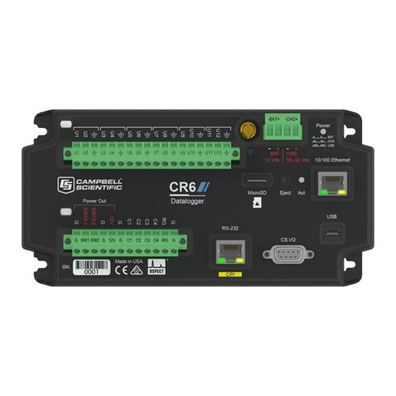
Page 23: Wiring Panel And Terminal Functions
2. Wiring panel and terminal functions The CR6 wiring panel provides ports and removable terminals for connecting sensors, power, and communications devices. It is protected against surge, over-voltage, over-current, and reverse power. The wiring panel is the interface to most data logger functions so studying it is a good way to get acquainted with the data logger. - Page 24 Table 2-1: Analog input terminal functions U1 U2 U3 U4 U5 U6 U7 U8 U9 U10 U11 U12 RG ü ü ü ü ü ü ü ü ü ü ü ü Single-Ended Voltage Differential Voltage ü ü ü ü ü ü...
- Page 25 Table 2-4: Voltage output terminal functions U1-U12 C1-C4 SW12-1 SW12-2 ü ü 3.3 VDC ü ü ü 5 VDC ü ü ü 12 VDC C and even numbered U terminals have limited drive capacity. Voltage levels are configured in pairs. Table 2-5: Communications terminal functions 232/ ü...
-
Page 26: Power Input
Table 2-6: Digital I/O terminal functions U1-U12 C1-C4 ü ü General I/O ü ü Pulse-Width Modulation Output ü ü Timer Input ü ü Interrupt ü ü Quadrature 2.1 Power input The data logger requires a power supply. It can receive power from a variety of sources, operate for several months on non-rechargeable batteries, and supply power to many sensors and devices. -
Page 27: Powering A Data Logger With A Vehicle
Troubleshooting power supplies (p. 136) for more information. Following is a list of CR6 power input terminals and the respective power types supported. BAT terminals: Voltage input is 10 to 18 VDC. This connection uses the least current since the internal data logger charging circuit is bypassed. If the voltage on the BAT terminals exceeds 19 VDC, power is shut off to certain parts of the data logger to prevent damaging connected sensors or peripherals. -
Page 28: Power Led Indicator
See the CRBasic Editor help for detailed instruction information and program examples: https://help.campbellsci.com/crbasic/cr6/. CS I/O port: used to communicate with and often supply power to Campbell Scientific peripheral devices. CAUTION: Voltage levels at the 12V and switched SW12 terminals, and pin 8 on the CS I/O port, are tied closely to the voltage levels of the main power supply. -
Page 29: Grounds
NOTE: Resistance to ground input for non-isolated 0-20 mA and 4-20 mA current loop measurements is available in CR6 data loggers with serial numbers 7502 and greater. These data loggers have two blue stripes on the label. Earth Ground Lug ( ) - connection point for heavy-gage earth-ground wire. A good earth connection is necessary to secure the ground potential of the data logger and shunt transients away from electronics. -
Page 30: Communications Ports
A good earth (chassis) ground will minimize damage to the data logger and sensors by providing a low-resistance path around the system to a point of low potential. Campbell Scientific recommends that all data loggers be earth grounded. All components of the system (data loggers, sensors, external power supplies, mounts, housings) should be referenced to one common earth ground. -
Page 31: Usb Device Port
Campbell Scientific data logger communications ports include: CS I/O RS-232/CPI USB Device Ethernet C and U terminals 2.4.1 USB device port One USB device port supports communicating with a computer through data logger support software or through virtual Ethernet (RNDIS), and provides 5 VDC power to the data logger (powering through the USB port has limitations - details are available in the specifications). -
Page 32: Rs-232, Rs-485, Ttl, And Lvttl Ports
RS-232 ports are not isolated. 2.4.3.3 SDM ports SDM is a protocol proprietary to Campbell Scientific that supports several Campbell Scientific digital sensor and communications input and output expansion peripherals and select smart sensors. It uses a common bus and addresses each node. CRBasic SDM device and sensor instructions configure terminals C1, C2, and C3 together to create an SDM port. -
Page 33: Rs-232/Cpi Port
It consists of a physical layer definition and a data protocol. CDM devices are similar to Campbell Scientific SDM devices in concept, but the CPI bus enables higher data-throughput rates and use of longer cables. CDM devices require more power to operate in general than do SDM devices. -
Page 34: Programmable Logic Control
Low-power bus: Sets bus and modules to low power. When used with a Campbell Scientific RJ45-to-DB9 converter cable, the RS-232/CPI port can be used as an RS-232 port. It defaults to 115200 bps (in autobaud mode), 8 data bits, no parity, and 1 SerialOpen() stop bit. - Page 35 WriteIO() instructions. See the CRBasic Editor help for detailed instruction information and program examples: https://help.campbellsci.com/crbasic/cr6/. Other functions include device-driven interrupts, asynchronous communications and SDI-12 communications. The high voltage for these terminals defaults to 5 V, but it can be changed to 3.3 V using the PortPairConfig() instruction.
- Page 36 In the case of a cell modem, control is based on time. The modem requires 12 VDC power, so connect its power wire to a data logger SW12 terminal. The following code snip turns the modem TimeIsBetween() on for the first ten minutes of every hour using the instruction embedded If/Then in an...
-
Page 37: Setting Up The Cr6
3. Setting up the CR6 The basic steps for setting up your data logger to take measurements and store data are included in the following sections: 3.1 Setting up communications with the data logger 3.2 Testing communications with EZSetup 3.3 Making the software connection 3.4 Creating a Short Cut data logger program... -
Page 38: Usb Or Rs-232 Communications
4. If prompted, select the Direct Connect connection type and click Next. 5. If this is the first time connecting this computer to a CR6 via USB, click Install USB Driver, select your data logger, click Install, and follow the prompts to install the USB drivers. -
Page 39: Virtual Ethernet Over Usb (Rndis)
(p. 41) for more information. 3.1.2 Virtual Ethernet over USB (RNDIS) CR6 series dataloggers with OS version 7 or greater support RNDIS (virtual Ethernet over USB). This allows the data logger to communicate via TCP/IP over USB. Watch a video https://www.campbellsci.com/videos/ethernet-over-usb... -
Page 40: Ethernet Communications Option
3.1.3 Ethernet communications option The CR6 offers a 10/100 Ethernet connection. Use Device Configuration Utility to enter the data logger IP Address, Subnet Mask, and IP Gateway address. After this, use the EZSetup Wizard to set up communications with the data logger. -
Page 41: Configuring Data Logger Ethernet Settings
3. Using data logger support software (LoggerNet, PC400, or PC200W), open Device Configuration Utility 4. Select the CR6 Series data logger from the list 5. Select the port assigned to the data logger from the Communication Port list. If connecting via Ethernet, select Use IP Connection. -
Page 42: Ethernet Leds
PC200W does not support IP connections. 2. Click Next. 3. Select the CR6 Series from the list, enter a name for your station (for example, a site or project name), Next. 4. Select the IP Port connection type and click Next. -
Page 43: Wi-Fi Communications Option
By default, the CR6-WIFI is configured to host a Wi-Fi network. The LoggerLink mobile app for iOS and Android can be used to connect with a CR6-WIFI. Up to eight devices can connect to a network created by a CR6. The setup follows the same steps shown in this video:... -
Page 44: Connecting Your Computer To The Data Logger Over Wi-Fi
1. Open the Wi-Fi network settings on your computer. 2. Select the Wi-Fi-network hosted by the data logger. The default name is CR6 followed by the serial number of the data logger. In the previous image, the Wi-Fi network is CRxxx. -
Page 45: Configuring Data Loggers To Join A Wi-Fi Network
(p. 41) for more information. 3.1.4.4 Configuring data loggers to join a Wi-Fi network By default, the CR6-WIFI is configured to host a Wi-Fi network. To set it up to join a network: 1. Ensure your CR6-WIFI is connected to an antenna and power. -
Page 46: Wi-Fi Led Indicator
3.1.5 Radio communications option CR6-RF data loggers include radio options. The RF407-series frequency-hopping spread- spectrum (FHSS) radio options include the RF407, RF412, RF422, and RF427. The RF451, another radio option, has a 902-to-928 MHz operating-frequency range typically used for long-range communications. -
Page 47: Configuration Options
RF427 radio options, unless otherwise noted. Similarly, the RF407-series standalone, or independent radio represents each of the RF407, RF412, RF422, and RF427 models, unless otherwise noted. 3.1.5.1 Configuration options The most frequently used configurations with the RF-series data logger and RF-series radio include the following: 3. Setting up the CR6... -
Page 48: Rf407-Series Radio Communications With One Or More Data Loggers
NOTE: This procedure assumes the RF407 series devices are using factory default settings. Configuring the RF407-Series radio Configure the RF407-Series radio connected to the computer (see image in Configuration options (p. 29) for reference). 3. Setting up the CR6... -
Page 49: Setting Up Communications Between The Rf407-Series Data Logger And The Computer
7. Select the communication port used to communicate with the RF407-series radio from the COM Port list. (Note that the RF407-series radio to RF407-series data logger link is not indicated in the LoggerNet Setup Standard View.) 3. Setting up the CR6... -
Page 50: Rf407-Series Radio Communications With Multiple Data Loggers Using One Data Logger As A Router
This type of network configuration is useful for communicating around an obstacle, such as a hill or building, or to reach longer distances. To configure an RF407-series radio to communicate with multiple data loggers through a router, you must complete the following steps (instruction follows): 3. Setting up the CR6... -
Page 51: Configuring The Rf407-Series Radio
2. Using Device Configuration Utility , connect to the RF407-series data logger that will serve as a router. 3. On the Deployment > Datalogger tab, assign a unique PakBus Address (see PakBus communications (p. 103) for more information). 3. Setting up the CR6... -
Page 52: Adding Routing Data Logger To Loggernet Network
9. In the Entire Network pane on the left side of the window, select the router data logger (CR6Series) from the list. 10. On the Hardware tab on the right, type the PakBus Address you assigned to the router data logger in Device Configuration Utility. 3. Setting up the CR6... -
Page 53: Adding Leaf Data Loggers To The Network
To configure an RF451 radio to communicate with the data logger, you must complete the following steps (detailed instruction follows): Ensure your data logger and RF451 radio are connected to an antenna and power. Configure the RF451 radio that will be connected to the computer using Device Configuration Utility. 3. Setting up the CR6... -
Page 54: Configuring The Rf451 Radio Connected To The Computer
1. Ensure your RF451 data logger is connected to an antenna and power. 2. Using Device Configuration Utility, connect to the RF451 data logger. 3. On the Deployment | Datalogger tab, assign a unique PakBus address. 3. Setting up the CR6... - Page 55 10. Click Next. 11. By default, the data logger does not use a security code or a PakBus encryption key. Therefore, the Security Code can be left at 0 and the PakBus Encryption Key can be left 3. Setting up the CR6...
-
Page 56: Rf451 Radio Communications With Multiple Dataloggers Using One Data Logger As A Repeater
(Connect to each data logger, and set the PakBus Address on the Deployment | Datalogger tab.) Configure one data logger to act as a repeater. Use data logger support software to set up communication between the computer and the dataloggers. 3. Setting up the CR6... -
Page 57: Configuring The Rf451 Radio Connected To The Computer
2. Using Device Configuration Utility, connect to the RF451 data logger. 3. On the Deployment tab, click the Com Ports Settings sub-tab. 4. From the Select the ComPort list, select RF. 3. Setting up the CR6... -
Page 58: Adding The Repeater Data Logger To The Loggernet Network
CR6Series. 2. With the newly added data logger selected in the Entire Network pane, set the PakBus Address to the address that was assigned to the leaf data logger in Device Configuration Utility. 3. Setting up the CR6... -
Page 59: Using Additional Communication Methods
(p. 20) for more information). Alternatively, you can double-click a data logger from the station list to open the EZ Setup Wizard and access the Communication Test step from the left side of the window. 3. Setting up the CR6... - Page 60 5. The data logger ships with a default GettingStarted program. If the data logger does not have a program, you can choose to send one by clicking Select and Send Program. Click Next. 6. LoggerNet only - Use the following instructions or watch the Scheduled/Automatic Data Collection video 3. Setting up the CR6...
-
Page 61: Making The Software Connection
Short Cut. For more complex programming the CRBasic editor is used. The program file may use the extension .CR6, .CRB or .DLD. Data logger programs are executed on a precise schedule termed the scan interval, based on the data logger internal clock. - Page 62 Use the Short Cut software to generate a program for your data logger. Short Cut is included with your data logger support software. This section will guide you through programming a CR6 data logger to measure the voltage of the data logger power supply, the internal temperature of the data logger, and a thermocouple.
- Page 63 Generally it is best to collect data first; so, we recommend sending the program using the instructions in Sending a program to the data logger (p. 46). 3. Setting up the CR6...
-
Page 64: Sending A Program To The Data Logger
4. Confirm that you would like to proceed and erase all data tables saved on the data logger. The program will send and compile. 5. Review the Compile Results window for errors, messages and warnings. 3. Setting up the CR6... - Page 65 Click OK. After sending a program, it is a good idea to monitor the Public Table to make sure sensors are taking good measurements. See Working with data (p. 48) for more information. 3. Setting up the CR6...
-
Page 66: Working With Data
4. Working with data 4.1 Default data tables By default, the data logger includes three tables: Public, Status, and DataTableInfo. Each of these tables only contains the most recent measurements and information. The Public table is configured by the data logger program, and updated at the scan interval set within the data logger program, It shows measurement and calculation results as they are made. -
Page 67: Collecting Data
4.2 Collecting data The data logger writes to data tables based on intervals and conditions set in the CRBasic program (see Creating data tables in a program (p. 56) for more information). After the program has been running for enough time to generate data records, data may be collected by using data logger support software. -
Page 68: Viewing Historic Data
3. Select an option for What to Collect. Either option creates a new file if one does not already exist. New data from data logger (Append to data files): Collects only the data in the selected tables stored since the last data collection and appends this data to the end of the existing table files on the computer. -
Page 69: Variables
As Long specifies the variable as a 32 bit integer. There are two possible reasons a user would do this: (1) speed, since the CR6 Operating System can do math on integers faster than with Floats, and (2) resolution, since the Long has 31 bits compared to the 24 bits in the Float. -
Page 70: Data Storage
While (IEEE 4 byte floating point) is used for variables and internal calculations, adequate for most stored data. Campbell Scientific 2 byte floating point (FP2)provides 3 or 4 IEEE4 significant digits of resolution, and requires half the memory space as (2 bytes per value vs 4). -
Page 71: About Data Tables
You can retrieve data based on a schedule or by manually choosing to collect data using data logger support software (see Collecting data (p. 49)). Table 4-4: Example data TOA5, MyStation, CR6, 1142, CR6.Std.01, CPU:MyTemperature.CR6, 1958, OneMin TIMESTAMP RECORD BattV_Avg PTemp_C_Avg... -
Page 72: Header Rows
CR6 - Data logger model. 1142 - Data logger serial number. CR6.Std.01 - Data logger OS version. CPU:MyTemperature.CR6 - Data logger program name. Changed by sending a new program (see Sending a program to the data logger (p. 46) for more information). - Page 73 abbreviation of the data process that outputs the data to storage. A list of these abbreviations follows in Data processing abbreviations (p. 55). If a field is an element of an array, the field name will be followed by a indices within parentheses that identify the element in the array.
-
Page 74: Data Records
Typically, data tables are called by the instruction once each Scan. These instructions include: DataTable() 'Output Trigger Condition(s) 'Output Processing Instructions EndTable See the CRBasic Editor help for detailed instruction information and program examples: https://help.campbellsci.com/crbasic/cr6/. 4. Working with data... - Page 75 Use the DataTable() instruction to define the number of records, or rows, allocated to a data table. You can set a specific number of records, which is recommended for conditional tables, or allow your data logger to auto-allocate table size. With auto-allocation, the data logger balances the memory so the tables “fill up”...
-
Page 76: Data Memory
Data concerning the data logger memory are posted in the Status and DataTableInfo tables. For additional information on these tables, see Information tables and settings (advanced) (p. 163). For additional information on data logger memory, visit the Campbell Scientific blog article, "How to Know when Your Datalogger Memory is Getting Full." 5.2 Memory allocation Data table SRAM and the CPU drive are automatically partitioned by the data logger. -
Page 77: Sram
5.3 SRAM SRAM holds program variables, communications buffers, final-data memory, and, if allocated, the USR drive. An internal lithium battery retains this memory when primary power is removed. The structure of the data logger SRAM memory is as follows: Static Memory: This is memory used by the operating system, regardless of the running program. -
Page 78: Usr Drive
USR drive: Optionally allocated. Holds image files. Holds a copy of final-data memory TableFile() FileRead() when instruction used. Provides memory for FileWrite() operations. Managed in File Control. Status reported in Status table fields USRDriveSize and USRDriveFree. 5.3.1 USR drive Battery-backed SRAM can be partitioned to create a FAT USR drive, analogous to partitioning a second drive on a computer hard disk. -
Page 79: Cpu Drive
Campbell Scientific. These cards are industrial-grade and have passed Campbell Scientific hardware testing. Use of consumer grade cards substantially increases the risk of data loss. Following are listed advantages Campbell Scientific cards have over less expensive commercial-grade cards: Less susceptible to failure and data loss. -
Page 80: Formatting Microsd Cards
the card is removed, the size of the table in SRAM is shown. For more information, see File system error codes (p. 161). When a new program is compiled that sends data to the card, the data logger checks if a card is present and if the card has adequate space for the data tables. - Page 81 Red flash: Card read/write activity Solid green: Formatted card inserted, powered up. This LED also indicates it is OK to remove card. The Eject button must be pressed before removing a card to allow the data logger to store buffered data to the card and then power it off. Solid orange: Error Dim/flashing orange: Card has been removed and has been out long enough that CPU memory has wrapped and data is being overwritten without being stored to the card.
-
Page 82: Measurements
6. Measurements 6.1 Voltage measurements 6.2 Current-loop measurements 6.3 Resistance measurements 6.4 Period-averaging measurements 6.5 Pulse measurements 6.6 Vibrating wire measurements 6.7 Sequential and pipeline processing modes 6.1 Voltage measurements Voltage measurements are made using an Analog-to-Digital Converter (ADC). A high- impedance Programmable-Gain Amplifier (PGA)amplifies the signal. -
Page 83: Single-Ended Measurements
WARNING: Sustained voltages in excess of ±20 V applied to terminals configured for analog input will damage CR6 circuitry. 6.1.1 Single-ended measurements A single-ended measurement measures the difference in voltage between the terminal configured for single-ended input and the reference ground. For example, single-ended channel 1 is comprised of terminals U1 and . -
Page 84: Differential Measurements
Improving voltage measurement quality 147) and Analog measurements specifications (p. 216). 6.2 Current-loop measurements NOTE: This information applies to CR6 data loggers with serial numbers 7502 and greater. These data loggers have two blue stripes on the label. 6. Measurements... -
Page 85: Example Current-Loop Measurement Connections
CurrentSE RG terminals can be configured to make analog current measurements using the instruction. When configured to measure current, terminals each have an internal resistance of 101 Ω in the current measurement loop. The return path of the sensor must be connected directly to the G terminal closest to the terminal used. - Page 86 Sensor Type Connection Example 2-wire transmitter using data logger power 2-wire transmitter using external power 3-wire transmitter using data logger power 6. Measurements...
-
Page 87: Resistance Measurements
Sensor Type Connection Example 3-wire transmitter using external power 4-wire transmitter using data logger power 4-wire transmitter using external power 6.3 Resistance measurements Bridge resistance is determined by measuring the difference between a known voltage or current applied to the excitation (input) of a resistor bridge and the voltage measured on the output arm. -
Page 88: Resistance Measurements With Voltage Excitation
- four-wire half bridge BrFull() - four-wire full bridge BrFull6W() - six-wire full bridge See the CRBasic Editor help for detailed instruction information and program examples: https://help.campbellsci.com/crbasic/cr6/. Resistive-Bridge Type and CRBasic Instruction and Relational Formulas Circuit Diagram Fundamental Relationship Half Bridge... - Page 89 = sensor return voltages; R = fixed, bridge or completion resistor; R variable or sensing resistor. Campbell Scientific offers terminal input modules to facilitate this measurement. Offset voltage compensation applies to bridge measurements. In addition to RevDiff and MeasOff parameters discussed in Minimizing offset voltages (p.
-
Page 90: Resistance Measurements With Current Excitation
measurement instructions include the RevEx parameter that provides the option to program a second set of measurements with the excitation polarity reversed. Much of the offset error inherent in bridge measurements is canceled out by setting RevDiff, RevEx, and MeasOff to True. - Page 91 The data logger supplies a precise current from terminals configured for current excitation. Return voltage is measured on U terminals configured for single-ended or differential analog input. U terminals can be configured as current-output terminals under program control for making resistance measurements.
-
Page 92: Strain Measurements
Resistive-Bridge Type and CRBasic Instruction and Relational Formulas Circuit Diagram Fundamental Relationship Three Wire CRBasic Instruction: Resistance3W() Fundamental Relationship Where X = result of the CRBasic bridge measurement instruction with a multiplier of 1 and an offset of 0. Where Ri is the precision internal resistor value that is saved as part of the factory calibration procedure and Rs is the sense resistance. - Page 93 Table 6-1: StrainCalc() configuration codes BrConfig Code Configuration Quarter-bridge strain gage: Half-bridge strain gage. One gage parallel to strain, the other at 90° to strain: Half-bridge strain gage. One gage parallel to +ɛ, the other parallel to -ɛ: Full-bridge strain gage. Two gages parallel to +ɛ, the other two parallel to -ɛ: 6.
-
Page 94: Ac Excitation
Table 6-1: StrainCalc() configuration codes BrConfig Code Configuration Full-bridge strain gage. Half the bridge has two gages parallel to +ɛ and -ɛ, and the other half to +νɛ and -νɛ Full-bridge strain gage. Half the bridge has two gages parallel to +ɛ and -νɛ... -
Page 95: Accuracy For Resistance Measurements
Voltage Measurement Accuracy, Self- Calibration, and Ratiometric Measurements NOTE: Error discussed in this section and error-related specifications of the CR6 do not include error introduced by the sensor, or by the transmission of the sensor signal to the data logger. -
Page 96: Pulse Measurements
The measurement is performed as follows: low-level signals are amplified prior to a voltage comparator. The internal voltage comparator is referenced to the programmed threshold. The threshold parameter allows referencing the internal voltage comparator to voltages other than 0 V. For example, a threshold of 2500 mV allows a 0 to 5 VDC digital signal to be sensed by the internal comparator without the need for additional input conditioning circuitry. - Page 97 The data logger includes terminals that are configurable for pulse input as shown in the following image. Table 6-2: Pulse input terminals and the input types they can measure Input Type Pulse Input Terminal C (all) High-frequency U (all) Low-level AC U (even numbered terminals) Switch-closure C (all)
-
Page 98: Low-Level Ac Measurements
Low-level AC signals cannot be measured directly by C terminals. Peripheral terminal expansion modules, such as the Campbell Scientific LLAC4, are available for converting low-level AC signals to square-wave signals measurable by C terminals. For more information, see Pulse measurement specifications (p. -
Page 99: U Terminals
An internal 100 kΩ pull-up resistor pulls an input to 5 VDC with the switch open, whereas a switch-closure to ground pulls the input to 0 V. CRBasic instruction: PulseCount(). See the CRBasic Editor help for detailed instruction information and program examples: https://help.campbellsci.com/crbasic/cr6/. 6. Measurements... -
Page 100: C Terminals
Switch Closure on U or C Terminal Open Collector on U or C Terminal 6.5.3.2 C terminals Switch-closure mode is a special case edge-count function that measures dry-contact switch- closures or open collectors. The operating system filters bounces. CRBasic instruction: PulseCount(). See also Pulse measurement specifications (p. -
Page 101: Timer Input Nan Conditions
6.5.4.3 Timer input NAN conditions TimerInput() NAN is the result of a measurement if one of the following occurs: Measurement timer expires The signal frequency is too fast For more information, see: Pulse measurement specifications (p. 221) Digital input/output specifications (p. -
Page 102: Pulse Measurement Tips
Counters will overflow if accumulated counts exceed 4,294,967,296 (2 ), resulting in erroneous measurements. See the CRBasic Editor help for detailed instruction information and program examples: https://help.campbellsci.com/crbasic/cr6/. PulseCount() Counts are the preferred output option when measuring the number of tips from a tipping-bucket rain gage or the number of times a door opens. -
Page 103: Pulse Count Resolution
A thermistor included in most sensors can be measured to compensate for temperature errors. The following image provides some examples for connecting vibrating wire sensors to the CR6. You can use the Short Cut software to create a program and display a wiring diagram for most types of vibrating wire sensors. -
Page 104: Vspect
6.6.1 VSPECT® Measuring the resonant frequency by means of period averaging is the classic technique, but Campbell Scientific has developed static and dynamic spectral-analysis techniques (VSPECT) that produce superior noise rejection, higher resolution, diagnostic data, and, in the case of dynamic VSPECT, measurements up to 333.3 Hz. -
Page 105: Low Signal Strength Amplitude Warning
Low signal strength amplitude warning When the response amplitude is measured as less than 0.01 mV RMS, the Resonant Frequency value reports NAN indicating that low signal strength amplitudes have occurred. The 0.01 mV VibratingWire() threshold can be modified in the instruction. -
Page 106: Preventing Spectral Leakage
The exact time at which measurements are made in sequential mode may vary if other measurements or processing are made conditionally, if there is heavy communications activity, or if other interrupts occur (such as accessing a Campbell Scientific memory card). 6. Measurements... -
Page 107: Pipeline Mode
6.7.2 Pipeline mode Pipeline mode handles measurement, most digital, and processing tasks separately, and, in many cases, simultaneously. Measurements are scheduled to execute at exact times and with the highest priority, resulting in more precise timing of measurements, and usually more efficient processing and power consumption. -
Page 108: Communications Protocols
7. Communications protocols Data loggers communicate with data logger support software, other Campbell Scientific data loggers, and other hardware and software using a number of protocols including PakBus, Modbus, DNP3, CPI, SPI, and TCP/IP. Several industry-specific protocols are also supported. -
Page 109: General Serial Communications
Communications ports (p. 12) for information on port configuration options. CRBasic instructions for general serial communications include: SerialOpen() SerialClose() SerialIn() SerialInRecord() SerialInBlock() SerialOut() SerialOutBlock() See the CRBasic Editor help for detailed instruction information and program examples: https://help.campbellsci.com/crbasic/cr6/. 7. Communications protocols... -
Page 110: Modbus Communications
Why Modbus Matters: An Introduction How to Access Live Measurement Data Using Modbus Using Campbell Scientific Dataloggers as Modbus Slave Devices in a SCADA Network Because Modbus has a set command structure, programming the data logger to get data from field instruments can be much simpler than from some other serial sensors. -
Page 111: About Modbus
Not only can intelligent devices such as microcontrollers and programmable logic controllers (PLCs) communicate using Modbus, but many intelligent sensors have a Modbus interface that enables them to send their data to host systems. Examples of using Modbus with Campbell Scientific data loggers include: Interfacing data loggers and Modbus-enabled sensors. -
Page 112: Modbus Protocols
7.2.2 Modbus protocols There are three standard variants of Modbus protocols: Modbus RTU — Modbus RTU is the most common implementation available for Modbus. Used in serial communications, data is transmitted in a binary format. The RTU format follows the commands/data with a cyclic redundancy check checksum. NOTE: The Modbus RTU protocol standard does not allow a delay between characters of 1.5 times or more the length of time normally required to receive a character. -
Page 113: Understanding Modbus Terminology
Campbell Scientific data loggers support Modbus RTU, Modbus ASCII, and Modbus TCP protocols. If the connection is over IP, Campbell Scientific data loggers always use Modbus TCP. Modbus slave functionality over other comports use RTU. When acting as a master, the data... -
Page 114: About Modbus Programming
Campbell Scientific data loggers can be programmed to be a Modbus master or Modbus slave - or even both at the same time! This proves particularly helpful when your data logger is a part of two wider area networks. -
Page 115: Function Codes
Little-endian format reverses this order: the sequence stores the least significant byte first and the most significant byte last. Endianness is used in some Modbus programming so it is important to note that the CR6 is a big-endian instrument. 7.2.6.2 Function codes A function code tells the slave which storage entity to access and whether to read from or write to that entity. -
Page 116: Modbus Information Storage
In a 16-bit memory location, a 4-byte value takes up two registers. The Modbus protocol always refers to data registers with a starting address number, and a length to indicate how many registers to transfer. Campbell Scientific uses 1-based numbering (a common convention for numbering registers in ModbusMaster() equipment) in the instruction. -
Page 117: Data Types
are read and manipulated with their own function codes, apart from the registers. Many modern devices do not utilize coils at all. When working with coils, the data logger requires Boolean variables. When reading coils, each Boolean in an array will hold the state of one coil. A value of True will set the coil, a value of False will unset the coil. -
Page 118: Signed 32-Bit Integer
Long holding it. 32-Bit floating point 32-bit floating point values use 2 registers each. This is the default FLOAT data type in Campbell Scientific data loggers. Select the appropriate ModbusOption to avoid post-processing. -
Page 119: Result Code -02: Illegal Data Address
for devices to have holding registers where read-only and read/write registers are mapped next to each other. An uncommon cause for the -01 result is a device with an incomplete implementation of Modbus. Some devices do not fully implement parsing Modbus commands. Instead, they are hardcoded to respond to certain Modbus messages. -
Page 120: Ip Address
Settings Editor: Ethernet | {information box} to see the assigned IP address. The CR6 provides a DNS client that can query a DNS server to determine if an IP address has been mapped to a hostname. If it has, then the hostname can be used interchangeably with the IP address in some data logger instructions. -
Page 121: Serial Peripheral Interface (Spi) And I2C
For additional information on I2C, see www.i2c-bus.org. 7.6 PakBus communications PakBus is a Campbell Scientific communications protocol. By using signed data packets, PakBus increases the number of communication and networking options available to the data logger. The data logger allows PakBus communications on all available communications ports. For... -
Page 122: Communications
SDI12Recorder() SDI12SensorSetup() SDI12SensorResponse() See the CRBasic Editor help for detailed instruction information and program examples: https://help.campbellsci.com/crbasic/cr6/. The data logger uses SDI-12 version 1.4. 7.7.1 SDI-12 transparent mode System operators can manually interrogate and enter settings in probes using transparent mode. - Page 123 To enter the SDI-12 transparent mode, enter the data logger support software terminal emulator: 1. Press Enter until the data logger responds with the prompt CR6>. 2. Type SDI12 at the prompt and press Enter. 3. In response, the query Select SDI12 Port is presented with a list of available ports.
-
Page 124: Transparent Mode Commands
1. Enter the terminal mode as described previously. 2. Press Enter until a CR6> prompt appears. 3. Type W and then press Enter. 4. In response, the query Select SDI12 Port: is presented with a list of available ports. Enter the port number assigned to the terminal to which the SDI-12 sensor is connected, and press Enter. -
Page 125: Programming The Data Logger To Act As An Sdi-12 Sensor
SDI-12 sensor. A common use of this feature is to copy data from the data logger to other Campbell Scientific data loggers over a single data-wire interface (terminal configured for SDI-12 to terminal configured for SDI-12), or to copy data to a third-party SDI-12 recorder. - Page 126 Power Usage: Quiescent: 0.25 mA Active: 66 mA Measurement: 120 mA Measurement time: 15 s Timeout: 15 s Probes 1, 2, 3, and 4 are connected to SDI-12 port C1. The time line in the following table shows a 35-second power-usage profile example. For most applications, total power usage of 318 mA for 15 seconds is not excessive, but if 16 probes were wired to the same SDI-12 port, the resulting power draw would be excessive.
-
Page 127: Cr6 Maintenance
Desiccant should be changed periodically. If sending the data logger to Campbell Scientific for calibration or repair, consult first with Campbell Scientific. If the data logger is malfunctioning, be prepared to perform some... -
Page 128: About Background Calibration
About background calibration (p. 110). You can download and print calibration certificates for many products you have purchased by logging in to the Campbell Scientific website and going to: https://www.campbellsci.com/calcerts. NOTE: Note, you will need your product's serial number to access its certificate. -
Page 129: Data Logger Security
Tracking Operating System, Run, and Program signatures. Encrypting program files if they contain sensitive information (see CRBasic help FileEncrypt() instruction or use the CRBasic Editor File menu, Save and Encrypt option). FileManage() Hiding program files for extra protection (see CRBasic help instruction). 8. CR6 maintenance... -
Page 130: Security Codes
0, any security code level greater than it will be set to 0. For example, if Security 2 is 0 then Security 3 is automatically set to 0. Security codes are unlocked in reverse order: Security 3 before Security 2, Security 2 before Security 1. 8. CR6 maintenance... -
Page 131: Creating A .Csipasswd File
.csipasswd file. The web interface provides access to real-time and stored data logger data. For more information on the web interface, watch an instructional video. NOTE: Ethernet over USB (RNDIS) is considered a direct communications connection. Therefore, it is a trusted connection and csipasswd does not apply. 8. CR6 maintenance... -
Page 132: Command Syntax
8.2.2.1 Command syntax Syntax for the commands sent to the web server generally follows the form of: 8. CR6 maintenance... -
Page 133: Data Logger Enclosures
Do not completely seal the enclosure if lead-acid batteries are present; hydrogen gas generated by the batteries may build to an explosive concentration. The following details a typical installation using a Campbell Scientific enclosure. The data logger has mounting holes through which small screws are inserted into nylon anchors in the backplate. -
Page 134: Internal Battery
Time. Clock will need resetting when the battery is replaced. Final-memory data tables. A replacement lithium battery can be purchased from Campbell Scientific or another supplier. AA, 2.4 Ah, 3.6 VDC (Tadiran TL 5903/S) for battery-backed SRAM and clock. 3-year life with no external power source. -
Page 135: Replacing The Internal Battery
Any damage made to the data logger during user replacement of the internal battery is not covered under warranty. 1. Remove the screws from the back panel. 2. Pull the bottom and top of the data logger apart. 3. Disconnect the battery connector. 8. CR6 maintenance... -
Page 136: Electrostatic Discharge And Lightning Protection
While elaborate, expensive, and nearly infallible lightning protection systems are on the market, Campbell Scientific, for many years, has employed a simple and inexpensive design that protects most systems in most circumstances. The system consists of a lightning rod, metal mast, heavy-gauge ground wire, and ground rod to direct damaging current away from the data logger. - Page 137 Spark-gap protection is usually an option with these products; so, request it when ordering. Spark gaps must be connected to earth (chassis) ground. For detailed information on grounding, see Grounds (p. 11). 8. CR6 maintenance...
-
Page 138: Power Budgeting
Power output specifications (p. 213) 8.7 Updating the operating system Campbell Scientific posts operating system (OS) updates at www.campbellsci.com/downloads when they become available. It is recommended that before deploying instruments, you check operating system versions and update them as needed. The data logger operating system version is shown in the Status table, Station Status Summary, and Device Configuration Utility 8. -
Page 139: Sending An Operating System To A Local Data Logger
8. Navigate to the C:\Campbellsci\Lib\OperatingSystems folder. 9. Ensure Datalogger Operating System Files (*.obj) is selected in the Files of type list, select the new OS .obj file, and click Open to update the OS on the data logger. 8. CR6 maintenance... -
Page 140: Sending An Operating System To A Remote Data Logger
8.7.2 Sending an operating system to a remote data logger NOTE: This information applies to CR6 dataloggers with serial numbers 7502 and newer. These dataloggers have two blue stripes on the label. For CR6 dataloggers with serial numbers 7501 and older, see: Video | Sending an OS to a Remote Datalogger. -
Page 141: File Management Via Powerup.ini
If no change is made to the Run Now program, but the Run on Power Up program is changed, the new Run on Power Up program runs. If neither Run on Power Up nor Run Now programs are changed, the previous Run on Power Up program runs. 8. CR6 maintenance... -
Page 142: Syntax
Copies a program file to a drive and sets the program to Run Run now, Now. Data on a memory card from the previously running preserve data program will be preserved if table structures have not changed. 8. CR6 maintenance... -
Page 143: Example Powerup.ini Files
'Device = device to which File is copied. Defaults to CPU 'Command,File,Device 13,Write2CRD_2.CR6,cpu: Example: Run Program on Power Up 'Copy program file pwrup.CR6 from the external drive to CPU: 'File will run only when the data logger is powered-up later. 2,pwrup.CR6,cpu: Example: Format the USR Drive 5,,usr: 8. - Page 144 'A program file is carried on an SC115 Flash Memory drive. 'Do not copy program file from SC115 'Run program always, erase data. 13,toobigforcpu.CR6,usb: Example: Always Run Program, Erase Data 13,pwrup_1.CR6,cpu: Example: Run Program Now and Erase Data Now 14,run.CR6,cpu: 8. CR6 maintenance...
-
Page 145: Tips And Troubleshooting
9. Tips and troubleshooting Start with these basic procedures if a system is not operating properly. 1. Using a voltmeter, check the voltage of the primary power source at the CHG and BAT terminals on the face of the data logger, it should be 10 to 18 VDC. If connecting to a power source via the CHG terminals, voltage measured should be 16 to 32 VDC. -
Page 146: Checking Station Status
9.11 Field calibration 9.12 File system error codes 9.13 File name and resource errors 9.14 Background calibration errors Also, consider checking, or posting your question to, the Campbell Scientific user forum http://www.campbellsci.com/forum. Our web site https://www.campbellsci.com has additional manuals (with example programs), FAQs, specifications and compatibility information for all of our products. -
Page 147: Viewing Station Status
Check your data logger operating system version; recent operating system versions have improved stability of IP communications. If any of these are not the apparent cause, contact Campbell Scientific for assistance (see https://www.campbellsci.com/support). Causes that may require assistance include:... -
Page 148: Results For Last Program Compiled
9.1.3 Results for last program compiled Messages generated by the data logger at program upload and as the program runs are reported here. Warnings indicate that an expected feature may not work, but the program will still operate. Errors indicate that the program cannot run. For more information, see CRBasic program errors (p. -
Page 149: Timekeeping
NANs are expected in the following conditions: Input signals exceed the voltage range chosen for the measurement. An invalid SDI-12 command is sent An SDI-12 sensor does not respond or aborts without sending data Undefined arithmetic expressions, such as 0 ÷ 0. NAN is a constant that can be used in expressions. -
Page 150: Clock Best Practices
9.3.1 Clock best practices When setting the clock with LoggerNet, initiate it manually during a maintenance period when the data logger is not actively writing to Data Tables. Click Set in the Clocks field of the LoggerNet Connect Screen. If you are going to use automated clock check with LoggerNet (clock settings can be found on the LoggerNet Setup Standard View Clock tab). -
Page 151: Crbasic Program Errors
See the CRBasic Editor help for detailed instruction information and program examples: https://help.campbellsci.com/crbasic/cr6/. 9.4 CRBasic program errors Analyze data soon after deployment to ensure the data logger is measuring and storing data as intended. Most measurement and data-storage problems are a result of one or more CRBasic program bugs. -
Page 152: Program Compiles But Does Not Run Correctly
Information tables and settings (advanced) (p. 163). See the CRBasic Editor help for detailed instruction information and program examples: https://help.campbellsci.com/crbasic/cr6/. 9.5 Troubleshooting Radio Communications If there are intermittent communication problems when connecting via radio, there may be another network in the area causing interference. To help remove the interference, use Device Configuration Utility to change the Network ID and RF Hop Sequence in all RF407, RF412, and RF422 radios within a network (standalone or included in a data logger) to another value. -
Page 153: Resetting The Data Logger
example, the Network ID in all devices could be set to 1726, and the RF Hop Sequence in all devices could be set to 1. The Network ID can be any number between 0 and 32767. The RF Hop Sequence can be any number between 0 and 7 in an RF407 or RF412 network; it can be any number between 0 and 9 in an RF422 network. -
Page 154: Manual Data Table Reset
When a program compiles, all variables are initialized. A program is recompiled after a power failure or a manual stop. For instances that require variables to be preserved through a program recompile, consider PreserveVariables(). 9.6.3 Manual data table reset Data table memory is selectively reset from: Datalogger support software: Station Status >... -
Page 155: Using Terminal Mode
Connect window > Datalogger menu item> Terminal Emulator... Device Configuration Utility Terminal tab After entering a terminal emulator, press Enter a few times until the prompt CR6> is returned. Terminal commands consist of specific characters followed by Enter. Sending an H and Enter will return the terminal emulator menu. - Page 156 Lists technical data concerning program scans. time in seconds Serial FLASH data dump Campbell Scientific engineering tool Read clock chip Lists binary data concerning the CR6 clock chip. Status Lists the CR6 Status table. Card status and compile Lists technical data concerning an installed memory errors card.
- Page 157 Table memory is retained. NOTE: When typing REBOOT, characters are not echoed (printed on terminal screen). Issue commands from keyboard that are passed through the CR6 SDI-12 port to the connected device. SDI12 SDI12 talk through Similar in concept to Serial Talk Through. See also SDI-12 transparent mode (p.
-
Page 158: Serial Talk Through And Comms Watch
40 seconds to any value ranging from 1 to 86400 seconds (86400 seconds = 1 day). When using options P or W in a terminal session, consider the following: Concurrent terminal sessions are not allowed by the CR6. Opening a new terminal session will close the current terminal session. - Page 159 To enter the SDI-12 transparent mode, enter the data logger support software terminal emulator: 1. Press Enter until the data logger responds with the prompt CR6>. 2. Type SDI12 at the prompt and press Enter. 3. In response, the query Select SDI12 Port is presented with a list of available ports.
-
Page 160: Transparent Mode Commands
4. In response, the query Select SDI12 Port: is presented with a list of available ports. Enter the port number assigned to the terminal to which the SDI-12 sensor is connected, and press Enter. 5. In answer to Enter timeout (secs): type 100 and press Enter. 6. -
Page 161: Common Causes
9.9.1 Common causes Some of the common causes of ground loops include the following: The drain wire of a shielded cable is connected to the local ground at both ends, and the ground is already being carried by a conductor inside the cable. In this case, two wires, one on either side of the cable shield, are connected to the ground nodes at both ends of the cable. - Page 162 Relatively small electromagnetic energy: This could come from AC current on a nearby power cable, or RF energy transmitting through the air, and can cause electrical noise that either corrupts an analog signal or disrupts digital communications. Larger electromagnetic energy: The antenna loop scenario can have a more damaging effect when a large current is discharged nearby.
-
Page 163: Severing A Ground Loop
9.9.3 Severing a ground loop To avoid or eliminate ground loops, when they are detected, requires severing the loop. Suggestions for severing ground loops include: Connect the shield wire of a signal cable to ground only at one end of the cable. Leave the other end floating (not connected to ground). - Page 164 Note that the geometry of the electrodes has a great effect on the magnitude of this error. The Delmhorst gypsum block used in the Campbell Scientific 227 probe has two concentric cylindrical electrodes. The center electrode is used for excitation; because it is encircled by the ground electrode, the path for a ground loop through the soil is greatly reduced.
-
Page 165: Improving Voltage Measurement Quality
9.10 Improving voltage measurement quality The following topics discuss methods of generally improving voltage measurements: 9.10.1 Deciding between single-ended or differential measurements 9.10.2 Minimizing ground potential differences 9.10.3 Detecting open inputs 9.10.4 Minimizing power-related artifacts 9.10.5 Filtering to reduce measurement noise 9.10.6 Minimizing settling errors 9.10.7 Factors affecting accuracy 9.10.8 Minimizing offset voltages... -
Page 166: Minimizing Ground Potential Differences
Rapid sampling is required. Single-ended measurement time is about half that of differential measurement time. Sensor is not designed for differential measurements. Some Campbell Scientific sensors are not designed for differential measurement, but the drawbacks of a single-ended measurement are usually mitigated by large programmed excitation and/or sensor output voltages. -
Page 167: Ground Potential Differences
If offset problems occur because of shield or ground wires with large current flow, tying the problem wires into terminals next to terminals configured for excitation and pulse-count should help. Problem wires can also be tied directly to the ground lug to minimize induced single-ended offset voltages. -
Page 168: Minimizing Power-Related Artifacts
voltage through external leakage to ground within the settling time of the measurement. This problem is worse when a long settling time is selected, as more time is given for the input capacitors to discharge to a "normal" level. If the open circuit is at the end of a very long cable, the test pulse may not charge the cable (with its high capacitance) up to a voltage that generates NAN or a distinct error voltage. -
Page 169: Minimizing Electronic Noise
9.10.4.1 Minimizing electronic noise Electronic noise can cause significant error in a voltage measurement, especially when measuring voltages less than 200 mV. So long as input limitations are observed, the PGA ignores voltages, including noise, that are common to each side of a differential-input pair. This is the common- mode voltage. -
Page 170: Filtering To Reduce Measurement Noise
Preventing and Attacking Measurement Noise Problems. 9.10.5.1 CR6 filtering details The data logger utilizes a sigma-delta ADC that outputs digitized data at a rate of 93750 samples per second. User-specified filtering is achieved by averaging several samples from the ADC. -
Page 171: Minimizing Settling Errors
9.10.6.1 Measuring settling time Settling time for a particular sensor and cable can be measured with the CR6. Programming a series of measurements with increasing settling times will yield data that indicate at what settling time a further increase results in negligible change in the measured voltage. - Page 172 CRBasic Example 2: Measuring Settling Time 'This program example demonstrates the measurement of settling time 'using a single measurement instruction multiple times in succession. Public PT(20) 'Variable to hold the measurements DataTable (Settle,True,100) Sample (20,PT(),IEEE4) EndTable BeginProg Scan (1,Sec,3,0) BrFull (PT(1), 1,mV200,U1,U11,1,2500,True,True, 100,15000,1.0,0) BrFull (PT(2), 1,mV200,U1,U11,1,2500,True,True, 200,15000,1.0,0)
-
Page 173: Factors Affecting Accuracy
Each trace in the following image contains all twenty PT() mV/V values (left axis) for a given record number and an average value showing the measurements as percent of final reading (right axis). The reading has settled to 99.5% of the final value by the fourteenth measurement, which is contained in variable PT(14). -
Page 174: Measurement Accuracy Example
9.10.7.1 Measurement accuracy example The following example illustrates the effect percent-of-reading and offset have on measurement accuracy. The effect of offset is usually negligible on large signals. Example: Sensor-signal voltage: approximately 1050 mV VoltDiff() CRBasic measurement instruction: Programmed input-voltage range (Range) : mV 5000 (±5000 mV) Input measurement reversal (RevDiff): True Data logger circuitry temperature: 10°... - Page 175 Using MeasOff = True for better offset compensation. Using excitation reversal (RevEx = True) with bridge measurements. Programming longer settling times. Single-ended measurements are susceptible to voltage drop at the ground terminal caused by return currents from another device that is powered from the data logger wiring panel, such as another manufacturer's communications modem, or a sensor that requires a lot of power.
-
Page 176: Compensating For Offset Voltage
The following table lists some of the tools available to minimize the effects of offset voltages: Table 9-3: Offset voltage compensation options Measure Offset During Background CRBasic Measure Offset Input Reversal Excitation Reversal Calibration Measurement During Measurement (RevDiff=True) (RevEx=True) (RevDiff=False) Instruction (MeasOff=True) (RevEx=False) -
Page 177: Measuring Ground Reference Offset Voltage
For example, if 3 µV offset exists in the measurement circuitry, a 5 mV signal is measured as 5.003 mV. When the input or excitation is reversed, the second sub-measurement is –4.997 mV. Subtracting the second sub-measurement from the first and then dividing by 2 cancels the offset: 5.003 mV –... -
Page 178: Field Calibration
CRBasic program, measurements of a linear sensor can be adjusted by modifying the programmed multiplier and offset applied to the measurement, without modifying or recompiling the CRBasic program. See the CRBasic Editor help for detailed instruction information and program examples: https://help.campbellsci.com/crbasic/cr6/. 9. Tips and troubleshooting... -
Page 179: File System Error Codes
9.12 File system error codes Errors can occur when attempting to access files on any of the available drives. All occurrences are rare, but they are most likely to occur when using optional memory cards. Often, formatting the drive will resolve the error. The errors display in the File Control messages box or in the CardStatus field of the Status table. -
Page 180: File Name And Resource Errors
35 DMA memory boundary crossing error 36 Miscellaneous I/O error 37 Pipe size of 0 requested 38 Memory-release error (relmem) 39 FAT sectors unreadable (all copies) 40 Bad BPB sector 41 Time-out waiting for filesystem available 42 Controller failure error 43 Pathname exceeds _MAX_PATHNAME 9.13 File name and resource errors The maximum file name size that can be stored, run as a program, or FTP transferred in the data... -
Page 181: Information Tables And Settings (Advanced)
Information tables and settings consist of fields, settings, and system information essential to setup, programming, and debugging of many advanced CR6 systems. In many cases, the info tables and settings keyword can be used to pull that field into a running CRBasic program. There are several locations where this system information and settings are stored or changed: Status table: The Status table is an automatically created data table. -
Page 182: Datatableinfo Table System Information
IP address USR drive size IP default gateway PakBus encryption key Subnet mask PakBus/TCP server port PPP interface HTTP service port PPP dial string FTP service port PPP dial response PakBus/TCP service port Baud rate change on control ports PakBus/TCP client connections Maximum number of TLS server connections Communications allocation 10.1 DataTableInfo table system information... -
Page 183: Secsperrecord
10.1.5 SecsPerRecord Reports the data output interval for a data table. 10.1.6 SkippedRecord Reports how many times records have been skipped in a data table. Array elements are in the order that data tables are declared in the CRBasic program. Enter 0 to reset. 10.1.7 TimeStamp Scan time that a record was generated. -
Page 184: Calgain
10.2.4 CalGain Array of floating-point values reporting calibration gain (mV) for each integration / range combination. 10.2.5 CalOffset Displays the offset calibration factor for the different voltage ranges. 10.2.6 CalRefOffset Displays voltage reference temperature compensation offset. 10.2.7 CalRefSlope Displays voltage reference temperature compensation slope. 10.2.8 CalVolts Array of floating-point values reporting a factory calibrated correction factor for the different voltage ranges. -
Page 185: Compileresults
Status table update. Range = 0 to 99. Reset by entering 0. Incremented prior to scan (slow or fast) with measurements if the internal hardware signal is asserted. 10.2.20 MaxBuffDepth Maximum number of buffers the CR6 will use to process lagged measurements. Enter 0 to reset. 10. Information tables and settings (advanced) -
Page 186: Maxproctime
As memory is allocated and freed, holes of unallocated memory, which are unusable for final-data memory, may be created. Updated after compile completes. 10.2.26 MemorySize Total final-data memory size (bytes) in the CR6. Updated at startup. 10.2.27 Messages Contains a string of manually entered messages. -
Page 187: Osdate
10.2.29 OSSignature Signature of the operating system. 10.2.30 OSVersion Version of the operating system in the CR6. Updated at OS startup. String data type 10.2.31 PakBusRoutes Lists routes or router neighbors known to the data logger at the time the setting was read. Each route is represented by four components separated by commas and enclosed in parentheses: (port, via neighbor address, pakbus address, response time in ms). -
Page 188: Powersource
10.2.35 PowerSource Primary source of data logger power. Updates when background calibration executes. String data type 10.2.36 ProcessTime Processing time (μs) of the last scan. Time is measured from the end of the EndScan instruction EndScan (after the measurement event is set) to the beginning of the (before the wait for the measurement event begins) for the subsequent scan. -
Page 189: Runsignature
Often changes with operating-system changes. Updates after compiling and before running the program. 10.2.43 SerialNumber CR6 serial number assigned by the factory when the data logger was calibrated. Stored in flash memory. Updated at startup. 10.2.44 SkippedScan Number of skipped program scans (see Checking station status (p. -
Page 190: Sw12Volts
10.2.49 SW12Volts Status of switched, 12 VDC terminal. On/high (true) or off/low (false) Enter -1 to set to true. Enter 0 to set to false.Updates when the state changes. Boolean data type 10.2.50 SystemProcTime Time (μs) required to process auto (background) calibration. Default is 0 until background calibration runs. -
Page 191: Busload
Most fields in the CPIStatus table are read/write and of a numeric data type unless noted. Error counters (for example BuffErr) may be reset to 0 for troubleshooting purposes. LoggerNet users, select DataTableInfo from the Table Monitor list. RTDAQ users, click the Monitor Data tab and add the DataTableInfo to display it. For more information on the CPI bus and how to design a CDM network, see the technical paper https://s.campbellsci.com/documents/us/technical-papers/cpi-bus.pdf 10.3.1 BusLoad... -
Page 192: Txerrmax
10.3.6 TxErrMax Reports the maximum number of transmit errors. Enter 0 to reset. 10.3.7 FrameErr (frame errors) Reports how many times a frame has an error. Enter 0 to reset. 10.3.8 ModuleInfo array Reports: CDM Type, Serial Number, Device Name, CPI Address, Activity. String data type Read only Possible responses and meanings in the Activity field are below:... -
Page 193: Baudrate
NOTE: A list of Settings fieldnames is also available from the data logger terminal mode using command F. 10.4.1 Baudrate This setting governs the baud rate that the data logger will use for a given port in order to support serial communications. For some ports (COM), this setting also controls whether the port will be enabled for serial communications. -
Page 194: Commsmemalloc
10.4.4 CommsMemAlloc Replaces PakBusNodes. Controls the amount of memory allocated for PakBus routing and communications in general. Increase the value of this setting if you require more memory dedicated to communications. Increase this value if the data logger will be used for routing a large number of PakBus nodes (>50). -
Page 195: Csioinfo
10.4.7 CSIOInfo Reports the IP address, network mask, and default gateway for each of the data logger's active network interfaces. If DHCP is used for the interface, this setting will report the value that was configured by the DHCP server. String data type 10.4.8 DisableLithium Controls whether the data logger will maintain its real time clock and battery backed memory... -
Page 196: Ethernetpower
10.4.12 EthernetPower This setting specifies how the data logger controls power to its Ethernet interface. This setting provides a means of reducing the data logger power consumption while Ethernet is not connected. Always on, 1 Minute, or Disable. 10.4.13 FilesManager This setting controls how the data logger will handle incoming files with specific extensions from various sources. -
Page 197: Httpheader
This setting must specify both the name of the file to run as well as on the device (CPU:, USR:, or CRD:) on which the file is located. The extension of the file must also be valid for a data logger program (.CRB, .DLD, .CR6). See also File management via powerup.ini... -
Page 198: Ipaddresseth
10.4.25 IPAddressEth Specifies the IP address used by the Ethernet interface. If this value is specified as "0.0.0.0" (the default), the data logger will use DHCP to configure the effective value for this setting as well as the Ethernet Default Gateway and Ethernet Subnet Mask settings. This setting is the equivalent to the IPAddressEth status table variable. -
Page 199: Ipmaskwifi
10.4.30 IPMaskWiFi Specifies the subnet mask for the WiFi interface. String data type 10.4.31 IPTrace Discontinued; aliased to IPTraceComport 10.4.32 IPTraceCode Controls what type of information is sent on the port specified by IPTraceComport and via Telnet. Each bit in this integer represents a certain aspect of tracing that can be turned on or off. Values for particular bits are described in the Device Configuration Utility. -
Page 200: Neighbors
10.4.36 Neighbors This setting specifies, for a given port, the explicit list of PakBus node addresses that the data logger will accept as neighbors. If the list is empty (the default value) any node will be accepted as a neighbor. This setting will not affect the acceptance of a neighbor if that neighbor's address is greater than 3999. -
Page 201: Pakbusport
10.4.41 PakBusPort This setting specifies the TCP service port for PakBus communications with the data logger. Unless firewall issues exist, this setting probably does not need to be changed from its default value. Default 6785. 10.4.42 PakBusTCPClients This setting specifies outgoing PakBus/TCP connections that the data logger should maintain. Up to four addresses can be specified. -
Page 202: Pppdial
10.4.47 pppDial Specifies the dial string that would follow the ATD command (#777 for the Redwing CDMA). Alternatively, this value can specify a list of AT commands where each command is separated by a semi-colon (;). When specified in this fashion, the data logger will transmit the string up to the semicolon, transmit a carriage return to the modem, and wait for two seconds before proceeding with the rest of the dial string (or up to the next semicolon). -
Page 203: Ppppassword
10.4.52 pppPassword Specifies the password that will be used for PPP connections when the value of PPP Interface is set to something other than Inactive. String data type 10.4.53 pppUsername Specifies the user name that is used to log in to the PPP server. String data type 10.4.54 RouteFilters This setting configures the data logger to restrict routing or processing of some PakBus message... -
Page 204: Rs232Timeout
10.4.57 RS232Timeout RS-232 hardware handshaking timeout. Specifies the time (tens of ms) that the CR6 will wait between packets if CTS is not asserted. 10.4.58 Security(1), Security(2), Security(3) An array of three security codes. A value of zero for a given level will grant access to that level's privileges for any given security code. -
Page 205: Tlspassword
10.4.65 TLSPassword This setting specifies the password that will be used to decrypt the TLS Private Key setting. String data type 10.4.66 TLSStatus Reports the current status of the data logger TLS network stack. String data type Read only 10.4.67 UDPBroadcastFilter Set to one if all broadcast IP packets should be filtered from IP interfaces. -
Page 206: Utcoffset
This setting controls the amount of memory set aside for the USR: size and is only indirectly related to the amount of storage within that file system. The amount of space available for storing files is always going to be less than this value because of the overhead of file system structures. -
Page 207: Radiochanmask
10.4.73.2 RadioChanMask The channel mask allows channels to be selectively enabled or disabled. This allows you to avoid using frequencies that experience unacceptable levels of RF interference. String data type Where to find: Settings Editor tab in Device Configuration Utility: Radio > Radio Channel Mask 10.4.73.3 RadioEnable Global control for the internal radio module. -
Page 208: Radiomodulever
RF407/412/422, CR300-RF407/CR300-RF412/CR300- RF422, and CR6-RF407. This mode is also used for non PakBus protocols like Modbus. When used this way, Retry Level must be set to None. -
Page 209: Radiopwrmode
Where to find: Settings Editor tab in Device Configuration Utility: Radio > Protocol 10.4.73.10 RadioPwrMode This setting governs the duty cycle that the radio will use for powering its receiver circuit. As such, it governs the amortized current drain for the radio. This setting should be set the same for all radios in the same network. -
Page 210: Radiorssi
Where to find: Settings Editor tab in Device Configuration Utility: Radio > Retry Level 10.4.73.12 RadioRSSI Indicates the signal strength of the last packet received by this radio. The units of the RSSI are dBm; -40 is a stronger signal than -70. Because the received signal strength can vary due to multipath, interference, or other environmental effects;... -
Page 211: Radiotxpwr
Received Packets: Reports the number of radio packets that have been received from the PakBus neighbor using the integrated radio link. Packet Retries: Reports the number of radio packet transmissions to the PakBus neighbor using the integrated radio link that had to be retransmitted by the radio module. Packet Failures: Reports the number of radio packet transmissions to the PakBus neighbor that were never acknowledged. -
Page 212: Radiodiag
High RF Data Rate: Should be used when the transceivers are close together and data throughput needs to be optimized. Setting 2 must also be used when the full throughput of 115.2KBaud is necessary. Normal RF Data Rate: Should be used when the transceivers are farther away and a solid data link is preferred over data throughput. -
Page 213: Radiofreqkey
Where to find: Settings Editor tab in Device Configuration Utility: RF451 > Radio Firmware Version 10.4.74.6 RadioFreqKey Determines the frequency hopping sequence of the transceiver. There are fifteen choices available (0-14) which represent fifteen unique pseudo-random hop patterns. This setting allows you to minimize RF interference with other FreeWave transceivers operating in the same RF area. -
Page 214: Radiohopsize
Frequency Zone 3: 905.7024 to 907.0848 MHz Frequency Zone 4: 907.3152 to 908.6976 MHz Frequency Zone 5: 908.9280 to 910.3104 MHz Frequency Zone 6: 910.5408 to 911.9232 MHz Frequency Zone 7: 912.1536 to 913.5360 MHz Frequency Zone 8: 913.7664 to 915.1488 MHz Frequency Zone 9: 915.3792 to 916.7616 MHz Frequency Zone 10: 916.9920 to 918.6048 MHz Frequency Zone 11: 918.8352 to 920.2176 MHz... -
Page 215: Radiolowpwr
Note: Per radio manufacturer instructions, do not use Frequency Key 14 (E) when using setting 1 (Australia), 3, or 4 (New Zealand). Refer to the FreeWave MM2-LV-T manual for more information. Long data type Where to find: Settings Editor tab in Device Configuration Utility: RF451 > Hop Table Version 10.4.74.11 RadioLowPwr This setting allows a MultiPoint Slave to consume less power. -
Page 216: Radiominpacket
10.4.74.13 RadioMinPacket Determines the minimum number of bytes in the packets. Throughput can be enhanced when packet sizes are optimized. In Point-to-Point mode, the Max and Min Packet Settings will not have material impact on throughput unless 115.2 KBaud is desired. However, this may have an impact on latency. -
Page 217: Radionetid
Where to find: Settings Editor tab in Device Configuration Utility: RF451 > Freewave Radio Module Firmware Version 10.4.74.17 RadioNetID The RadioNetID allows MultiPoint networks to be established without using the Call Book. To enable the Network ID the value must be set between 0 and 4095 (excluding 255). The setting of 255 enables the Call Book (not used for MultiPoint Operation Modes). -
Page 218: Radiopacketrepeat
Point-to-MultiPoint Repeater: Allows the transceiver to operate as a Repeater in a MultiPoint network. Point-to-MultiPoint Slave/Repeater: Allows the transceiver to operate as a Repeater and a Slave in a MultiPoint network. The radio will repeat packets sent across the network as well as use the Active Interface. -
Page 219: Radiorepeaters
and the Slaves. The Slaves communicating through this Repeater will only receive the initial packet from the Master with no repeats. Therefore, if the packet is not received on the first try, the Slave will not respond as expected. Long data type Where to find: Settings Editor tab in Device Configuration Utility: RF451 >... -
Page 220: Radioretrytimeout
Where to find: Settings Editor tab in Device Configuration Utility: RF451 > Retry Odds 10.4.74.22 RadioRetryTimeout Setting RadioRetryTimeout in a Slave or Repeater sets the delay the unit will wait before dropping the connection to a Master or Repeater in MultiPoint mode. This setting is useful when a MultiPoint network has a roving Master or Slave(s). -
Page 221: Radioslaverepeat
2. Transmit Subnet ID (TX ID): This setting identifies the ID on which this device transmits, and in turn which devices will listen to it. The TX ID Subnet ID setting is only relevant for MultiPoint Masters or Repeaters. Default Setting:The default (disable) setting for both RX ID and TX ID is 15 (0xF), which is a visual way to indicate that the device is the final in the line of communication and does not use a subnet ID. -
Page 222: Radiotxpwr
Slave retries will stop when an acknowledgement is received from the Master. Long data type Where to find: Settings Editor tab in Device Configuration Utility: RF451 > Max Slave Retry 10.4.74.26 RadioTxPwr Specifies the power level at which the RF module transmits. It is important to note that the FCC specifies a maximum EIRP (Effective Isotropic Radiated Power) of 36 dBm. -
Page 223: Radiotxsubid
10.4.74.28 RadioTxSubID In a MultiPoint Network (with Subnet IDs disabled), a Slave or Repeater will connect with the first Repeater or Master that it hears with the same Network ID. There are scenarios, however, where communications need to be forced to follow a specific path. The Subnet ID is particularly helpful to force two Repeaters in the same network to operate in series rather than in parallel;... -
Page 224: Ipaddresswifi
Where to find: All settings: Settings Editor tab in Device Configuration Utility: Wi-Fi tab. Key settings: in Device Configuration Utility: Deployment > Wi-Fi tab. See also Wi-Fi communications option (p. 25) NOTE: A list of Settings fieldnames is also available from the data logger terminal mode using command F. -
Page 225: Wificonfig
10.4.75.5 WiFiConfig Configure the WiFi network. Join, create, or disable network. Long data type, where: 0 = Join network 1 = Create network 4 = Disable network 10.4.75.6 WiFiEAPMethod The EAP Method must be chosen to match the EAP method being used by the Enterprise Security network. -
Page 226: Wififwdcode (Forward Code)
10.4.75.11 WiFiFwdCode (Forward Code) This is an advanced setting to allow some customized filtering by the Wi-Fi module. It specifies which incoming packets are forwarded to the data logger. This decreases the amount of processing required by the data logger. 10.4.75.12 WiFiPassword If joining a WPA or WPA2 security enabled network then this is where the passphrase is entered. -
Page 227: Wifitxpowerlevel
String data type Read only 10.4.75.16 WiFiTxPowerLevel This fixes the transmit power level of the Wi-fi module. This value can be set as follows: Low (7 +/- 1 dBm), Medium (10 +/- 1 dBm), High (15 +/- 2 dBm). The value of this setting does not affect power consumption. -
Page 228: Cr6 Specifications
Extended electrical specifications (noted as XT in specifications) are valid over a -55 to +85 °C non-condensing environment. Recalibration is recommended every three years. Critical specifications and system configuration should be confirmed with Campbell Scientific before purchase. 11.1 System specifications 11.2 Physical specifications... -
Page 229: Physical Specifications
NOTE: CR6 dataloggers with serial numbers less than 7502 have the following memory specifications: CPU Drive / Programs: 1 MB flash USR Drive / Data: 4 MB SRAM (battery backed) Program Execution Period: 1 ms to 1 day Real-Time Clock: Battery backed while external power is disconnected Resolution: 1 ms Accuracy: ±3 min. - Page 230 Ethernet Link: Active + 47 mA Vehicle Power Connection: When primary power is pulled from the vehicle power system, a second power supply OR charge regulator may be required to overcome the voltage drop at vehicle start-up. 11. CR6 Specifications...
-
Page 231: Power Output Specifications
1.5 mA 11.4 Power output specifications 11.4.1 System power out limits (when powered with 12 VDC) Temperature (°C) Current Limit –40° 3.88 0° 2.98 20° 2.50 50° 1.80 70° 1.35 85° 1.00 Limited by self-resetting thermal fuse 11. CR6 Specifications... -
Page 232: And Sw12V Power Output Terminals
5 V Logic Level Drive Capacity: 10 mA @ 3.5 VDC; V = 5 V - (150 Ω •I 3.3 V Logic Level Drive Capacity: 10 mA @ 1.8 VDC; V = 3.3 V - (150 Ω •I 11. CR6 Specifications... -
Page 233: Cs I/O Pin
–55 to 85 °C (XT): ±(0.1% of setting + 1.6 mV) Maximum Source or Sink Current (exceeding current limits causes voltage output to become unstable. Voltage should stabilize when current is reduced to within stated limits): ±25 mA 11.4.5.2 Current excitation Terminals: U1 - U12 11. CR6 Specifications... -
Page 234: Analog Measurements Specifications
≥ 86 dB without input reversal Normal Mode Rejection: > 70 dB @ 60 Hz Input Current @ 25 °C: ±2 nA typical Filter First Notch Frequency (f ) Range: 5 Hz to 93 kHz (user specified) 11. CR6 Specifications... - Page 235 Voltage Measurement Accuracy Offsets: Typical Offset (µV RMS) Differential Single-Ended or Differential Range (mV) with Input Reversal without Input Reversal ±5000 ±10 ±40 ±1000 ±5 ±12 ±200 ±2 ±6 Measurement Settling Time: 20 µs to 600 ms; 500 µs default 11. CR6 Specifications...
-
Page 236: Resistance Measurements Specifications
Offset is the same as specified for analog voltage measurements. 0 to 40 °C: ±(0.02% of voltage measurement + offset) –40 to 70 °C: ±(0.025% of voltage measurement + offset) –55 to 85 °C (XT): ±(0.03% of voltage measurement + offset) 11. CR6 Specifications... -
Page 237: Period-Averaging Measurement Specifications
Terminals: U1 - U12 Input Resistance: 4.75 kΩ Measurement Type: Differential voltage Range: ±200 mV Accuracy: ±0.013% of reading Resolution: 0.001 Hz RMS Measurement Speed (vibrating wire and thermistor combined): < 1 s 11. CR6 Specifications... -
Page 238: Thermistor Measurements Specifications
RS-485 resistive ground terminal. NOTE: Resistance to ground input for non-isolated 0-20 mA and 4-20 mA current loop measurements is available in CR6 dataloggers with serial numbers 7502 and greater. Terminal: RG Maximum Input Voltage: ±16 V Resistance to Ground: 101 Ω... -
Page 239: Pulse Measurement Specifications
Resistance: Configurable in terminal pairs with 100 kΩ pull-up or pull-down Maximum Input Frequency: 150 Hz Minimum Switch Closed Time: 5 ms Minimum Switch Open Time: 6 ms Maximum Bounce Time: 1 ms open without being counted Software Debounce Time: 3.3 ms 11. CR6 Specifications... -
Page 240: High-Frequency Input
Terminals configurable for digital input and output (I/O) including status high/low, pulse width modulation, external interrupt, edge timing, switch closure pulse counting, high-frequency pulse counting, UART, RS-232, RS-485, SDM, SDI-12, I2C, and SPI function. Terminals are configurable in pairs for 5 V or 3.3 V logic for some functions. 11. CR6 Specifications... -
Page 241: Switch Closure Input
Software Debounce Time: 3.3 ms 11.7.2 High-frequency input Terminals: C1-C4, U1-U12 Resistance: Configurable in terminal pairs with 100 kΩ pull-up or pull-down Typical Wave Form: 5 or 3.3 VDC square wave Maximum Input Frequency: 1 MHz 11.7.3 Edge timing Terminals: C1-C4, U1-U12 11. CR6 Specifications... -
Page 242: Edge Counting
DNS, DHCP, SLAAC, Telnet, HTTP(S), FTP(S), POP3/TLS, NTP, SMTP/TLS, SNMPv3, CS I/O IP Additional Protocols: CPI, PakBus, PakBus Encryption, SDM, SDI-12, Modbus RTU / ASCII / TCP, DNP3, custom user definable over serial, UDP, NTCIP, NMEA 0183, I2C, SPI 11. CR6 Specifications... -
Page 243: Wi-Fi Option Specifications
USB Device: Micro-B device for computer connectivity CS I/O: 9-pin D-sub connector to interface with Campbell Scientific CS I/O peripherals. 0 – 5 V Serial (U1 to U12, C1 to C4): Eight independent TX/RX pairs SDI-12 (C1, C3, U1, U3, U5, U7, U9, U11): Eight independent SDI-12 compliant terminals are individually configured and meet SDI-12 Standard v 1.4. -
Page 244: Rf Radio Option Specifications
RF427: Eight 25-channel hop sequences sharing 43 available channels. RF451: 50 to 112 user-selectable channels for a given network. Receive Sensitivity RF407, RF412, and RF427: –101 dBm RF422: –106 dBm RF451: –108 dBm at 115.2 kbps for 10 –103 dBm at 153.6 kbps for 10 11. CR6 Specifications... -
Page 245: Standards Compliance Specifications
United States FCC Part 15.247: MCQ-XB900HP Industry Canada (IC): 1846A-XB900HP RF422 Option: View EU Declaration of Conformity at www.campbellsci.com/cr6. RF427 Option: Brazil ANATEL standards in Resolution No. 506: 08335-17-10644. View the RF427 Brazilian Certificate of Conformity at www.campbellsci.com/cr6. 11. CR6 Specifications... - Page 246 RF451 Option: United States FCC ID: KNYAMM0921TT Industry Canada (IC): 2329B-AMM0921TT WIFI Option United States FCC ID: XF6-RS9113SB Industry Canada (IC): 8407A-RS9113SB NOTE: The user is responsible for emissions if changing the antenna type or increasing the gain. 11. CR6 Specifications...
-
Page 247: Appendix A. Glossary
Appendix A. Glossary Alternating current (see VAC). accuracy The degree to which the result of a measurement, calculation, or specification conforms to the correct value or a standard. Analog to digital conversion. The process that translates analog voltage levels to digital values. - Page 248 Cellular Access Point Name (obtained from your cellular network provider) argument Part of a procedure call (or command execution). array A group of variables as declared in CRBasic. ASCII/ANSI Abbreviation for American Standard Code for Information Interchange / American National Standards Institute. An encoding scheme in which numbers from 0-127 (ASCII) or 0-255 (ANSI) are used to represent pre-defined alphanumeric characters.
- Page 249 baud rate The rate at which data is transmitted. beacon A signal broadcasted to other devices in a PakBus network to identify "neighbor" devices. A beacon in a PakBus network ensures that all devices in the network are aware of other devices that are viable.
- Page 250 An optional enclosure mounted keyboard/display for use with data loggers. CDM/CPI CPI is a proprietary interface for communications between Campbell Scientific data log- gers and Campbell Scientific CDM peripheral devices. It consists of a physical layer defin- ition and a data protocol. CompactFlash®...
- Page 251 <colon> (:). CompactFlash CompactFlash® (CF) is a memory-card technology used in some Campbell Scientific card-storage modules. compile The software process of converting human-readable program code to binary machine code.
- Page 252 Central processing unit. The brains of the data logger. Carriage return. CRBasic Campbell Scientific's BASIC-like programming language that supports analog and digital measurements, data processing and analysis routines, hardware control, and many com- munications protocols. CRBasic Editor The CRBasic programming editor; stand-alone software and also included with Log- gerNet, PC400, and RTDAQ software.
- Page 253 An optional memory drive that resides on a memory card. CS I/O Campbell Scientific proprietary input/output port. Also, the proprietary serial com- munications protocol that occurs over the CS I/O port. Communication verification interval. The interval at which a PakBus® device verifies the accessibility of neighbors in its neighbor list.
- Page 254 LoggerNet, RTDAQ, PC400, and PC200W - these Campbell Scientific software applic- ations include at least the following functions: data logger communications, down- loading programs, clock setting, and retrieval of measurement data.
- Page 255 a result of the DataTable() instruction and resides in binary form in main-memory SRAM. The data table structure also resides in the data cache, in discrete data files on data log- ger drives, and in binary or ASCII files that result from collecting final-data memory with data logger support software.
- Page 256 dimension To code a CRBasic program for a variable array as shown in the following examples: DIM example(3) creates the three variables example(1), example(2), and example(3); DIM example(3,3) creates nine variables; DIM example(3,3,3) creates 27 variables. DNP3 Distributed Network Protocol is a set of communications protocols used between com- ponents in process automation systems.
- Page 257 such as those produced by a nearby lightning strike. Earth ground is the preferred ref- erence potential for analog voltage measurements. Note that most objects have a "an electrical potential" and the potential at different places on the earth - even a few meters away - may be different.
- Page 258 expression A series of words, operators, or numbers that produce a value or result. File Allocation Table - a computer file system architecture and a family of industry-stand- ard file systems utilizing it. Fast Fourier Transform. A technique for analyzing frequency-spectrum data. field Data tables are made up of records and fields.
- Page 259 final-storage data Data that resides in final-data memory. Flash A type of memory media that does not require battery backup. Flash memory, however, has a lifetime based on the number of writes to it. The more frequently data is written, the shorter the life expectancy.
- Page 260 full-duplex A serial communication protocol. Simultaneous bi-directional communications. Com- munications between a serial port and a computer is typically full duplex. garbage The refuse of the data communication world. When data is sent or received incorrectly (there are numerous reasons why this happens), a string of invalid, meaningless char- acters (garbage) often results.
- Page 261 handshake The exchange of predetermined information between two devices to assure each that it is connected to the other. When not used as a clock line, the CLK/HS (pin 7) line in the data logger CS I/O port is primarily used to detect the presence or absence of peripherals. hello exchange In a PakBus network, this is the process of verifying a node as a neighbor.
- Page 262 Include file A file containing CRBasic code to be included at the end of the current CRBasic program, or it can be run as the default program. A data word indicating the result of a function is infinite or undefined. initiate comms A name given to a processes by which the data logger initiates communications with a computer running LoggerNet.
- Page 263 Campbell Scientific offers optically isol- ated RS-232 to CS I/O interfaces as an accessory for use on the CS I/O port.
- Page 264 Mobile applications that allow a mobile device to communicate with IP, wi-fi, or Bluetooth enabled data loggers. LoggerNet Campbell Scientific's data logger support software for programming, communications, and data retrieval between data loggers and a computer. LONG Data type used when declaring integers.
- Page 265 Least significant bit (the trailing bit). LVDT The linear variable differential transformer (LVDT) is a type of electrical transformer used for measuring linear displacement (position). mains power The national power grid. manually initiated Initiated by the user, usually with a Keyboard/Display, as opposed to occurring under pro- gram control.
- Page 266 modem/terminal Any device that has the following: ability to raise the ring line or be used with an optically isolated interface to raise the ring line and put the data logger in the communication command state, or an asynchronous serial communication port that can be configured to communicate with the data logger.
- Page 267 Network Planner Campbell Scientific software designed to help set up datal oggers in PakBus networks so that they can communicate with each other and the LoggerNet server. For more inform- ation, see https://www.campbellsci.com/loggernet. NIST National Institute of Standards and Technology.
- Page 268 The unit of resistance. Symbol is the Greek letter Omega (Ω). 1.0 Ω equals the ratio of 1.0 volt divided by 1.0 ampere. Ohm's Law Describes the relationship of current and resistance to voltage. Voltage equals the product of current and resistance (V = I • R). on-line data transfer Routine transfer of data to a peripheral left on-site.
- Page 269 CRBasic data output processing instructions. Data output processing memory cannot be monitored. PakBus ® A proprietary communication protocol developed by Campbell Scientific to facilitate communications between Campbell Scientific devices. Similar in concept to IP (Internet Protocol), PakBus is a packet-switched network protocol with routing capabilities. A registered trademark of Campbell Scientific, Inc.
- Page 270 Tools for setting the data logger clock, sending programs, monitoring sensors, and on- site viewing and collection of data is also included. PC400 Data logger support software that supports a variety of communication options, manual data collection, and data monitoring displays. Short Cut and CRBasic Editor are included for creating data logger programs.
- Page 271 Programmable Logic Controllers Poisson ratio A ratio used in strain measurements. Parts per million. precision The amount of agreement between repeated measurements of the same quantity (AKA repeatability). PreserveVariables CRBasic instruction that protects Public variables from being erased when a program is recompiled.
- Page 272 Program Send command Program Send is a feature of data logger support software. program statement A complete program command construct confined to one command line or to multiple command lines merged with the line continuation characters <space><underscore> ( _). A command line, even with line continuation, cannot exceed 512 characters. public A CRBasic command for declaring and dimensioning variables.
- Page 273 A setting, a Status table element, or a DataTableInformation table element. Also a device for conditioning an electrical power source. Campbell Scientific regulators typically con- dition ac or dc voltages greater than 16 VDC to about 14 VDC. resistance A feature of an electronic circuit that impedes or redirects the flow of electrons through the circuit.
- Page 274 RS-232 Recommended Standard 232. A loose standard defining how two computing devices can communicate with each other. The implementation of RS-232 in Campbell Scientific data loggers to computer communications is quite rigid, but transparent to most users. Features in the data logger that implement RS-232 communication with smart sensors are flexible.
- Page 275 Receive sample rate The rate at which measurements are made by the data logger. The measurement sample rate is of interest when considering the effect of time skew, or how close in time are a series of measurements, or how close a time stamp on a measurement is to the true time the phenomenon being measured occurred.
- Page 276 Synchronous Device for Measurement. A processor-based peripheral device or sensor that communicates with the data logger via hardwire over a short distance using a protocol proprietary to Campbell Scientific. Seebeck effect Induces microvolt level thermal electromotive forces (EMF) across junctions of dissimilar metals in the presence of temperature gradients.
- Page 277 serial A loose term denoting output of a series of ASCII, HEX, or binary characters or numbers in electronic form. Settings Editor An editor for observing and adjusting settings. Settings Editor is a feature of Log- gerNet|Connect, PakBus Graph, and Device Configuration Utility. Short Cut A CRBasic programming wizard suitable for many data logger applications.
- Page 278 slow sequence A usually slower secondary scan in the CRBasic program. The main scan has priority over a slow sequence. Short message service. A text messaging service for web and mobile device systems. SMTP Simple Mail Transfer Protocol. A TCP/IP application protocol. Snapshot file.
- Page 279 The end of the data bits. The stop bit can be 1, 1.5, or 2. string A datum or variable consisting of alphanumeric characters. support software Campbell Scientific software that includes at least the following functions: data logger communications, downloading programs, clock setting, and retrieval of measurement data. synchronous The transmission of data between a transmitting and a receiving device occurs as a series of zeros and ones.
- Page 280 A command-line shell that facilitates the issuance of low-level commands to a data log- ger or some other compatible device. A terminal emulator is available in most data logger support software available from Campbell Scientific. thermistor A thermistor is a temperature measurement device with a resistive element that changes in resistance with temperature.
- Page 281 throughput rate Rate that a measurement can be taken, scaled to engineering units, and the stored in a final-memory data table. The data logger has the ability to scan sensors at a rate exceed- ing the throughput rate. The primary factor determining throughput rate is the pro- cessing programmed into the CRBasic program.
- Page 282 unconditioned output The fundamental output of a sensor, or the output of a sensor before scaling factors are applied. Uninterruptible Power Supply. A UPS can be constructed for most data logger applic- ations using ac line power, a solar panel, an ac/ac or ac/dc wall adapter, a charge con- troller, and a rechargeable battery.
- Page 283 A large number of errors (>10) accumulating over a short period indicates a hardware or software problem. Consult with a Campbell Scientific support engineer. Appendix A. Glossary...
- Page 284 weather-tight Describes an instrumentation enclosure impenetrable by common environmental con- ditions. During extraordinary weather events, however, seals on the enclosure may be breached. web API Application Programming Interface wild card A character or expression that substitutes for any other character or expression. Extensible markup language.
- Page 285 Australia France Thailand Location: Garbutt, QLD Australia Location: Vincennes, France Location: Bangkok, Thailand Phone: 61.7.4401.7700 Phone: 0033.0.1.56.45.15.20 Phone: 66.2.719.3399 Email: info@campbellsci.com.au Email: info@campbellsci.fr Email: info@campbellsci.asia Website: www.campbellsci.com.au Website: www.campbellsci.fr Website: www.campbellsci.asia Brazil Germany Location: São Paulo, SP Brazil Location: Bremen, Germany Location: Shepshed, Loughborough, UK Phone:...
Need help?
Do you have a question about the CR6 and is the answer not in the manual?
Questions and answers