
Related Manuals for Advantech UNO-4673A Series


Summary of Contents for Advantech UNO-4673A Series
- Page 1 User Manual UNO-4673A/4683 Series Intel® Atom™ D510/Core™ i7 Substation Computers with 6 x LAN, 2 x COM and 3 x Expansion Slots...
- Page 2 No part of this manual may be reproduced, copied, translated or transmitted in any form or by any means without the prior written permission of Advantech Co., Ltd. Information provided in this manual is intended to be accurate and reliable. How- ever, Advantech Co., Ltd.
- Page 3 Because of Advantech’s high quality-control standards and rigorous testing, most of our customers never need to use our repair service. If an Advantech product is defec- tive, it will be repaired or replaced at no charge during the warranty period. For out- of-warranty repairs, you will be billed according to the cost of replacement materials, service time and freight.
- Page 4 This product has passed the CE test for environmental specifications when shielded cables are used for external wiring. We recommend the use of shielded cables. This kind of cable is available from Advantech. Please contact your local supplier for ordering information.
- Page 5 The sound pressure level at the operator's position according to IEC 704-1:1982 is no more than 70 dB (A). DISCLAIMER: This set of instructions is given according to IEC 704-1. Advantech disclaims all responsibility for the accuracy of any statements contained herein.
- Page 6 Safety Precaution - Static Electricity Follow these simple precautions to protect yourself from harm and the products from damage. To avoid electrical shock, always disconnect the power from your PC chassis before you work on it. Don't touch any components on the CPU card or other cards while the PC is on.
-
Page 7: Table Of Contents
Contents Chapter Overview..........1 Introduction ....................2 Hardware Specifications: ................4 1.2.1 General ..................4 1.2.2 System Hardware ................. 4 1.2.3 I/O Interface .................. 5 1.2.4 Environment.................. 5 Safety Precautions ..................5 Chassis Dimensions.................. 6 Figure 1.1 UNO-4673A/4683 Series Chassis Dimensions ..6 Packing List.................... - Page 8 Table A.5: USB Connector Pin Assignments......29 DVI-I Connector (UNO-4683 Series) ............30 Table A.6: DVI Connector Pin Assignments ......30 VGA Display Connector (UNO-4673A series) ........31 Table A.7: VGA Adaptor Cable Pin Assignments ...... 31 SATA Hard Drive RAID Support (UNO-4683 Series) ......31 A.6.1...
- Page 9 B.1.9 Register 9:WatchDog Timer Interrupt (WDTINT)......42 UNO-4673A/4683 Series User Manual...
- Page 10 UNO-4673A/4683 Series User Manual...
-
Page 11: Chapter 1 Overview
Chapter Overview This chapter provides an overview of UNO-4673A/4683 series' speci- fications. Sections include: Introduction Hardware Specifications Safety Precautions Chassis Dimensions Packing List... -
Page 12: Introduction
Target on Data Server and Communication Gateway in Substations Advantech UNO-4673A/4683 series has been defined and designed to be compliant with IEC-61850-3, which has been defined as an international hardware standard of communication network and system in power substations. - Page 13 HDD. There is no need to waste time and energy on developing onboard device drivers or using the Platform Builder to build a custom Windows CE image, they have all been done for the Advantech UNO-4673A/ 4683 series! Through the built-in runtime library and Software Development Kit (SDK), the UNO-4673A/4683 series leverages your existing Windows-based pro- gramming skills to rapidly develop applications.
-
Page 14: Hardware Specifications
Weight: 6.0 kg System Design: Fanless with no internal cabling OS Support: Windows CE6.0(UNO-4673 only), Windows XP Embedded SP2, Win7, WES7, and Linux Remote Management: Built-in Advantech DiagAnywhere agent on Windows CE/XPe 1.2.2 System Hardware CPU: Intel Dual Core Atom D510 1.66 GHz / Intel Dual Core i7 620LE 2.0GHz ... -
Page 15: I/O Interface
1.2.3 I/O Interface Serial Ports: 2 x DB-9 Automatic RS-485 data flow control) 4000 V EFT protection & 2000 V isolation Serial Port Speed: RS-232: 50 ~ 115.2 kbps RS-422/485: 50 ~ 921.6 kbps (Max.) LAN: Intel 82574L 2 x 10/100/1000 Base-T RJ-45 ports, teaming function supported RealTek 8100CL 4 x 10/100Base-T RJ-45 ports ... -
Page 16: Chassis Dimensions
Chassis Dimensions Figure 1.1 UNO-4673A/4683 Series Chassis Dimensions Packing List The accessory package of UNO-4673A/4683 series contains the following items: (A) UNO-4673A/4683 series (B) 2 x rack mounting kit (C) 12 x screw for rack mount kit (D) 2 x front handles (E) 4 x screws for front handles (F) 1 x SATA signal cable (G) 1 x SATA power cable... -
Page 17: Chapter 2 Hardware Functionality
Chapter Hardware Functionality This chapter shows how to setup the UNO-4673A/4683 series' hard- ware functions, including con- necting peripherals, setting switches and indicators. Sections include: Overview LED Indicators Power Input RS-232 Interface RS-232/422/485 Interface LAN / Ethernet Connector ... -
Page 18: Overview
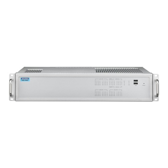
Overview The following two figures show the indicators and connectors on UNO-4673A/4683 series. The following sections give you detailed information about function of each peripheral. Figure 2.1 UNO-4673A Front Panel Figure 2.2 UNO-4673A Rear Panel Figure 2.3 UNO-4673ADP Front Panel Figure 2.4 UNO-4673ADP Rear Panel UNO-4673A/4683 Series User Manual... - Page 19 Figure 2.5 UNO-4683 Front Panel Figure 2.6 UNO-4683 Rear Panel Figure 2.7 UNO-4683DP Front Panel Figure 2.8 UNO-4683DP Rear Panel UNO-4673A/4683 Series User Manual...
-
Page 20: Led Indicators
LED Indicators The LEDs in the front panel can be divided into 4 groups 2.2.1 System Status Indicators Table 2.1: Definition of System Status Indicators Item Status Description Green System power is on System power is off Data being received/ transmitted between on CF/ Green SATA No Data being received/ transmitted on CF/SATA... -
Page 21: Lan Status Indicators
2.2.2 LAN Status Indicators: Table 2.2: Definition of LAN Status Indicators Item Status Description Green 1Gbps network link LAN/Link (Port Orange 100Mbps network link 1~2) 10Mbps network link or invalid network link Orange 100Mbps network link LAN/Link (Port 3~6) 10Mbps network link or invalid network link Green Ethernet date being received/ transmitted LAN/Active... -
Page 22: Indicators For Expansion Slots
2.2.4 Indicators for Expansion Slots These LED indicators are defined by the UNOP series expansion modules, please refer to the related document for the definition. Power Input The UNO-4673A/4683 series support AC/DC power input to fulfill the need of field site. - Page 23 The UNO-4673ADP/4683DP support redundant AC/DC power input to fulfill the need of field site. The specification of the power input, please refer to Table 2.4. The function of each part is described as below: Table 2.6: Dual AC/DC Power Input Function Introduction Item Function Description Screw terminal for AC/DC power 1 input...
-
Page 24: Specification Of The Relay
The UNO-4673ADC/4683DC support redundant 48 VDC power input to fulfill the need of field site. The specification of the power input, please refer to Table 2.7. The function of each part is described as below: Table 2.9: 48VDC Dual Power Input Function Introduction Item Function Description Screw terminal for 48VDC power 1 input... -
Page 25: Wiring Diagram Of The Relay
Win- dows Device Manager easily. 2.4.1 OXuPCI952 UARTs with 128 bytes FIFO Advantech UNO-4673A/4683 series comes with Oxford OXuPCI952 UARTs contain- ing 128 bytes FIFOs. 2.4.2 RS-422/485 Detection In RS-422/485 mode, UNO-4673A/4683 series automatically detects signals to match RS-422 or RS-485 networks. -
Page 26: Terminal Resistor (Sw6,Sw8)
2.4.4 Terminal Resistor (SW6,SW8) The onboard termination resistor (120 ohm) for COM1, COM2 can be used for long distance transmission or device matching. (Default Open.) Please also refer to Table 2.9 for the mapping table of Jumper and COM port. Table 2.10: Jumper setting of terminal resistor Status Description... -
Page 27: Rs-485 Auto Flow & Rs-422 Master/Slave Modes
2.4.6 RS-485 Auto Flow & RS-422 Master/Slave Modes You can set the “Auto Flow Control” mode of RS-485 or “Master/Slave” mode of RS- 422 by using the SW3 DIP switch for COM1, COM2. Please also refer to Table 2.9 for the COM port mapping with the DIP. -
Page 28: Dvi-I Display
It integrates both analog and digital video signal. This supports high- speed, high-resolution digital display and traditional analog display. You could link your DVI or VGA monitor through a DVI-I to DVI and VGA cable (Advantech P/N: 1700004713). For a detailed DVI-I pin assignment, please refer to A.4. -
Page 29: Advanced Watchdog Timer
3rd party plug-in card which is with high power consumption or bad power efficiency. It is not recommended to use this kind of card in the embedded sys- tem, only while the plug-in card is mandatory, please contact Advantech for this optional support. - Page 30 UNO-4673A/4683 Series User Manual...
-
Page 31: Initial Setup
Chapter Initial Setup... -
Page 32: Configuration
Configuration To open the chassis, please follow the steps below: Remove all power and signal connections Place the unit with the heat-sink side down Remove the plug-in module in the slot 3 Remove the screws on the cover Install a Well-configured CompactFlash Card in this area Install a USB device in this area Refer to this manual to configure the COM ports Figure 3.1 Location for Configuration... -
Page 33: Install A Usb Dongle
Install a USB Dongle UNO-4673A/4683 series provides a clamp to fix the USB dongle which can be installed inside the chassis. Please follow the steps to install the USB dongle and clamp: Please follow 3.1 to open the cover for configuration. Plug the USB Dongle in the upside port, please note the downside port is a dummy port. -
Page 34: Install A Hard Disk
Install a Hard Disk Please follow the steps below to install an HDD: Turn the heat-sink side down. Unscrew the screws and get the HDD bay apart. Insert the HDD into the HDD bay and screw it. UNO-4673A/4683 Series User Manual... -
Page 35: Installing In A Rack
Connect the SATA cable between HDD and connector then assemble the HDD back to the chassis. The locations of the connectors are below HDD Bay. SATA 0 SATA 1 Figure 3.2 Location of SATA connections Installing in a Rack UNO-4673A/4683 series provides the kits for Rack mounting in the accessory box Please screw the ears and handles at the position indicated below. -
Page 36: Bios Setup And System Assignments
2U (88.9mm) space height on the top of the unit. BIOS Setup and System Assignments UNO-4673A/4683 series adopts Advantech's SOM-5788 CPU module. While UNO- 4673A series adopts Advantech's SOM-6763 CPU module. Further information about the SOM module, can be found in SOM's user's manual. -
Page 37: System Settings & Pin Assignments
Appendix System Settings & Pin Assignments... -
Page 38: System I/O Address & Interrupt Assignments
System I/O Address & Interrupt Assignments Table A.1: UNO-4673A/4683 Series System I/O Ports Address Range Device 000-01F DMA controller (slave) 020-03F Interrupt controller 1, (master) 040-05F 8254 timer/counter 060-06F 8042 (keyboard controller) 070-07F Real-time clock, non-maskable interrupt (NMI)mask 080-09F DMA page register, 0A0-0BF Interrupt controller 2 (slave) 0C0-0DF... -
Page 39: Rs-232/422/485 Serial Ports (Com1~Com2)
RS-232/422/485 Serial Ports (COM1~COM2) Table A.3: COM1~2 Port Pin Definitions RS-232 Table A.4: RS-232 Serial Ports COM1~2 RS-232 RS-422 RS-485 DATA- DATA+ USB Connectors Table A.5: USB Connector Pin Assignments Signal Cable Color DATA- White DATA+ Green Black UNO-4673A/4683 Series User Manual... -
Page 40: Dvi-I Connector (Uno-4683 Series)
DVI-I Connector (UNO-4683 Series) Table A.6: DVI Connector Pin Assignments Signal Name TMDS_C2# TMDS_C2 CRT_DDC_CLK CRT_DDC_DATA MDVI_CLK MDVI_DATA VGAVSY TMDS_C1# TMDS_C1 VCC_DVI VGA Detect HP_DET TMDS_C0# TMDS_C0 TMDS_CK# TMDS_CK VGAR VGAG VGAB VGAHSY UNO-4673A/4683 Series User Manual... -
Page 41: Vga Display Connector (Uno-4673A Series)
VGA Display Connector (UNO-4673A series) Table A.7: VGA Adaptor Cable Pin Assignments Signal Name Green Blue H-SYNC V-SYNC SATA Hard Drive RAID Support (UNO-4683 Series) In order to install an operating system onto a RAID volume, the RAID option must be... -
Page 42: Create A Raid Volume
A.6.2 Create a RAID Volume Use the following steps to create a RAID volume. When the Intel Rapid Storage Technology option ROM status screen appears during POST, press Ctrl and i at the same time to enter the option ROM user interface. - Page 43 Unless you have selected RAID 1, use the up or down arrow keys to select the strip size and press Enter. Press Enter to select the physical disks. Select the appropriate number of hard drives by using the up or down arrow keys to scroll through the list of hard drives and press Space to select the drive.
-
Page 44: Install The Raid Driver Using The F6 Installation Method
A.6.3 Install the RAID Driver Using the F6 Installation Method Perform the following steps to install the Intel Rapid Storage Technology driver during operating system setup: Press F6 when you see a message in the status line that says, Press F6 if you need to install a third party SCSI or RAID driver. - Page 45 When you see a prompt that says, Please insert the disk labeled Manufacturer- supplied hardware support disk into Drive A:, insert ;a floppy disk containing the following files: IAAHCI.INF, IAAHCI.CAT, IASTOR.INF, IASTOR.CAT, IAS- TOR.SYS, and TXTSETUP.OEM. Note! Use the Floppy Configuration Utility to create a floppy disk with the nec- essary files or copy required file from driver folder.
- Page 46 During Windows setup, create a partition and file system on the RAID volume as you would on any physical disk. Note! If you wish to use the Intel Rapid Storage Technology user interface in Windows, you will need to install Intel Rapid Storage Technology by run- ning the Setup.exe process after these steps have been completed and the operating system has been successfully installed.
-
Page 47: Appendix B Watchdog Timer Register
Appendix Watchdog Timer Register... -
Page 48: Watchdog Timer Register
Watchdog Timer Register B.1.1 Register 1: WatchDog Timer Load (WDTLOAD) OFFSET = 0x000 WDTLOAD serves as a countdown timer. Once an 8-bit width value is loaded into the register, it starts to count down to zero automatically. Table B.1: WDTLOAD Bits Definitions 31 30 29 28 27 26 25 24 23 22 21 20 19 18 17 16 15 14 13 12 11 10 9 8 7 6 5 4 3 2 1 0 User Settings... -
Page 49: Register 3: Watchdog Timer Control (Wdtctl)
B.1.3 Register 3: WatchDog Timer Control (WDTCTL) OFFSET = 0x008 WDTCTL selects the corresponding event as time out. It could be configured to choose reset, interrupt or digital output signal when time out. 31 30 29 28 27 26 25 24 23 22 21 20 19 18 17 16 15 14 13 12 11 10 9 8 7 6 5 4 3 2 1 0 User Settings Reserved... -
Page 50: Register 5: Watchdog Timer Time-Out Trigger Status (Wdttr)
B.1.5 Register 5: WatchDog Timer Time-Out Trigger Status (WDTTR) OFFSET = 0x010 WDTTR saves the occurrence times of watchdog timer time-out. The corresponding operation differs from the access type which is taken on WDTTR. A read-out from WDTTR would clear the watchdog interrupt while a write-in clear WDTTR. 31 30 29 28 27 26 25 24 23 22 21 20 19 18 17 16 15 14 13 12 11 10 9 8 7 6 5 4 3 2 1 0 User Settings... -
Page 51: Register 7: Watchdog Timer Reset Control Register (Wdtrstctr)
B.1.7 Register 7: WatchDog Timer Reset Control Register (WDTRSTCTR) OFFSET = 0x018 Based on the watchdog timer time-out frequency which is stored in WDTTR, WDTINTCTR sets the period of reset. WDTTR plus one as watchdog timer time out occurred. While the number of occurrences exceeds the value saved in WDTINTCTR, a reset signal would be issued. - Page 52 B.1.9 Register 9:WatchDog Timer Interrupt (WDTINT) OFFSET = 0x020 WDTINT is a register indicating whether interrupt is triggered. Once read out the value in WDTINT, it'll be cleared immediately to avoid looping. 31 30 29 28 27 26 25 24 23 22 21 20 19 18 17 16 15 14 13 12 11 10 9 8 7 6 5 4 3 2 1 0 User Settings Reserved...
- Page 53 UNO-4673A/4683 Series User Manual...
- Page 54 No part of this publication may be reproduced in any form or by any means, electronic, photocopying, recording or otherwise, without prior written permis- sion of the publisher. All brand and product names are trademarks or registered trademarks of their respective companies. © Advantech Co., Ltd. 2012...
Need help?
Do you have a question about the UNO-4673A Series and is the answer not in the manual?
Questions and answers