
Related Manuals for Advantech UNO-2174A


Summary of Contents for Advantech UNO-2174A
-
Page 1: User Manual
UNO-2174A/2178A Automation Computers with Intel® Atom™ Processors, 6 x USB, 8 x COM, 2 x Mini-PCIe User Manual... - Page 2 C&T is a trademark of Chips and Technologies, Inc. All other product names or trademarks are properties of their respective owners. Support For more information on this and other Advantech products, please visit our websites at: http://www.advantech.com For technical support and service, please visit our support website at: http://www.advantech.com/support/...
-
Page 3: Product Warranty
Product Warranty Advantech warrants to you, the original purchaser, that each of its prod- ucts will be free from defects in materials and workmanship for one year from the date of purchase. This warranty does not apply to any products that have been repaired or... -
Page 4: Declaration Of Conformity
This product has passed the CE test for environmental specifications when shielded cables are used for external wiring. We recommend the use of shielded cables. This kind of cable is available from Advantech. Please contact your local supplier for ordering information. - Page 5 Safety Instructions Read these safety instructions carefully. Keep this User Manual for later reference. Disconnect this equipment from any AC outlet before cleaning. Use a damp cloth. Do not use liquid or spray detergents for cleaning. For plug-in equipment, the power outlet socket must be located near the equipment and must be easily accessible.
- Page 6 The sound pressure level at the operator's position according to IEC 704-1:1982 is no more than 70 dB (A). DISCLAIMER: This set of instructions is given according to IEC 704-1. Advantech disclaims all responsibility for the accuracy of any statements contained herein. UNO-2174A/2178A User Manual...
-
Page 7: Table Of Contents
Accessories................ 7 Chapter 2 Hardware Functionality ........10 Introduction ..............10 Figure 2.1:Front Panel of UNO-2174A ......10 Figure 2.2:Front Panel of UNO-2178A ......10 Figure 2.3:Rear Panel of UNO-2174A ......10 Figure 2.4:Rear Panel of UNO-2178A ......10 UNO-2174A/2178A Interface (COM1~COM6)..... 11 RS-232/422/485 Interface (COM A ~ B)...... - Page 8 PS/2 Keyboard and Mouse Connector ......34 USB Connector ............... 34 VGA Display Connector ..........35 A.10 Clear CMOS (JP2) ............36 Table A.10:JP2 Clear CMOS........36 A.11 System Power AT or ATX Selection (JP1)..... 36 Table A.11:AT/ATX Selection........36 UNO-2174A/2178A User Manual viii...
- Page 9 Overview This chapter provides an overview of UNO-2174A/2178A’s specifications. Sections include: • Introduction • Hardware specification • Safety precautions • Chassis dimensions...
-
Page 10: Chapter 1 Overview
UNO-2174A/2178A is an embedded Application Ready Platform (ARP) that can shorten your development time and offers rich networking inter- faces to fulfill extensive needs in different projects. UNO-2174A and UNO-2178A include Intel’s latest Atom technology and provide rich interfaces including up to 4 serial ports, 2 x GbE Lan, 6 x USB ports and Audio. -
Page 11: Hardware Specifications
CF: 1 x front-accessible type I/II CF slot HDD: 1 x built-in 2.5" SATA HDD/SSD bracket • Display DB 15 VGA connector, UNO-2174A support up to 1400 x 1050, UNO-2178A supports up to 2048 x 1536 • Watchdog Timer Programmable 256 levels timer interval,... - Page 12 HDD: 1 Grms @ 5 ~ 500 Hz Reserved Functions • Digital Input/Output: 4 x DI and 4 x DO pin head* *Note: This function is reserved for projects Expansion Board (Additional Purchase Required) • PC/104+ 1 x PC/104+ (5V, 3A or 3.3V, 3A) UNO-2174A/2178A User Manual...
-
Page 13: Safety Precautions
Caution! Always ground yourself to remove any static electric charge before touching UNO-2174A/ 2178A. Modern electronic devices are very sen- sitive to static electric charges. Use a grounding wrist strap at all times. Place all electronic com- ponents on a static-dissipative surface or in a static-shielded bag. -
Page 14: Chassis Dimensions
1.4 Chassis Dimensions 227.80 254.80 Figure 1.1: UNO-2174A Chassis Dimensions 227.80 254.80 Figure 1.2: UNO-2178A Chassis Dimensions UNO-2174A/2178A User Manual... -
Page 15: Accessories
1.5 Accessories Please refer below for the accessory list: • 3-pin connector for power wiring (Advantech P/N : 1652003206) • SATA signal cable (Advantech P/N : 1700006812) • SATA power cable (Advantech P/N : 1700004712) • 8 PCS jumper (Advantech P/N : 1653302122) •... - Page 16 UNO-2174A/2178A User Manual...
- Page 17 Hardware Functionality This chapter shows how to setup the UNO-2174A/2178A’s hardware func- tions, including connecting peripherals, setting switches and indicators. Sections include: • Peripherals • RS-232 Interface • RS-422/485 Interface • LAN / Ethernet Connector • Power Connector • PS/2 Mouse and Keyboard Connector •...
-
Page 18: Chapter 2 Hardware Functionality
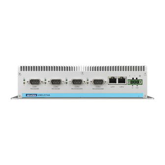
Chapter 2 Hardware Functionality 2.1 Introduction The following figures show the connectors on UNO-2174A/2178A. The following sections give you information about each peripheral. Figure 2.1: Front Panel of UNO-2174A Figure 2.2: Front Panel of UNO-2178A Figure 2.3: Rear Panel of UNO-2174A Figure 2.4: Rear Panel of UNO-2178A... -
Page 19: Uno-2174A/2178A Interface (Com1~Com6)
The default setting of COMA and COMB are RS- 422/485. Please note COM A/B in Microsoft Windows is showed as COM3,4 (UNO-2174A) or COM7,8 (UNO-2178A) in the device man- ager after driver is installed. Note: In S1 mode, COM A, B data re-transmission will not function prop- erly and may include error signals after wake up. -
Page 20: 16C550 Uarts With 128-Byte Standard
RS-422 or RS-485 networks. (No jumper change required) 2.3.3 Automatic Data Flow Control Function for RS-485 In RS-485 mode, UNO-2174A/2178A automatically detects the direction of incoming data and switches its transmission direction accordingly. So no handshaking signal (e.g. RTS signal) is necessary. This lets you conve- niently build an RS-485 network with just two wires. -
Page 21: Terminal Resistor Setup For Rs-422/485
2.4 Terminal Resistor Setup for RS-422/485 The onboard termination resistor (120 Ohm) for COM1-6, COM A, and COM B can be used for long distance transmission or device match- ing (Default Open). Each terminal resistor responds to different channels for RS-422/485. Usually, these resistors are needed for both ends of the communication wires and the value of the resistors should match the characteristic imped- ance of the wires used. -
Page 22: Rs-232/422/485 Selection
RS-232/422/485 selection are JCOM A and JCOM B. 2.5.1 COM1 - 6 Jumper Setting for RS-232 Interface (default) Figure 2.5: RS-232 Jumper Setting (COM1,2) Figure 2.6: RS-232 Jumper Setting (COM3-6) Jumper Setting for RS-485 Interface Figure 2.7: RS-485 Jumper Setting (COM1,2) UNO-2174A/2178A User Manual... -
Page 23: Com A And Com B
Figure 2.8: RS-485 Jumper Setting (COM3-6) 2.5.2 COM A and COM B Jumper Setting for RS-422/485 Interface (default) Jumper Setting for RS-232 Interface Chapter 2... -
Page 24: Rs-485 Auto Flow & Rs-422 Master/Slave Mode
COM B RS-485: N/A 2.6 LAN: Ethernet Connector UNO-2174A/2178A is equipped with two Gigabit LAN controllers. The controller chip used in both model is RTL8111C Ethernet controller that is fully compliant with IEEE 802.3u 10/100Base-T CSMA/CD standards and IEEE 802.3ab specification for 1000Mbps Ethernet. The Ethernet port provides a standard RJ-45 jack on board, and LED indicators on the front side to show its Link (Green LED) and Active (Yellow LED) status. -
Page 25: Power Connector
You can now write software applications without being concerned that system crashes will erase criti- cal data from the memory. Please contact Advantech if this is function is required in your project. -
Page 26: Rtc Battery Specification
2.12 RTC Battery Specification UNO-2174A/2178A has RTC Battery to ensure the setting in bios and system clock can be kept, even with power disconnected for a short time. • Type: BR2032 (Using CR2032 is NOT recommended) • Output Voltage: 3 V •... -
Page 27: Reset Button
Press the "Reset" button to activate the hardware reset function. 2.15 HD Audio UNO-2174A/2178A is equipped with ALC892-GR which is a High Defi- nition Audio Codec. UNO-2174A/2178AF provides 3 phone jack con- nector for 5.1 channel output. Please configure the function through provided software utility. - Page 28 UNO-2174A/2178A User Manual...
- Page 29 Initial Setup This chapter introduces how to initial- ize the UNO-2174A/2178A. Sections include: • Inserting a CompactFlash Card • Chassis Grounding • Conneting Power • Connecting a Hard Disk • BIOS Setup and System Assignments...
-
Page 30: Chapter 3 Initial Setup
"Integrated Peripherals > IDE Device Setup > IDE Configuration > Enhanced Mode" 3.2 Chassis Grounding UNO-2174A/2178A provides good EMI protection and a stable ground- ing base. There is an easy-to-connect chassis grounding point to use. Figure 3.1: Chassis Grounding Connection... -
Page 31: Connecting Power
3.4 Installing a Hard Disk The procedure for installing a hard disk into the UNO-2174A/2178A is below. Please follow these steps carefully. Please note the system is not compatible with +12V HDD. Please use an HDD with lower power input. -
Page 32: Installing A Wireless Lan Card And Antenna
3.5 Installing a Wireless LAN Card and Antenna Please contact Advantech to prepare the following optional kit: Rear Panel for Antenna • The internal cable : 1700001854 (11cm) Wireless Module ( PCI Express mini card ) • One of the suggested module is 968EMW0021 which is a verified Wireless IEEE 802.11b/g/n module... -
Page 33: Bios Setup
Press "DEL" in the boot-up screen to enter the BIOS setup utility. Please follow the instruction on the screen to do the necessary settings. Please note that you can try to “Load Optimized Defaults” from the BIOS Setup manual if the UNO-2174A/2178A does not work properly. Chapter 3... - Page 34 UNO-2174A/2178A User Manual...
- Page 35 System Settings and Pin Assignments...
-
Page 36: Appendix A System Settings And Pin Assignments
Appendix A System Settings and Pin Assignments A.1 System I/O Address and Interrupt Assignment Table A.1: UNO-2174A/2178A Interrupt Assignments Interrupt No. Interrupt Source Parity Error Detected IRQ 0 Interval timer IRQ 1 Keyboard IRQ 2 Interrupt from controller 2 (cascade) -
Page 37: Board Connectors And Jumpers
A.2 Board Connectors and Jumpers There are several connectors and jumpers on the UNO-2174A/2178A board. The following sections tell you how to configure the UNO-2174A/ 2178A hardware setting. Figure A-1 shows the locations of UNO-2174A/ 2178A’s connectors and jumpers. Figure A.1: Connector & Jumper Locations (front) - Page 38 Table A.2: UNO-2174A/2178A Connectors and Jumpers Label Function Fuse for input DC power CN26 PCI Express mini Card Socket CN32 CN33 SATA signal connector CN34 SATA power connector SW11 Switch for terminal resistor of COM1, 2 SW10 Switch for terminal resistor of COM A...
-
Page 39: Rs-232/485 Standard Serial Port (Com1~Com2)
A.3 RS-232/485 Standard Serial Port (COM1~COM2) Table A.3: RS-232 Standard Serial Port Pin Assignments RS-232 Signal Name RS-485 Signal Name DATA- DATA+ Appendix A... -
Page 40: Rs-232/485 Serial Port (Com3-Com6)
A.4 RS-232/485 Serial Port (COM3-COM6) This function is enabled through expansion cable (UNO-2178A only). Table A.4: RS-232/485 Serial Port Pin Assignments RS-232 Signal Name RS-485 Signal Name Data- Data+ UNO-2174A/2178A User Manual... -
Page 41: Rs-232/422/485 Serial Port (Com A ~ Com B)
A.5 RS-232/422/485 Serial Port (COM A ~ COM B) Table A.5: RS-232/422/485 Serial Port Pin Assignments RS-232 RS-422 RS-485 Data- Data+ A.6 Power Connector (PWR) Table A.6: Power connector pin assignments V+ (9~36V Field Ground Appendix A... -
Page 42: Ps/2 Keyboard And Mouse Connector
A.7 PS/2 Keyboard and Mouse Connector Table A.7: Keyboard and Mouse connector pin assignments Signal Name KB DATA MS DATA KB Clock MS Clock A.8 USB Connector Table A.8: USB connector pin assignments Signal Name Cable Color DATA- White DATA+ Green Black UNO-2174A/2178A User Manual... -
Page 43: Vga Display Connector
A.9 VGA Display Connector Table A.9: VGA adaptor cable pin assignment Signal Name Green Blue H-SYNC V-SYNC Appendix A... -
Page 44: Clear Cmos (Jp2)
Table A.10: JP2 Clear CMOS Configuration Function Clear CMOS Normal ( Default) A.11 System Power AT or ATX Selection (JP1) UNO-2174A/2178A can set AT or ATX power mode in the bios or hard- ware jumper setting. Table A.11: AT/ATX Selection Configuration Function AT mode...
Need help?
Do you have a question about the UNO-2174A and is the answer not in the manual?
Questions and answers