
Related Manuals for Advantech UNO-2483G


Summary of Contents for Advantech UNO-2483G
- Page 1 User Manual UNO-2483G UNO-2473G Intel® Core™ i7/i3/Celeron/Atom Regular-Size Automation Computer w/ 4/2 x GbE 3/1 x mPCIe, HDMI/VGA...
- Page 2 No part of this manual may be reproduced, copied, translated or transmitted in any form or by any means without the prior written permission of Advantech Co., Ltd. Information provided in this manual is intended to be accurate and reliable. How- ever, Advantech Co., Ltd.
-
Page 3: Declaration Of Conformity
Because of Advantech’s high quality-control standards and rigorous testing, most of our customers never need to use our repair service. If an Advantech product is defec- tive, it will be repaired or replaced at no charge during the warranty period. For out- of-warranty repairs, you will be billed according to the cost of replacement materials, service time and freight. -
Page 4: Technical Support And Assistance
這是甲類測試產品,在居住的環境中使用時,可能會造成射頻干擾,在這種情況下, 使用者會被要求採取某些適當的對策 Technical Support and Assistance Visit the Advantech web site at www.advantech.com/support where you can find the latest information about the product. Contact your distributor, sales representative, or Advantech's customer service center for technical support if you need additional assistance. Please have the following information ready before you call: –... -
Page 5: Safety Instructions
The sound pressure level at the operator's position according to IEC 704-1:1982 is no more than 70 dB (A). DISCLAIMER: This set of instructions is given according to IEC 704-1. Advantech disclaims all responsibility for the accuracy of any statements contained herein. - Page 6 UNO-2483G/2473G User Manual...
-
Page 7: Table Of Contents
Chapter Hardware Functionality .......5 Introduction ....................6 Figure 2.1 Front Panel of UNO-2483G ........6 Figure 2.2 Rear Panel of UNO-2483G/UNO-2473G-E3AE ..6 Figure 2.3 Front Panel of UNO-2473G-J3AE ......6 Figure 2.4 Rear Panel of UNO-2473G-J3AE....... 6 UNO-2483G/UNO-2473G Interface (COM1~COM4) ........ 7 2.2.1... - Page 8 Board Connectors and Jumpers ............. 25 Figure A.1 UNO-2483G Connector & Jumper Locations (front) 25 Table A.2: Connectors and Jumpers ......... 25 Figure A.2 UNO-2473G Connector & Jumper Locations (front) 26 Connectors and Jumpers................ 26 Table A.3: Connectors and Jumpers ......... 26 RS-232 Standard Serial Port ..............
-
Page 9: Chapter 1 Overview
Chapter Overview This chapter provides an overview of UNO-2483G/UNO-2473G speci- fications. Sections include: Introduction Safety Precautions Accessories Optional Accessories Hardware Specifications... -
Page 10: Introduction
UNO-2483G/UNO-2473G includes Intel’s latest Core i7/i3/Celeron/Atom technology and provide rich interfaces including up to 4 serial ports, 4 x GbE LAN, 4 x USB ports and Audio. UNO-2483G/ UNO-2473G supports two display types, VGA and HDMI for various high resolution requirements and also Advantech latest iDoor technology. -
Page 11: Accessories
UNO-2473G-E3AE: 28W (Typical), 48W (Max) – UNO-2473G-J3AE: 10W (Typical), 14W(Max) CPU: – UNO-2483G-474AE: 4th Gen Intel® Core™ i7-4650U ULT 1.7 GHz Dual Core, 4MB L2 – UNO-2483G-434AE: 4th Gen Intel® Core™ i3-4010U ULT 1.7 GHz Dual Core, 3MB L2 –... - Page 12 Applicable Models: – UNO-2483G-4C3AEIntel® Celeron® 2980U ULT 1.6GHz, 4GB, 4 x LANs, 2 x mPCIe – UNO-2483G-434AEIntel® Core™ i3-4010U ULT 1.7GHz, 8GB, 4 x LANs, 2 x mPCIe – UNO-2483G-474AEIntel® Core™ i7-4650U ULT 1.7GHz, 8GB, 4 x LANs, 2 x mPCIe –...
-
Page 13: Chapter 2 Hardware Functionality
Chapter Hardware Functionality This chapter shows how to setup the UNO-2483G/UNO-2473G’s hardware functions, including connecting peripherals, setting switches and indicators. Sections include: Introduction RS-232 Interface RS-422/485 Interface LAN / Ethernet Connector Power Connector Audio Connector ... -
Page 14: Introduction
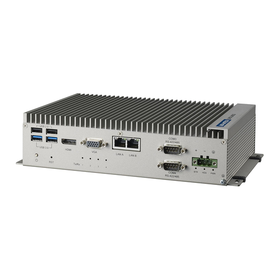
Introduction The following figures show the connectors on UNO-2483G/UNO-2473G. The follow- ing sections give you information about each peripheral. Figure 2.1 Front Panel of UNO-2483G Figure 2.2 Rear Panel of UNO-2483G/UNO-2473G-E3AE Figure 2.3 Front Panel of UNO-2473G-J3AE Figure 2.4 Rear Panel of UNO-2473G-J3AE... -
Page 15: Uno-2483G/Uno-2473G Interface (Com1~Com4)
UNO-2483G/UNO-2473G Interface (COM1~COM4) UNO-2483G/UNO-2473G offers two standard RS-232 and two RS-422/485 (with cable) serial communication inter-face ports: COM1 ~ COM4. The IRQ and I/O address range of COM1 to COM4 are listed below: COM1: 3F8h, IRQ4 COM2: 2F8h, IRQ3 COM3: 3E8h, IRQ10... -
Page 16: Lan: Ethernet Connector
& Play and hot swapping for up to 127 external devices. Two of the four connectors on UNO-2483G and one of the four connector on UNO-2473G are USB 3.0 standard. The USB interface complies with USB EHCI, Rev. 2.0 compliant. The USB interface can be disabled in the system BIOS setup. -
Page 17: Rtc Battery Specification
RTC Battery Specification The UNO-2483G/UNO-2473G has an RTC Battery to ensure the setting in BIOS and system clock can be kept, even with power disconnected for a short time. Type: BR2032 (Using CR2032 is NOT recommended) Output Voltage: 3 V Location: BH1, please refer to below figure ... -
Page 18: Hd Audio
2.11 PCI Express Mini Card Socket The UNO-2483G supports two sockets for full size PCI Express mini cards. The first interface (CN14 on the left) is the default defined ONLY for mSATA storage.The sec- ond interface (CN31) is the half size PCI Express mini card.The third and fourth... -
Page 19: Figure 2.7 Uno-2473G-E3Ae Mpcie Location
COM port, Profibus, WLAN GPRS, 3G, mRAM and iDoor Module. Users can install the card easily using the optional kit, please refer to Chapter 3.5 for details. Figure 2.8 UNO-2473G-J3AE mPCIe Location UNO-2483G/2473G User Manual... - Page 20 UNO-2483G/2473G User Manual...
-
Page 21: Chapter 3 Initial Setup
Chapter Initial Setup This chapter introduces how to initialize the UNO-2483G/UNO- 2473G. Sections include: Inserting a mSATA Chassis Grounding Connecting Power Connecting a Hard Disk BIOS Setup and System Assignments... -
Page 22: Inserting A Msata
Screw the two screws on board to fix mSATA. Screw back the bottom cover. Chassis Grounding UNO-2483G/2473G provides good EMI protection and a stable grounding base. There is an easy-to-connect chassis grounding point to use. Figure 3.1 Chassis Grounding Connection... -
Page 23: Installing A Hard Disk
Installing a Hard Disk The procedure for installing a hard disk into the UNO-2483G/UNO-2473G is below. Please follow these steps carefully. Please note the system is not compatible with +12V HDD. Please use a HDD with lower power input. Remove the power cord. -
Page 24: Installing A Wireless Lan Card And Antenna
Installing a Wireless LAN Card and Antenna Please contact Advantech to prepare the following optional kit: Rear Panel for Antenna The internal cable: 1750006043 (15cm) Wireless Module (PCI Express mini card) One of the suggested module is EWM-W151H01E which is a verified Wireless IEEE 802.11b/g/n module... -
Page 25: Figure 3.2 Uno-2483G
Remove the hole(s) on the rear panel for antenna installation. Install the internal cable 1750006043 (15cm) on the rear panel. Plug the Wireless module with bracket kit (9656EWMG00E) onto the PCI Express mini card socket. Figure 3.2 UNO-2483G Figure 3.3 UNO-2473G UNO-2483G/2473G User Manual... -
Page 26: Bios Setup
Press “F2” in the boot-up screen to enter the BIOS setup utility. Please follow the instruction on the screen to do the necessary settings. Please note that you can try to “Load Optimized Defaults” from the BIOS Setup man- ual if the UNO-2483G/UNO-2473G does not work properly. AMT Configuration ... - Page 27 This item allows users to enable or disable WatchDog Timer. OS Timer Sets OS Watchdog Timer. BIOS Timer Sets BIOS Watchdog timer. TPM Support This item allows users to enable or disable Trusted Platform Module function. UNO-2483G/2473G User Manual...
-
Page 28: Teaming Configuration
Please install the OS and LAN driver first. After entering the OS, please right click the mouse on Network adaptors to con- figure the Network Connection properties in the device manager. Set Teaming with other adapters in Teaming and then press New Team. UNO-2483G/2473G User Manual... - Page 29 Select the adapters to include in this team then press Next. Specify the name for the team then press Next. Select a team mode. Here Adaptive Load Balancing is chosen. UNO-2483G/2473G User Manual...
-
Page 30: Enabling Raid In Bios
Select the Advanced menu, then the SATA Configuration menu. Set the SATA Mode Select option to RAID. Press the F10 key to save the BIOS settings and exit the BIOS Setup program. Note! The UNO-2473G only has ONE HDD/SSD SATA slot. UNO-2483G/2473G User Manual... -
Page 31: System Settings And Pin Assignments
Appendix System Settings and Pin Assignments... -
Page 32: System I/O Address And Interrupt Assignment
Communications Port (COM2) IRQ4 Communications Port (COM1) IRQ5 Communications Port (COM4) IRQ6 Available IRQ8 System CMOS/Real-time clock IRQ9 Microsoft ACPI-Compliant System IRQ10 Communications Port (COM3) IRQ12 PS/2 Compatible Mouse IRQ13 Numeric data processor IRQ14 Reserved IRQ15 Reserved UNO-2483G/2473G User Manual... -
Page 33: Board Connectors And Jumpers
Board Connectors and Jumpers There are several connectors and jumpers on the UNO-2483G/UNO-2473G board. The following sections tell you how to configure the UNO-2483G/UNO-2473G hard- ware setting. Figure A.1 shows the locations of the connectors and jumpers. Figure A.1 UNO-2483G Connector & Jumper Locations (front) Table A.2: Connectors and Jumpers... -
Page 34: Connectors And Jumpers
Connectors and Jumpers Table A.3: Connectors and Jumpers Label Function CN14 CN15 PCI Express Mini Card Socket USB Pin Headers Battery for RTC CN29 ON/OFF/RESET Switch CN11 COM3, COM4 Turn On/Off Termination Resistors for COM3/COM4 No Function UNO-2483G/2473G User Manual... -
Page 35: Rs-232 Standard Serial Port
RS-232 Standard Serial Port Table A.4: RS-232 Serial Port Pin Assignments Pin Name RS-422/485 Serial Port Table A.5: RS-422/485 Serial Port Pin Assignments RS-422 RS-485 Data- Data+ UNO-2483G/2473G User Manual... -
Page 36: Power Connector (Pwr)
Power Connector (PWR) Table A.6: Power connector pin assignments V+ (24VDC) Field Ground UNO-2483G/2473G User Manual... -
Page 37: Usb Connector
Black Table A.8: USB 3.0 Connector Pin Assignments Signal Name Description VBUS Power USB2.0 differential pair Ground for power return StdA_SSRX- SuperSpeed receiver differential pair StdA_SSRX+ GND_DRIAN Ground for signal return StdA_SSTX- SuperSpeed transmitter differential pair StdA_SSTX+ UNO-2483G/2473G User Manual... -
Page 38: Hdmi Display Connector
TMDS Data2 Shield TMDS Data2- TMDS Data1+ TMDS Data1 Shield TMDS Data1- TMDS Data0+ TMDS Data0 Shield TMDS Data0- TMDS Clock+ TMDS Clock Shield TMDS Clock- Reserved DDC/CEC/HEC Ground +5 V Power (max 50 mA) Hot Plug Detect UNO-2483G/2473G User Manual... -
Page 39: Turn On/Off Termination Resistors (120 Ohm) For Com3/Com4 (Sw1)
Turn On/Off Termination Resistors (120 ohm) for COM3/COM4 (SW1) Enable Termination Resistors COM3: Jumper (3-4) On COM4: Jumper (5-6) On Disable Termination Resistors COM3: Jumper (3-4) Off COM4: Jumper (5-6) Off UNO-2483G/2473G User Manual... - Page 40 No part of this publication may be reproduced in any form or by any means, electronic, photocopying, recording or otherwise, without prior written permis- sion of the publisher. All brand and product names are trademarks or registered trademarks of their respective companies. © Advantech Co., Ltd. 2016...
Need help?
Do you have a question about the UNO-2483G and is the answer not in the manual?
Questions and answers