
Related Manuals for Advantech UNO-2372G-J1 Series


Summary of Contents for Advantech UNO-2372G-J1 Series
- Page 1 User Manual UNO-2372G-J1 電腦 Intel® Celeron® J3455 Small Form Factor Modular Box Platform with 2x GbE, 4x USB, 4x COM, 2x mPCIe, HDMI, and DP...
- Page 2 The documentation and the software included with this product are copyrighted 2020 by Advantech Co., Ltd. All rights are reserved. Advantech Co., Ltd. reserves the right to improve the products described in this manual at any time without notice. No part of this manual may be reproduced, copied, translated, or transmitted in any form or by any means without the prior written permission of Advantech Co., Ltd.
- Page 3 限用物質含有情況標示聲明書 Declaration of the Presence Condition of the Restricted Substances Marking 設備名稱:電腦 型號 ( 型式 ):UNO-2372G-J1( 系列型號請參見次頁說明書 ) UNO2372GJ1 Equipment name Type designation (Type) 限用物質及其化學符號 Restricted substances and its chemical symbols 單元 鉛 汞 鎘 六價鉻 多溴聯苯 多溴二苯醚 Unit Lead Mercury Cadmium Hexavalent...
- Page 4 This manual is applicable to the following product models: UNO-2372G-J121AE UNO2372GJ1212001-T, UNO2372GJ1212002-T, UNO2372GJ1212003-T, UNO2372GJ1212004-T, UNO2372GJ1212101-T, UNO2372GJ1212102-T, UNO2372GJ1212103-T, UNO2372GJ1212104-T, UNO2372GJ1212201-T, UNO2372GJ1212202-T, UNO2372GJ1212203-T, UNO2372GJ1212204-T, UNO2372GJ1212301-T, UNO2372GJ1212302-T, UNO2372GJ1212303-T, UNO2372GJ1212304-T, UNO2372GJ1212401-T, UNO2372GJ1212402-T, UNO2372GJ1212403-T, UNO2372GJ1212404-T, UNO2372GJ1212501-T, UNO2372GJ1212502-T, UNO2372GJ1212503-T, UNO2372GJ1212504-T, UNO2372GJ1212601-T, UNO2372GJ1212602-T, UNO2372GJ1212603-T, UNO2372GJ1212604-T, UNO-2372G-J122AE UNO2372GJ1222001-T, UNO2372GJ1222002-T, UNO2372GJ1222003-T, UNO2372GJ1222004-T,...
- Page 5 Product Warranty (2 years) Advantech warrants the original purchaser that each of its products will be free from defects in materials and workmanship for two years from the date of purchase. This warranty does not apply to any products that have been repaired or altered by persons other than repair personnel authorized by Advantech, or products that have been subject to misuse, abuse, accident, or improper installation.
- Page 6 This product has passed the CE test for environmental specifications when shielded cables are used for external wiring. We recommend the use of shielded cables. This type of cable is available from Advantech. Please contact your local supplier for ordering information.
- Page 7 Safety Instructions Read these safety instructions carefully. Retain this user manual for future reference. Disconnect this equipment from any AC outlet before cleaning. Use a damp cloth for cleaning. Do not use liquid or spray detergents. For pluggable equipment, the power outlet socket should be located near the equipment and easily accessible.
- Page 8 安全指示 請仔細閱讀此安全操作說明。 請妥善保存此用戶手冊供日後參考。 用濕抹布清洗設備前,請確認拔除電源線。請勿使用液體或去污噴霧劑清洗設 備。 對於使用電源線的設備,設備周圍必須有容易接觸到的電源插座。 請勿在潮濕環境中試用設備。 請在安裝前確保設備放置在可靠的平面上,意外摔落可能會導致設備損壞。 設備機殼的開孔適用於空氣對,從而防止設備過熱。請勿覆蓋開孔。 當您連接設備到電源插座前,請確認電源插座的電壓符合要求。 請將電源線佈置在人們不易絆倒的位置,請勿在電源線上覆蓋任何雜物。 請注意設備上所有的警告標示。 如果長時間不使用設備,請拔除與電源插座的連結,避免設備被超標的電壓波動 損壞。 請勿讓任何液體流入通風口,以免引起火灾或短路。 請勿自行打開設備。為了確保您的安全,請透過經認證的工程師來打開設備。 如遇下列情况,請由專業人員維修: – 電源線或插頭損壞。 – 設備內部有液體流入。 – 設備曾暴露在過度潮濕環境中使用。 – 設備無法正常工作,或您無法透過用戶手冊來正常工作。 – 設備摔落或損壞。 – 設備有明顯外觀損。 請勿將設備放置在超出建議溫度範圍的環境,即不要低於 -40 °C (-40 °F) 或高於 85 °C (185 °F) ,否則可能會造成設備損壞。 注意:若電池更換不正確,將有爆炸危險。因此,只可以使用製造商推薦的同一...
-
Page 9: Table Of Contents
Contents Chapter Overview..........1 Introduction ....................2 Safety Precautions ..................2 Accessories....................3 Hardware Specifications ................3 Chapter Hardware Functionality.......5 Introduction ....................6 Figure 2.1 Front Panel of the UNO-2372G-J1 Single-Stack Model Figure 2.2 Rear Panel of the UNO-2372G-J1 Single-Stack Model Figure 2.3 Front Panel of the UNO-2372G-J1 Double-Stack Model Figure 2.4 Rear Panel of the UNO-2372G-J1 Double-Stack Model Serial Communication Ports.............. - Page 10 HDMI Connector (CN35)................. 25 Table A.6: HDMI Connector Pin Assignment......25 Audio Line Out Phone Jack (CN37)............26 Table A.7: Audio Line Out Phone Jack Pin Assignment.... 26 RS-232/422/485 COM Port Connector (COM1/2/3/4) ......26 Table A.8: Audio Line Out Phone Jack Pin Assignment.... 26 Table A.9: RS-485 COM Port Connector Pin Assignment..
-
Page 11: Chapter 1 Overview
Chapter Overview This chapter provides an overview of the UNO-2372G-J1 specifica- tions. Introduction Safety Precautions Accessories Hardware Specifications... -
Page 12: Introduction
The UNO- 2372G-J1 is equipped with optimized I/O and an optional second expansion stack that supports Advantech’s iDoor technology. This enables easy extension and cus- tomization with the integration of various iDoor modules. These modules include industrial Fieldbus, wireless communication, I/O, and peripheral modules. -
Page 13: Accessories
Accessories The accessory list is as follows: 1 x pin connector for power wiring (Advantech P/N: 1652002205) 1 x warranty card 1 x SATA cable (Advantech P/N:1700027329-11) 4 x screws for attaching HDD (Advantech P/N:1930001361) 2 x screws for attaching mPCIe module (Advantech P/N:1930000198) ... - Page 14 UNO-2372G-J1 User Manual...
-
Page 15: Chapter 2 Hardware Functionality
Chapter Hardware Functionality This chapter explains how to setup the UNO-2372G-J1’s hard- ware functions — including con- necting peripherals, setting switches, and indicators. Introduction UNO-2372G-J1 Interface LAN/Ethernet Connector Power Connector USB Connector RTC Battery ... -
Page 16: Introduction
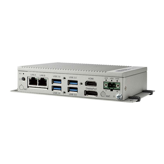
Introduction The UNO-2372G-J1 connectors are shown in Figures 2.1, 2.2, and 2.3. Additionally, a description of each peripheral is provided in the following sections. Figure 2.1 Front Panel of the UNO-2372G-J1 Single-Stack Model Figure 2.2 Rear Panel of the UNO-2372G-J1 Single-Stack Model Figure 2.3 Front Panel of the UNO-2372G-J1 Double-Stack Model Figure 2.4 Rear Panel of the UNO-2372G-J1 Double-Stack Model UNO-2372G-J1 User Manual... -
Page 17: Serial Communication Ports
Serial Communication Ports The UNO-2372G-J1 features four standard COM serial communication ports: COM1, COM2, COM3, and COM4. 2.2.1 COM Port Interfaces (COM1, COM2, COM3, COM4) The UNO-2372G-J1 is also equipped with four RS-232/422/485 ports (DB9, 50 ~ 115.2 kbps). The default setting for COM1 ~ 4 is RS-232. These settings can be adjusted in the BIOS menu. -
Page 18: Pci Express Mini Card Socket
PCI Express Mini Card Socket The UNO-2372G-J1 supports two full-size PCI Express mini card sockets. The loca- tion MINI1 interface with PCIe and USB signal is provided to support various exten- sion modules, such as Wi-Fi, 3G, and LTE modules, for diverse applications. The UNO-2372G-J1 double-stack model also supports the integration of iDoor modules (e.g., DI/O, COM, industrial fieldbus, etc.) via the MINI1 interface. -
Page 19: Chapter 3 Initial Setup
Chapter Initial Setup This chapter details UNO-2372G- J1 system configuration setup. I/O View Connecting Power Opening/Closing the Rear Cover Installing a Hard Disk Installing a Second Stack Exten- sion Kit... -
Page 20: I/O View
Connecting the Power This product is intended to be supplied by an approved power adapter or DC power source rated 10 - 36 V , 5.1-1.42A. (Please contact Advantech if you require addi- tional assistance) Opening/Closing the Rear Cover The rear cover can be opened in order to install a mPCIe module, mSATA SSD, and 2.5"... - Page 21 Slide the rear cover to the left to open the cover. Closing the rear cover: Align the guide pillars of the device with the brackets of the rear cover. Then slide the rear cover to the right to position in place. UNO-2372G-J1 User Manual...
-
Page 22: Installing A Hard Disk
Secure e rear cover in position using two screws. Then reattach the four rubber feet. Installing a Hard Disk Follow the steps outlined below to install a hard disk into the UNO-2372G-J1. Single-stack model: Disconnect the power cord. Unscrew and remove the rear cover. Screw the 2.5"... - Page 23 Connect a SATA cable to the HDD and motherboard. Then close the rear cover. Double-stack model: Disconnect the power cord. Remove the rubber feet of the rear cover. Unscrew and remove the rear cover. UNO-2372G-J1 User Manual...
- Page 24 Open Remove the screws to detach the second stack from the first stack. UNO-2372G-J1 User Manual...
- Page 25 Remove the screws to detach the HDD bracket from the second stack. Affix the HDD to the HDD bracket. Then affix the HDD bracket back onto the second stack using the screws provided. Connect a SATA cable to the HDD and motherboard. UNO-2372G-J1 User Manual...
- Page 26 Affix the second stack to the first stack using the screws provided. Replace the rear cover and affix in place using the two screws. Then replace the four rubber feet. UNO-2372G-J1 User Manual...
-
Page 27: Installing A Second Stack Extension Kit (Uno-2372G-Ekbe)
Installing a Second Stack Extension Kit (UNO- 2372G-EKBE) Remove the rear cover. Affix the second stack extension kit onto the first stack using four screws. Replace the rear cover and affix in place using two screws. Then replace the four rubber feet. UNO-2372G-J1 User Manual... - Page 28 UNO-2372G-J1 User Manual...
-
Page 29: Appendix A System Settings/Pin Assignments
Appendix System Settings/Pin Assignments... -
Page 30: Board Connectors, Sockets, And Switches
Board Connectors, Sockets, and Switches The UNO-2372G-J1 board features several connectors, sockets, and switches. The following sections explain how to configure the UNO-2372G-J1 hardware. Figure A.1 and A.2 show the locations of the connectors, sockets, and switches. Figure A.1 Connector, Socket, and Switch Locations (Top Side) UNO-2372G-J1 User Manual... - Page 31 Figure A.2 Socket and Switch Locations (Bottom Side) Table A.1: Connectors, Sockets, and Switches Category Label Function USB 3.0 Standard-A Dual Stacked Connector CN18 USB 3.0 Standard-A Dual Stacked Connector CN20 Phoenix 5.08mm 2P Power Terminal Block CN25 10/100/1000 Base-T RJ45 1x2 Tab Down Connector CN35 DisplayPort and HDMI Combo Receptacle Connector CN37...
-
Page 32: Usb 3.0 Connector (Cn5, Cn18)
USB 3.0 Connector (CN5, CN18) Table A.2: USB 3.0 Connector Pin Assignment Signal Type Rail/Tolerance Description VBUS Power 5V Suspend / 5V +5V Power Supply USB 2.0, negative differential pair I/O USB 3.3V Suspend / 3.3V signal USB 2.0, positive differential pair I/O USB 3.3V Suspend / 3.3V signal... -
Page 33: 10/100/1000 Base-T Rj45 Connector (Cn25)
10/100/1000 Base-T RJ45 Connector (CN25) Table A.4: 10/100/1000 Base-T RJ45 Connector Pin Assignment Name Type Description MDI0+ Analog Gigabit Ethernet Controller: Media Dependent Interface Differential Pairs 0,1,2,3. The MDI MDI0- Analog can operate in 1000, 100 and 10 Mbit / sec MDI1+ Analog modes. -
Page 34: Displayport Connector (Cn35)
DisplayPort Connector (CN35) Table A.5: DisplayPort Connector Pin Assignment Signal Type Rail Description ML_Lane 0 (p) O DP AC Coupled ‘True’ Signal – Main Link Lane 0 High Speed Main Link Lane 0 Ground ML_Lane 0 (n) O DP AC Coupled ‘Complement’... -
Page 35: Hdmi Connector (Cn35)
HDMI Connector (CN35) Table A.6: HDMI Connector Pin Assignment Signal Type Rail Description TMDS Data 2+ O TMDS AC Coupled TMDS channel 2 differential pair TMDS Data 2 Shield Shield for TMDS channel 2 TMDS Data 2– O TMDS AC Coupled TMDS channel 2 differential pair TMDS Data 1+ O TMDS AC Coupled TMDS channel 1 differential pair TMDS Data 1 Shield... -
Page 36: Audio Line Out Phone Jack (Cn37)
Audio Line Out Phone Jack (CN37) Table A.7: Audio Line Out Phone Jack Pin Assignment Name Type Rail Description Ground for Line Output Line Out (Left) Analog Line Output Left Channel Ground for Jack Detect Line Out (Right) Analog Line Output Right Channel Jack Detect 3.3V Jack Detect for Line Output... -
Page 37: Clear Cmos Jumper (Cn2)
Table A.9: RS-485 COM Port Connector Pin Assignment Name Type Rail Description RS-422 Transmit positive differential pair signal RS-422 Transmit negative differential pair signal RS-422 Receiver positive differential pair signal RS-422 Receive negative differential pair signal Signal ground Table A.10: RS-485 COM Port Connector Pin Assignment Name Type Rail... -
Page 38: Sata Power Wafer Box (Cn9)
A.11 SATA Power Wafer Box (CN9) Table A.12: RS-485 COM Port Connector Pin Assignment Name Type Rail Description SATA Power Power SATA Power Output Power Ground Power Ground N.C. Not Connected A.12 Micro SIM Card Connector (CN10) Table A.13: Micro SIM Card Connector Pin Assignment Name Type Rail... -
Page 39: Gpio 4Di/4Do Box Header (Cn11)
A.13 GPIO 4DI/4DO Box Header (CN11) Table A.14: GPIO 4DI/4DO Box Header Pin Assignment Name Type Rail Description Power DI/DO power output O OD 3.3V / 5V Digital Output 0 3.3V / 5V Digital Input 0 O OD 3.3V / 5V Digital Output 1 3.3V / 5V Digital Input 1... -
Page 40: Idoor Power Connector (Cn30)
A.15 iDoor Power Connector (CN30) Table A.16: iDoor Power Connector Pin Assignment Name Type Rail Description Power 10 ~ 36V iDoor PoE Power Output Power 10 ~ 36V iDoor PoE Power Output Power Ground Power Ground A.16 PCI Express Mini Card Socket (MINI1) Table A.17: PCI Express Mini Card Socket Pin Assignment Name Type... - Page 41 Table A.17: PCI Express Mini Card Socket Pin Assignment +3.3Vaux Power 3.3 V source PERST# I CMOS 3.3V Suspend Functional reset to the card W_DISABLE# I CMOS 3.3V A pull-up resistor to +3.3Vaux Return current path Mechanical key UIM_VPP O CMOS 3.3V Connect to Micro SIM CN10 C6 UIM_RESET O CMOS 3.3V...
-
Page 42: Pci Express Mini Card / Msata Socket (Mini2)
A.17 PCI Express Mini Card / mSATA Socket (MINI2) Table A.18: PCI Express Mini Card Socket Pin Assignment Name Type Rail Description Side even +3.3Vaux Power 3.3 V source Return current path +1.5V Power 1.5V source N.C. Not connected N.C. Not connected N.C. - Page 43 Table A.18: PCI Express Mini Card Socket Pin Assignment N.C. Not connected N.C. Not connected +3.3Vaux Power 3.3 V source +3.3Vaux Power 3.3 V source Return current path Return current path PETp0 I PCIe AC coupled PCI Express x1 data interface: one differential transmit pair.
- Page 44 Table A.19: mSATA Card Socket Pin Assignment N.C. Not connected N.C. Not connected Return current path Mechanical key N.C. Not connected N.C. Not connected N.C. Not connected N.C. Not connected N.C. Not connected +1.5V Power Return current path +3.3V Power 3.3 V source Side odd SATA_DET#...
-
Page 45: Sata Signal Host Plug Connector (Sata1)
A.18 SATA Signal Host Plug Connector (SATA1) Table A.20: SATA Signal Host Plug Connector Pin Assignment Name Type Rail Description Ground O SATA AC coupled Transmitter differential pair positive signal O SATA AC coupled Transmitter differential pair negative signal Ground I SATA AC coupled Receiver differential pair negative signal... -
Page 46: Ami Bios Setup
A.21 AMI BIOS Setup This section introduces how to set BIOS configuration data. A.21.1Introduction With the AMI BIOS Setup program, you can modify BIOS settings and control the specific fea- tures on your computer. The Setup program uses a number of menus for making changes and turning special features on or off. - Page 47 A.21.2.2Advanced BIOS Features Setup Select the Advanced tab from the UNO-2372G-J1 setup screen to enter the Advanced BIOS Setup screen. You can select any of the items in the left frame of the screen, such as “Trusted Computing” and hit <enter> to go to the sub menu for that item.
- Page 48 Trusted Computing All security related options can be set from this page. Security Device Support This item allows users to enable or disable “Security Device Support”. UNO-2372G-J1 User Manual...
- Page 49 ACPI Settings Enable ACPI Auto Configuration This item allows users to enable or disable “ACPI Auto Configuration”. Enable Hibernation This item allows users to enable or disable “Hibernation”. ACPI Sleep State This item allows users to set ACPI mode S3 (Suspend to RAM) or to Disable “ACPI Sleep State”.
- Page 50 IT8768E Super IO Configuration UNO-2372G-J1 supports 4 x RS-232/RS-422/RS-485. Each Serial Port can be enabled and disabled independently. The communication mode can be set to RS-232, RS-422 or RS-485 on demand. UNO-2372G-J1 User Manual...
- Page 51 EC Configuration This page shows EC firmware version and HW monitoring data. CPU Configuration Socket 0 CPU Information This item allows users to check complete CPU specifications. UNO-2372G-J1 User Manual...
- Page 52 CPU Power Management This item allows users to set CPU Power management including EIST, Turbo mode, and C-States. Network Stack Network Stack This item allows users to enable or disable for “Network Stack” (For using UEFI PXE function, please enable this item). UNO-2372G-J1 User Manual...
- Page 53 CSM Configuration CSM Support This item allows users to enable or disable for “CSM Support”. It is set to “dis- abled” by default for UNO-2372G-J1(Apollo-Lake platform). UNO-2372G-J1 User Manual...
- Page 54 USB Configuration Legacy USB Support This item allows users to enable or disable or set Auto for “Legacy USB Sup- port”. XHCI Hand-Off This item allows users to enable or disable “XHCI Hand-off”. USB Mass Storage Driver Support ...
- Page 55 A.21.2.3Chipset All chipset related items is shown at this page. North Bridge UNO-2372G-J1 User Manual...
- Page 56 This page shows memory information and provides options as below. Max TOLUD This item allows users to set maximum value of TOLUD (Top of Low Usable Dram). Above 4GB MMIO BIOS assignment This item allows users to enable or disable “above 4GB” setting. USB Configuration GOP driver ...
- Page 57 XHCI Mode This item allows users to enable or disable “XHCI Mode”. Wake on LAN This item has been set to support “Wake on LAN” function by default. UNO-2372G-J1 User Manual...
- Page 58 A.21.2.4Security Set Admin Password This item allows users to set “Administrator Password” if desired. The password will be required when entering BIOS setting page if it is set. User Password This item allows users to set “User Password” if desired. The password will be required when system boots if it is set.
- Page 59 Secure Boot This item allows users to enable or disable for "Secure Boot". A.21.2.5Boot Setup Prompt Timeout Number of Seconds to wait for showing period of Power On Self Test (POST). Extend the period to record BIOS version at POST screen if desired. Bootup NumLock State ...
- Page 60 A.21.2.6Save & Exit Save Changes and Exit This item allows users to save changes and exit. Discard Changes and Exit This item allows users to discard changes and exit. Save Changes and Reset This item allows users to save changes and reset. Discard Changes and Reset ...
- Page 61 UNO-2372G-J1 User Manual...
- Page 62 No part of this publication may be reproduced in any form or by any means, such as electronically, by photocopying, recording, or otherwise, without prior written permission from the publisher. All brand and product names are trademarks or registered trademarks of their respective companies. © Advantech Co., Ltd. 2020...
Need help?
Do you have a question about the UNO-2372G-J1 Series and is the answer not in the manual?
Questions and answers