
Related Manuals for Advantech UNO-3072L


Summary of Contents for Advantech UNO-3072L
-
Page 1: User Manual
UNO-3072L Celeron M/ Pentium M Embedded Automation Computer with Two PCI-Slot Extensions User Manual... - Page 2 Corp. All other product names or trademarks are properties of their respective owners. Support For more information on this and other Advantech products, please visit our websites at: http://www.advantech.com For technical support and service, please visit our support website at: http://www.advantech.com/support/...
- Page 3 Product Warranty (2 years) Advantech warrants to you, the original purchaser, that each of its prod- ucts will be free from defects in materials and workmanship for two years from the date of purchase. This warranty does not apply to any products which have been repaired or...
-
Page 4: Declaration Of Conformity
This product has passed the CE test for environmental specifications when shielded cables are used for external wiring. We recommend the use of shielded cables. This kind of cable is available from Advantech. Please contact your local supplier for ordering information. - Page 5 Safety Instructions Read these safety instructions carefully. Keep this user manual for later reference. Disconnect this equipment from DC outlet before cleaning. Do not use liquid or spray detergents for cleaning. For pluggable equipment, the power outlet shall be installed near the equipment and shall be easily accessible.
- Page 6 CPU card or other cards while the PC is on. Disconnect power before making any configuration changes. The sudden rush of power as you connect a jumper or install a card may damage sensitive electronic components. UNO-3072L User Manual...
-
Page 7: Table Of Contents
Contents Chapter 1 Overview ............2 Introduction ............... 2 Hardware Specifications ........... 5 Safety Precautions ............. 7 Chassis Dimensions............8 Packing List..............10 Chapter 2 Hardware Functionality ....... 12 Introduction ..............12 RS-232 Interface (COM1~COM2) ......... 13 RS-232/422/485 Interface (COM3~COM4) ....13 2.3.1 16C550 UARTs with 16-byte FIFO Standard ..... - Page 8 Inserting a CompactFlash Card ........36 Connecting Power ............36 Installing a Hard Disk ............. 37 Installing a PCI-bus Card ..........37 Mounting UNO-3072L............ 39 Installing Power Cable ............ 40 UNO-3072LMounting Caution ........41 BIOS Setup and System Assignments ......42 Appendix A System Settings and Pin Assignments ..
- Page 9 Overview This chapter provides an overview of UNO-3072Lspecifications. Sections include: • Introduction • Hardware specification • Safety precautions • Chassis dimensions...
-
Page 10: Chapter 1 Overview
3072L combines the best features of a PC, including the processor, RAM, and powerful software, with the reliability, ruggedness, and distributed nature of a PLC. UNO-3072L has the compact size and ruggedness of a PLC, and the software flexibility and functionality of a PC. It's an ideal platform for sophisticated control and logging in rugged environments. - Page 11 Off-the-shelf Universal PCI Extensions From a computing point of view, the UNO-3072L with its PC-based con- trol CPU is a high-end machine controller. It can be simply operated with the onboard Ethernet interface or with a PC Fieldbus card. Two free PCI slots are also available.
- Page 12 UNO-3072L features onboard DI and DO. These DIs and DOs can be used as 32-bit counters or to handle alarms and events. Any events can be passed to UNO-3072L through DIs with an additional DI plug-in card. UNO-3072L can also output alarms through onboard DOs immediately to notify key personnel about urgent events.
-
Page 13: Hardware Specifications
1.2 Hardware Specifications • CPU: Celeron M 1GHz CPU (non-cache) Celeron M 1.5GHz CPU ( 1MB cache) • Memory: 1x 200 pin SODIMM socket, supports up to 1GB DDR RAM • BIOS: Award 4MB flash memory, supports Boot-on-LAN function • Interface I/O: VGA/Keyboard/Mouse DB-15 VGA Connector, PS/2 keyboard and mouse •... - Page 14 • Chassis Size (WxHxD): 140 x 177 x 237 mm (5.5”x 7.0”x9.3”) for C-M 1G 153.4 x 177 x 237 mm (6”x 7.0”x 9.3”) for C-M 1.5G or faster CPU • Mounting: Wall/Panel/Stand mount • Weight: 4.2 kg • Software OS: Microsoft Windows XP Embedded, Windows CE 5.0, Windows 2000/XP, Linux UNO-3072L User Manual...
-
Page 15: Safety Precautions
Note: Always ground yourself to remove any static electric charge before touching UNO-3072L. Modern elec- tronic devices are very sensitive to static electric charges. Use a grounding wrist strap at all times. Place all electronic components on a static-dissipative surface or in a static-shielded bag. -
Page 16: Chassis Dimensions
1.4 Chassis Dimensions Figure 1.1: Chassis Dimensions for C-M 1GHz CPU UNO-3072L User Manual... - Page 17 Figure 1.2: Chassis Dimensions for C-M 1.5GHz or faster CPU Chapter 1...
-
Page 18: Packing List
(D) Driver and Utility CD-ROM (E) 2 x nti-vibration rubber (F) PCI expansion to hold 2nd anti-vibration rubber (G) Mini Jumper (H) Paper menu ( I ) Power connector (J) IDE cable for 2.5" HDD Figure 1.3: UNO-3072L Accessories UNO-3072L User Manual... - Page 19 Hardware Functionality This chapter shows how to setup the UNO-3072Lhardware functions, including connecting peripherals, and setting switches and indicators. Sections include: • Introduction • RS-232 Interface • RS-232/422/485 Interface • LAN / Ethernet Connector • DI/O and Counter • Power Connector •...
-
Page 20: Chapter 2 Hardware Functionality
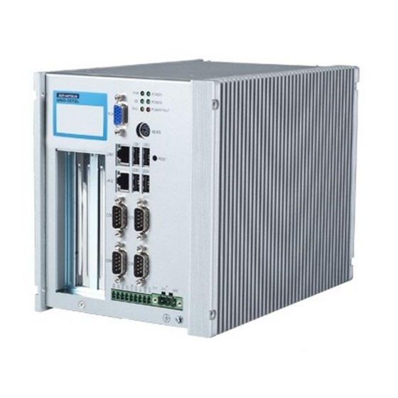
Chapter 2 Hardware Functionality 2.1 Introduction The figures below show the connectors on UNO-3072L, and following sections give you detailed information about function of each peripheral. Figure 2.1: Front Panel of UNO-3072L UNO-3072L User Manual... -
Page 21: Rs-232 Interface (Com1~Com2)
422/485. (Please refer to section 2.3.4 for how to determine RS-232 or RS-422/485) 2.3.1 16C550 UARTs with 16-byte FIFO Standard Advantech UNO-3072Lcomes with 16C550 UARTs containing 16 bytes FIFOs. 2.3.2 RS-422/485 Detection In RS-422/485 mode, UNO-3072Lautomatically detects signals to match RS-422 or RS-485 networks. -
Page 22: Rs-232/422/485 Selection
Then no handshaking is necessary. In RS-422, if DIP switch is set to “On”, the driver is always enabled, and always in high or low status. UNO-3072L User Manual... -
Page 23: Irq, I/O Address And Transmission Rate Setting
Table 2.1: Auto Flow Control and RS-422 Slave/Master Selection SW2 DIP Switch Setting COM Port Mode Selections COM3 RS-422: Slave mode RS-485: Auto flow control COM4 RS-422: Slave mode RS-485: Auto flow control COM3 RS-422: Master mode RS-485: N/A COM4 RS-422: Slave mode RS-485: Auto flow control COM3... - Page 24 * To increase the normal baud rates by eight times, (e.g. if we set the baud rate as 115.2K bps in software, then the actual hardware baud rate will be increased to 921.6K bps), set switch 2 of SW3 to “on”. Note: Only COM3 and COM4 can adjust the transmission rate. UNO-3072L User Manual...
-
Page 25: Termination Resistor (Jp6)
2.3.7 Termination Resistor (JP6) The onboard termination resistor (120 ohm) for COM3/COM4 can be used for long distance transmission or device matching (Default Open). RS-422 RS-485 COM3 Close A TX3-TR Data+, Data- Close B RX3-TR COM4 Close C TX4-TR Data+, Data- Close D TX4-TR Close: Enable termination resistor. -
Page 26: Isolated Inputs
Counter 0 and Counter 1; While DI1 and DI3 may be configured as input pins of Counter 0 and Counter 1. Please refer to section 2.7 for details. Note: Please refer to Appendix A.3 Table A.6 for command of DI UNO-3072L User Manual... -
Page 27: Interrupt Function Of The Di Signals
The channels are connected to the interrupt circuitry. Users can disable/ enable interrupt function, select trigger type or latch the port data by set- ting the Interrupt Control Register of the UNO-3072L(refer to section 2.5.5 below). When the interrupt request signals occur, then the software will service these interrupt requests by ISR (Interrupt Service Routine). -
Page 28: Interrupt Control Register
Interrupt Disable/Enable Control Disable Enable The user can choose to enable or disable the interrupt function by writing its corresponding value to the interrupt disable/enable control bit in the interrupt control register, as shown in Table 2.6. UNO-3072L User Manual... -
Page 29: Interrupt Triggering Edge Control
Write Don’t care Clear interrupt Note: UNO-3072Lprovides built-in examples to show how to deliver digital input functionality. Refer to console mode examples in C:\Pro- gram Files\Advantech\UNO\UNO_IsaDIO\Examples\Console. (Please install DI/O driver from the UNO CD to use these examples) Chapter 2... -
Page 30: Onboard Isolated Digital Output
When the system is hot reset, then the status of iso- lated digital output channels are selected by jumper JP7. Table 2.10 shows the configuration of jumper JP7. Note: Please refer to Figure A.4 and A.5 for location of JP7 UNO-3072L User Manual... -
Page 31: Isolated Outputs
UNO-3072L. Please take care that the current through each DO pin not exceed 200 mA. Figure 2.8 below shows how to connect an external output load to the UNO-... -
Page 32: Onboard Isolated Counter/Timer
Table 2.11 shows the bit map of the Counter/Timer Control Register. The register is readable/writable register. While being written, it is used as a control register; and while being read, it is used as a status register. UNO-3072L User Manual... - Page 33 Table 2.11: Counter/Timer Control Register Bit Map Base Address 207H R/W Interrupt Flag/Clear Register CTR1F CTR0F 208H R/W 82C54 Chip Counter0 Register 209H R/W 82C54 Chip Counter1 Register 20BH R/W 82C54 Chip Control Register 20CH R/W Counter0 Start Control / Output Status Register CTR0 CTR0 Gate...
-
Page 34: Counter 0 Function Block
2.7.2 Counter 0 Function Block Figure 2.8: Counter 0 Function Block 2.7.3 Counter 1 Function Block Figure 2.9: Counter 1 Function Block UNO-3072L User Manual... -
Page 35: 32-Bit Counter Function Block (Ctr32Set=1)
2.7.4 32-bit Counter Function Block (CTR32Set=1) Figure 2.10: 32-bit Counter Function Block 2.7.5 Counter Clock Source There are two clock sources available for the user counters by setting counter clock control bits - CTR0CLKSet and CTR1CLKSet. Table 2.12: Counter Clock Source Control Bit CTR0CLKSet Internal clock (default) External clock from digital input 1 (DI1) chan-... -
Page 36: Counter Gate Source
“1” to this bit. This bit must first be cleared to service the next coming interrupt. Besides, you can choose if counter 0 or counter 1 generate interrupt signal by configuring “CTR0IntSet” and “CTR1IntSet” control bit. UNO-3072L User Manual... -
Page 37: Cascaded 32-Bit Counter
Cascade counter 0 and counter 1 into one 32-bit counter Note: UNO-3072Lprovides built-in examples to show how to deliver counter functionality. Refer to console mode examples in C:\Program Files\Advantech\UNO\UNO_IsaDIO\Examples\Console. (Please install DI/O driver from the UNO CD to use these examples) 2.8 Power Input UNO-3072Lcomes with a Phoenix connector that carries 16~36 VDC external power input, and features reversed wiring protection. - Page 38 Note: UNO-3072Lprovides built-in examples to show how to monitor power input status. Refer to console mode examples in C:\Program Files\Advantech\UNO\UNO_IsaDIO\Examples\Console. (Please install DI/O driver from the UNO CD to use these examples) UNO-3072L User Manual...
-
Page 39: Led And Buzzer For System Diagnosis
Figure 2.12: LED Indicators Location to Monitor Power Input Situation Table 2.18: Power Register Bit Map 218H Power Register PWR P2 =0, Power fail =1, Power normal P1 (24V) =0, Power input 1 fail =1, Power input 1 normal P2 (24V*) =0, Power input 2 fail =1, Power input 2 normal 2.9 LED and Buzzer for System Diagnosis... - Page 40 SPKS0 & SPKS1: Buzzer alarming setting bit (refer to Table 2.21) Note: UNO-3072Lprovides built-in examples to show how to configure DIAG LED and Buzzer. Refer to console mode examples in C:\Program Files\Advantech\UNO\UNO_IsaDIO\Examples\Console. (Please install DI/O driver from the UNO CD to use these examples) UNO-3072L User Manual...
-
Page 41: Ps/2 Keyboard And Mouse Connector
2.10 PS/2 Keyboard and Mouse Connector The UNO-3072Lprovides a PS/2 keyboard and PS/2 mouse connector. A 6-pin mini-DIN connector is located on the front panel. UNO-3072L comes with an adapter in the accessory package (see section 1.5) to con- vert from the 6-pin mini-DIN connector to two 6-pin mini-DIN connectors for PS/2 keyboard and PS/2 mouse connection. -
Page 42: Vga Display Connector
2.12 VGA Display Connector The UNO-3072L provides a VGA controller (Intel 855GME GMCH ICH4 Chipset 400MHz FSB) for a high resolution VGA interface. It supports up to 1280 x 1024 @ 16bpp (60Hz). 2.13 Reset Button Press the "Reset" button to activate the reset function. - Page 43 Initial Setup This chapter introduces how to initialize the UNO-3072L. Sections include: • Introduction • Inserting a CompactFlash Card • Chassis Grounding • Connecting Power • Connecting a Hard Disk • BIOS Setup and System Assignments...
-
Page 44: Chapter 3 Initial Setup
Screw back the top cover with four screws. 3.2 Connecting Power Connect the UNO-3072L to a 16 ~ 36 VDC power source. The power source can either be from a power adapter or an in-house power source. UNO-3072L User Manual... -
Page 45: Installing A Hard Disk
3.3 Installing a Hard Disk The procedure for installing a hard disk into the UNO-3072L is listed below. Please follow these steps carefully. Remove the power cord. Unscrew the two screws from the upper HDD cover Unscrew the four screws from the upper cover and remove it. - Page 46 2nd anti-vibration rubber towards the 2nd PCI card until it is fixed. Figure 3.3: 2nd PCI-bus Card Installation Cut off a part of the anti-vibration rubber if it is too long to fit into the box when the PCI card is fixed. UNO-3072L User Manual...
-
Page 47: Mounting Uno-3072L
Figure 3.4: Adjust the Size of the Anti-Vibration Rubber Screw back the upper cover with the four screws. 3.5 Mounting UNO-3072L There are 3 types of mounting kits for UNO-3000 series: • Panel mount • Stand mount • Wallmount Pls refer to UNO-3000 Series Accessories Manual Note: Due to thermal performance issues, Wallmount will only support specific models. -
Page 48: Installing Power Cable
UNO-3072Lprovides an internal backup power source so that it can pro- vide power for a CD-ROM, DVD-ROM or other external devices. You can use the power cable from accessory package (see section 1.5). Y ellow +12V Black Black Figure 3.5: Internal Backup Power Source UNO-3072L User Manual... -
Page 49: Uno-3072Lmounting Caution
3.7 UNO-3072LMounting Caution Figure 3.6: UNO-3072L Improper Installation (1) Figure 3.7: UNO-3072L Improper Installation (2) Chapter 3... -
Page 50: Bios Setup And System Assignments
SOM-4486. Y ou can find this manual on the driver and utility CD of UNO- 3072L in the accessory package. Please note that you can try to “LOAD DEFAULTS” from the BIOS Setup manual if the UNO-3072L does not work properly. - Page 51 System Settings and Pin Assignments...
-
Page 52: Appendix A System Settings And Pin Assignments
360-36F LPT2 378-37F Parallel printer port 1 (LPT1) 380-38F SDLC, bisynchronous 2 3A0-3AF Bisynchronous 1 3B0-3BF Monochrome display 3C0-3CF Reserved 3D0-3DF Color/graphics monitor adapter 3F0-3F7 Diskette controller 3E8-3EF Serial port 3 3F8-3FF Serial port 1 Watchdog timer UNO-3072L User Manual... - Page 53 Table A.2: UNO-3072LInterrupt Assignments Interrupt No. Interrupt Source IRQ 0 Interval timer IRQ 1 Keyboard IRQ 2 Interrupt from controller 2 (cascade) IRQ 3 COM2 IRQ 4 COM1 IRQ 5 COM4 (Independent IRQ) IRQ 6 Diskette controller (FDC) IRQ 7 DI/O IRQ 8 Real-time clock...
-
Page 54: Board Connectors And Jumpers
UNO-3072Lhardware set- ting. Figures A.1 to A.7 show the location of UNO-3072Lconnectors and jumpers. Figure A.1: Backplane Connector and Jumper Locations Figure A.2: Mainboard Connector and Jumper Locations (Backside) UNO-3072L User Manual... - Page 55 Table A.3: Connector and Jumper Descriptions Location Label Function Backplane Phoenix power connector Internal power source (Reserved) DIO connector Communication slot for UNO-3072L main board PICMG1 Communication slot for UNO-3072L main board PCI1 PCI slot 1 PCI2 PCI slot 2...
- Page 56 Ethernet1/USB1/USB2 ports CON2 Ethernet2/USB3/USB4 ports Lithium battery for BIOS COM3/COM4 RS-422 master/slave selec- tion Share IRQ/Independent IRQ selection and Speed selection CompactFlash 1 master/slave selection COM3 RS-232/422/485 selection COM4 RS-232/422/485 selection COM3/COM4 terminator resistor Digital output latch/non-latch UNO-3072L User Manual...
-
Page 57: Uno-3072Lcontrol Register
A.3 UNO-3072LControl Register Table A.5: UNO-3072LControl Register Base Address 200H Isolated Digital Input Status Register 201H Isolated Digital Output Control/Status Register 202H Interrupt Enable Control/Status Register DI1EN DI0EN 203H Interrupt Triggering Edge Control/Status Register DI1TE DI0TE 207H Interrupt Flag/Clear Register CTR1F CTR0F DI1F DI0F 208H... -
Page 58: Rs-232 Standard Serial Port (Com1~Com2)
A.4 RS-232 Standard Serial Port (COM1~COM2) Table A.6: RS-232 Standard Serial Port Pin Assignments RS-232 Signal Name UNO-3072L User Manual... -
Page 59: Rs-232/422/485 Serial Port (Com3~Com4)
A.5 RS-232/422/485 Serial Port (COM3~COM4) Table A.7: RS-232/422/485 Serial Port Pin Assignments RS-232 RS-422 RS-485 DATA- DATA+ A.6 Ethernet RJ-45 Connector (LAN1~LAN2) Table A.8: Ethernet RJ-45 Connector Pin Assignments 10/100Base-T Signal Name XMT+ XMT- RCV+ RCV- Appendix A... -
Page 60: Power Screw Terminal (Pwr)
A.7 Power Screw Terminal (PWR) Figure A.8: Power Connector Pin Assignments Table A.9: Power Connector Pin Assignments Signal Name Power input 1; Range: 16~36 VDC (P1) +Vs* Power input 2; Range: 16~36 VDC (P2) Ground UNO-3072L User Manual... -
Page 61: Ps/2 Keyboard And Mouse Connector
A.8 PS/2 Keyboard and Mouse Connector Table A.10: Keyboard and Mouse Connector Pin Assignments Signal Name KB DATA MS DATA KB Clock MS Clock A.9 USB Connector (USB1~USB4) Table A.11: USB Connector Pin Assignments Signal Name Cable Color DATA+ White DATA- Green Black... -
Page 62: Vga Display Connector
A.10 VGA Display Connector Table A.12: VGA Adaptor Cable Pin Assignmen Signal Name Green Blue H-SYNC V-SYNC UNO-3072L User Manual... - Page 63 Programming the Watchdog Timer...
-
Page 64: Appendix B Programming The Watchdog Timer
OUT DX,AL MOV DX,2FH MOV AL,00H OUT DX,AL; MOV DX,2EH MOV AL,F6H OUT DX,AL MOV DX,2FH MOV AL,05H; Set 5 seconds OUT DX,AL ;------------------------------------------ ; Exit extended function mode | ;------------------------------------------ MOV DX,2EH MOV AL,AAH OUT DX,AL UNO-3072L User Manual...
Need help?
Do you have a question about the UNO-3072L and is the answer not in the manual?
Questions and answers