
Related Manuals for Advantech UNO-4683


Summary of Contents for Advantech UNO-4683
-
Page 1: User Manual
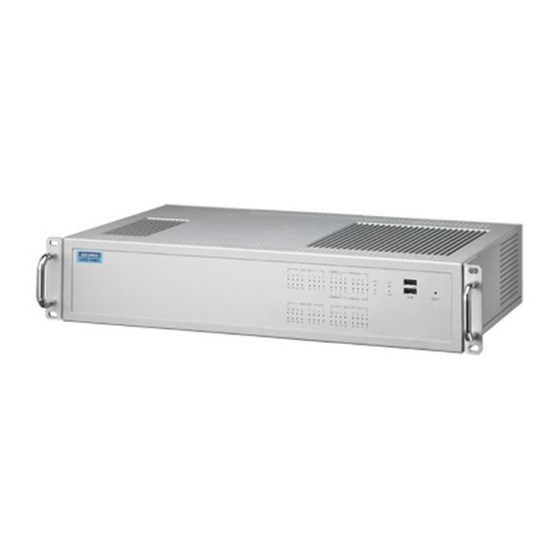
UNO-4683 Intel Core i7 Dual Core Automa- tion Computer with 6xLAN, 2xCOM, 3 expansion slots User Manual... - Page 2 Corp. All other product names or trademarks are properties of their respective owners. Support For more information on this and other Advantech products, please visit our websites at: http://www.advantech.com For technical support and service, please visit our support website at: http://www.advantech.com/support/...
- Page 3 Product Warranty (2 years) Advantech warrants to you, the original purchaser, that each of its prod- ucts will be free from defects in materials and workmanship for two years from the date of purchase. This warranty does not apply to any products that have been repaired or...
- Page 4 Step 1. Visit the Advantech web site at www.advantech.com/support where you can find the latest information about the product. Step 2. Contact your distributor, sales representative, or Advantech's cus- tomer service center for technical support if you need additional assistance. Please have the following information ready before...
- Page 5 Safety Instructions Read these safety instructions carefully. Keep this User's Manual for later reference. Disconnect this equipment from any AC outlet before cleaning. Use a damp cloth. Do not use liquid or spray detergents for clean- ing. For plug-in equipment, the power outlet socket must be located near the equipment and must be easily accessible.
- Page 6 The sound pressure level at the operator's position according to IEC 704- 1:1982 is no more than 70 dB (A). DISCLAIMER: This set of instructions is given according to IEC 704-1. Advantech disclaims all responsibility for the accuracy of any statements contained herein. Safety Precaution - Static Electricity Follow these simple precautions to protect yourself from harm and the products from damage.
-
Page 7: Table Of Contents
Figure 1.1:Chassis Dimensions ........8 Packing List............... 8 Chapter 2 Hardware Functionality ....... 10 Overview ................. 10 Figure 2.1:UNO-4683 Front Panel ......10 Figure 2.2:UNO-4683 Rear Panel ....... 10 LED Indicators ..............11 2.2.1 System Status Indicators ..........11 Table 2.1:Definition of System Status Indicators ..11 2.2.2... - Page 8 BIOS Setup and System Assignments ......31 Appendix A System Settings & Pin Assignments .... 34 System I/O Address & Interrupt Assignments....34 Table A.1: UNO-4683 System I/O Ports ..... 34 Table A.2:UNO-4683 Interrupt Assignment ....35 RS-232/422/485 Serial Ports (COM1~COM2)....36 Table A.3:RS-232 Serial Ports COM1~2 ....
- Page 9 Overview This chapter provides an overview of UNO-4683’s specifications. Sections include: • Introduction • Hardware Specifications • Safety Precautions • Chassis Dimensions • Packing List...
-
Page 10: Chapter 1 Overview
With these expansion slots, UNO-4683 can optional equips isolated serial ports, IRIG-B, as well as fiber optical Ethernet interface. If user need to plug in the ordinary plug-in card, UNO-4683 can also sup- port the interface module to provide PCI, PCIe-mini card slot, mini-PCI and PCI-104. - Page 11 LEDs on the front panel for all ports and modes highly simplify monitoring for operation and maintenance in the rack. You could easily mount UNO-4683 on rack, manage all UNOs in one rack and eas- ily develop your application on rack.
- Page 12 HDD. There is no need to waste time and energy on developing onboard device drivers or using the Platform Builder to build a custom Windows CE image, they have all been done for the Advantech UNO-4683 series! Through the built-in runtime library and Software Development Kit (SDK), the UNO-4683 series leverages your existing Windows-based programming skills to rapidly develop applications.
-
Page 13: Hardware Specifications
OS Support WES, Windows XP Embedded, Windows 2000/XP, Windows CE 6.0, Linux, QNX System Design Fanless with no internal cabling Remote Management Built-in Advantech DiagAnywhere agent on Windows CE/XPe System Hardware Intel Dual Core i7 620LE 2.0GHz Memory 4G DDR3 SDRAM... - Page 14 IEC 60068-2-27 CompactFlash 50 G half sine, 11 ms HDD: 20 G half sine, 11 ms Vibration Protection EC 60068-2-64 (Random 1 Oct./min, 1hr/ axis.) CompactFlash? 2 Grms @ 5 ~ 500 Hz, HDD: 1 Grms @ 5 ~ 500 Hz UNO-4683 User Manual...
-
Page 15: Safety Precautions
Caution! Always ground yourself to remove any static electric charge before touching UNO-4683. Mod- ern electronic devices are very sensitive to static electric charges. Use a grounding wrist strap at all times. Place all electronic components on a static-dissipative surface or in a static-shielded bag. -
Page 16: Chassis Dimensions
1.4 Chassis Dimensions Figure 1.1: Chassis Dimensions 1.5 Packing List The accessory package of UNO-4683 contains the following items: (A) UNO-4683 (B) 2 x rack mounting kit (C) 12 x screw for rack mount kit (D) 2 x front handles... - Page 17 Hardware Functionality This chapter shows how to setup the UNO-4683’s hardware functions, including connecting peripherals, set- ting switches and indicators. Sections include: • Overview • LED Indicators • Power Input • RS-232 Interface • RS-232/422/485 Interface • LAN / Ethernet Connector •...
-
Page 18: Figure 2.1:Uno-4683 Front Panel
Chapter 2 Hardware Functionality 2.1 Overview The following two figures show the indicators, connectors and expansion slots on the UNO-4683. The following sections give you detailed infor- mation about function of each peripheral. Figure 2.1: UNO-4683 Front Panel Figure 2.2: UNO-4683 Rear Panel... -
Page 19: Led Indicators
2.2 LED Indicators The LEDs in the front panel can be divided into 4 groups. 2.2.1 System Status Indicators Table 2.1: Definition of System Status Indicators Item LED Status Description Green System power is on System power is off Green Data being received/ transmitted between on CF/SATA No Data being received/ transmitted on CF/... -
Page 20: Lan Status Indicators
2.2.2 LAN Status Indicators Table 2.2: Definition of LAN Status Indicators Item Status Description Green 1Gbps network link LAN/Link Orange 100Mbps network link (Port 1~2) 10Mbps network link or invalid network link Orange 100Mbps network link LAN/Link (Port 3~6) 10Mbps network link or invalid network link Green Ethernet date being received/ transmitted LAN/Active... -
Page 21: Serial Communication Status Indicators
2.2.3 Serial Communication Status Indicators Table 2.3: Definition of Serial COM Status Indicators Item LED Status Description Green Serial port data being received COM/Rx (Port 1,2) No data being received Orange Serial port data being transmitted COM/Tx (Port 1,2) No data being transmitted 2.2.4 Indicators for Expansion Slots These LED indicators are defined by the UNOP series expansion modules, please refer to the related document for the definition. -
Page 22: Power Input
2.3 Power Input The UNO-4683 support AC/DC power input to fulfill the need of field site. Following table shows the specification of the power input. Table 2.4: AC/DC Power Input AC/DC Volt. Range Power Rating Connector Type 90-250V 2 - 0.8A, 47- 63Hz... -
Page 23: Specification Of The Relay
2.3.1 Specification of the Relay Relay output type: Form C Contact: 5A@250V 5A@30V Breakdown Voltage: 500V (50/60Hz) Contact Resistance: 30mΩ (maximum) Insulation Resistance: 1GΩ (maximum) at 500V 2.3.2 Wiring Diagram of the Relay Figure 2.3: Event Relay Connection Chapter 2... -
Page 24: Rs-232/422/485 Interface (Com1, Com2)
Advantech UNO-4683 comes with Oxford OXuPCI952 UARTs contain- ing 128 bytes FIFOs. 2.4.2 RS-422/485 Detection In RS-422/485 mode, UNO-4683 automatically detects signals to match RS-422 or RS-485 networks. (No jumper change required) 2.4.3 Automatic Data Flow Control Function for RS-485 In RS-485 mode, UNO-4683 automatically detects the direction of incoming data and switches its transmission direction accordingly. -
Page 25: Terminal Resistor (Sw6,Sw8)
2.4.4 Terminal Resistor (SW6,SW8) The onboard termination resistor (120 ohm) for COM1, COM2 can be used for long distance transmission or device matching. (Default Open.) Please also refer to Table 2.9 for the mapping table of Jumper and COM port. Table 2.6: Jumper setting of terminal resistor Status Description... -
Page 26: Rs-232/422/485 Selection
2.4.5 RS-232/422/485 Selection COM1, COM2 support RS-232, RS-422 and RS-485 interfaces. The sys- tem detects RS-422 or RS-485 signals automatically in RS-422/485 mode. To select between RS-422/485 and RS-232 for COM1, COM2, adjust CN12, CN14 and Table 2.9 shows the mapping table. Jumper settings for RS-422/485 interface: (CN12, CN14) Figure 2.4: RS-422/485 Jumper Setting Jumper settings for RS-232 interface: (Default setting) (CN12, CN14) -
Page 27: Rs-485 Auto Flow & Rs-422 Master/Slave Modes
RS-485: Auto flow control 2.4.7 Redundant RS-422 Matter In the occasion that UNO-4683 RS-422 ports need to act as multi-master in parallel with other RS-422 master ports. Because of the auto detection function, the TX port will also receive data from other RS-422 master. To avoid this situation in this kind of application, user can use SW5and SW7 to turn it off, then no data will be received from TX port. -
Page 28: Lan: Ethernet Connector
The USB interface complies with USB UHCI, Rev. 2.0 compliant. The USB interface can be disabled in the system BIOS setup. UNO-4683 provides 2 USB port on the front panel, and 3 USB port on the rear panel. It also provides 1 USB port inside the chassis for USB dongle key. -
Page 29: Battery Backup Sram
There is a BTR LED in the front panel of the UNO-4683, please replace the lithium battery with a new one if the BTR LED is activated. -
Page 30: Relay Output For Event
2.9 Relay Output for Event To reduce the down time of device or prevent the system fail, UNO-4683 provides the relay output function for some events. There is a OR gate to handle these events with the relay output. The SW9 can enable or disable the linkage of each event with the relay output. -
Page 31: Expansion Slots
All the expanding IO modules are design for embedded application, the power efficiency and thermal are well controlled. But if 3rd plug-in card is required to work in the UNO-4683, please check the related power con- sumption and working condition carefully. In the normal condition, the... - Page 32 UNO-4683User Manual...
- Page 33 Initial Setup...
-
Page 34: Chapter 3 Initial Setup
Remove the plug-in module in the slot 3 Remove the screws on the cover Install a Well-configured CompactFlash Card in this area Install a USB device in this area Refer to this manual to configure the COM ports UNO-4683 User Manual... -
Page 35: Figure 3.1:Location For Configuration
Figure 3.1: Location for Configuration 3.2 Install a USB Dongle UNO-4683 provides a clamp to fix the USB dongle which can be installed inside the chassis. Please follow the steps to install the USB don- gle and clamp: 1. Please follow 3.1 to open the cover for configuration. -
Page 36: Install A Hard Disk
3.3 Install a Hard Disk Please follow the steps below to install an HDD: Turn the heat-sink side down. Unscrew the screws and get the HDD bay apart. Insert the HDD into the HDD bay and screw it. UNO-4683 User Manual... -
Page 37: Figure 3.2:Location Of Sata Connections
Connect the SATA cable between HDD and connector then assem- ble the HDD back to the chassis. The locations of the connectors are below HDD Bay. SATA 0 SATA 1 Figure 3.2: Location of SATA connections Chapter 3... -
Page 38: Installing In A Rack
Please screw the ears and handles at the position indicated below. The same on the other side. Use the 4 screw holes to mount the UNO-4683 on the rack. UNO-4683 equips the Aluminum Fins on the top of the unit as heat-sink. -
Page 39: Bios Setup And System Assignments
UNO-4683 adopts Advantech's SOM-5788 CPU module. Further information about the SOM module, can be found in SOM's user's manual. You can find this manual on the UNO-4683's companion DISC. Please note that you can try to "LOAD BIOS DEFAULTS" from the BIOS Setup manual if the UNO-4683 does not work properly. - Page 40 UNO-4683 User Manual...
- Page 41 System Settings and Pin Assignments...
-
Page 42: Appendix A System Settings & Pin Assignments
Appendix A System Settings & Pin Assignments A.1 System I/O Address & Interrupt Assignments Table A.1: UNO-4683 System I/O Ports Address Range Device 000-01F DMA controller (slave) 020-03F Interrupt controller 1, (master) 040-05F 8254 timer/counter 060-06F 8042 (keyboard controller) 070-07F... -
Page 43: Table A.2:Uno-4683 Interrupt Assignment
Table A.2: UNO-4683 Interrupt Assignment Interrupt No. Interrupt Source Parity error detected IRQ 0 Interval timer IRQ 1 Keyboard IRQ 2 Interrupt from controller 2 (cascade) IRQ 8 Real-time clock IRQ 11 Reserved for watchdog timer IRQ 12 PS/2 mouse... -
Page 44: Rs-232/422/485 Serial Ports (Com1~Com2)
A.2 RS-232/422/485 Serial Ports (COM1~COM2) Table A.3: RS-232 Serial Ports COM1~2 RS-232 RS-422 RS-485 DATA- DATA+ UNO-4683 User Manual... -
Page 45: Usb Connectors
A.3 USB Connectors Table A.4: USB Connector Pin Assignments Signal name Cable Color DATA- White DATA+ Green Black A.4 DVI-I Connector Table A.5: DVI Connector Pin Assignments Signal Name TMDS_C2# TMDS_C2 CRT_DDC_CLK CRT_DDC_DATA MDVI_CLK MDVI_DATA VGAVSY TMDS_C1# TMDS_C1 VCC_DVI VGA Detect HP_DET Appendix A... - Page 46 Table A.5: DVI Connector Pin Assignments TMDS_C0# TMDS_C0 TMDS_CK# TMDS_CK VGAR VGAG VGAB VGAHSY UNO-4683 User Manual...
-
Page 47: Sata Hard Drive Raid Support
A.5 SATA Hard Drive RAID Support In order to install an operating system onto a RAID volume, the RAID option must be enabled in the system BIOS, a RAID volume must be cre- ated, and the F6 installation method must be used to load the Intel Rapid Storage Technology driver during operating system setup. - Page 48 POST, press Ctrl and i at the same time to enter the option ROM user interface. Select 1: Create RAID Volume and press Enter. Use the up or down arrow keys to select the RAID level and press Enter. UNO-4683 User Manual...
- Page 49 Unless you have selected RAID 1, use the up or down arrow keys to select the strip size and press Enter. Press Enter to select the physical disks. Select the appropriate number of hard drives by using the up or down arrow keys to scroll through the list of hard drives and press Space to select the drive.
- Page 50 Note: Nothing will happen immediately after pressing F6. Setup will temporarily continue loading drivers. You will then be prompted with a screen asking you to load support for mass storage device(s). Press S to Specify Additional Device. UNO-4683 User Manual...
- Page 51 When you see a prompt that says, Please insert the disk labeled Manufacturer-supplied hardware support disk into Drive A:, insert ;a floppy disk containing the following files: IAAHCI.INF, IAAHCI.CAT, IASTOR.INF, IASTOR.CAT, IASTOR.SYS, and TXTSETUP.OEM. Note: Use the Floppy Configuration Utility to create a floppy disk with the necessary files or copy required file from driver folder.
- Page 52 UNO-4683 User Manual...
- Page 53 Watchdog Timer Register Appendix B...
-
Page 54: Appendix B Watchdog Timer Register
Appendix B Watchdog Timer Register Register 1: WatchDogTimer Load (WDTLOAD) OFFSET = 0x000 WDTLOAD serves as a countdown timer. Once an 8-bit width value is loaded into the register, it starts to count down to zero automatically. 9 8 7 6 5 4 3 2 1 0 User Settings Reserved... - Page 55 Register 2: WatchDogTimer Value (WDTVALUE) OFFSET = 0x004 WDTVALUE saves the current watchdog timer value. 9 8 7 6 5 4 3 2 1 0 User Settings Reserved WDTLOAD Bits Access Name Description 31:8 Reserved 0x00 = reset WDTLOAD Current watchdog timer value 0xFF = reset Appendix B...
- Page 56 Register 3: WatchDogTimer Control (WDTCTL) OFFSET = 0x008 WDTCTL selects the corresponding event as time out. It could be configured to choose reset, interrupt or digital output signal when time out. 9 8 7 6 5 4 3 2 1 0 User Settings Reserved...
- Page 57 Register 4: WatchDogTimer Counter Clear (WDTCR) OFFSET = 0x00C WDTCR clears the watchdog timer. Any value written into WDTCR would set zero and reload the value stored in WDTLOAD register to watchdog timer. Read/reset WDTCR is undefined. 9 8 7 6 5 4 3 2 1 0 User Settings WDTCR...
- Page 58 Register 5: WatchDogTimer Time-Out Trigger Status (WDTTR) OFFSET = 0x010 WDTTR saves the occurrence times of watchdog timer time-out. The cor- responding operation differs from the access type which is taken on WDTTR. A read-out from WDTTR would clear the watchdog interrupt while a write-in clear WDTTR.
- Page 59 Register 6: WatchDogTimer Interrupt Control Register (WDTINTCTR) OFFSET = 0x014 Based on the watchdog timer time-out frequency which is stored in WDTTR, WDTINTCTR sets the period of interrupt. WDTTR plus one as watchdog timer time out occurred. While the number of occurrences exceeds the value saved in WDTINTCTR, an interrupt would be issued.
- Page 60 Register 7: WatchDogTimer Reset Control Register (WDTRSTCTR) OFFSET = 0x018 Based on the watchdog timer time-out frequency which is stored in WDTTR, WDTINTCTR sets the period of reset. WDTTR plus one as watchdog timer time out occurred. While the number of occurrences exceeds the value saved in WDTINTCTR, a reset signal would be issued.
- Page 61 Register 8: WatchDogTimer Alarm Digital Output (WDTALAR- MDO) OFFSET = 0x01C WDTALARMDO is an alarm which indicates whether watchdog timer time-out occurs. As soon as watchdog timer time-out takes place, WDTA- LARMDO would be set to one till be cleared. 9 8 7 6 5 4 3 2 1 0 User Settings...
- Page 62 Register 9:WatchDogTimer Interrupt (WDTINT) OFFSET = 0x020 WDTINT is a register indicating whether interrupt is triggered. Once read out the value in WDTINT, it'll be cleared immediately to avoid looping. 9 8 7 6 5 4 3 2 1 0 User Settings Reserved...
Need help?
Do you have a question about the UNO-4683 and is the answer not in the manual?
Questions and answers