Sign In
Upload
Download
Table of Contents
Contents
Add to my manuals
Delete from my manuals
Share
URL of this page:
HTML Link:
Bookmark this page
Add
Manual will be automatically added to "My Manuals"
Print this page
×
Bookmark added
×
Added to my manuals
Manuals
Brands
Advantech Manuals
Desktop
UNO-3000G Series
User manual
Advantech UNO-3000G Series User Manual
Intel core i7/celeron processors embedded automation computers, with 3/5 pci(e) extension slots
Hide thumbs
1
2
3
4
5
6
Table Of Contents
7
8
9
10
11
12
13
14
15
16
17
18
19
20
21
22
23
24
25
26
27
28
29
30
31
32
33
34
35
36
37
38
39
40
41
42
43
44
45
46
47
48
49
50
page
of
50
Go
/
50
Contents
Table of Contents
Bookmarks
Table of Contents
Table of Contents
Chapter 1 Overview
Introduction
Hardware Specifications
General
System Hardware
I/O Interfaces
Environment
Expansion Board(Additional Purchase Required)
Safety Precautions
Chassis Dimensions
Accessories
Chapter 2 Hardware Functionality
Introduction
Serial Communication Interface (COM1~COM4)
RS232/422/485 Interface (COM1~COM2)
RS-422/485 Detection
Automatic Data Flow Control Function for RS-485
RS-232/422/485 Selection
Optional RS232 Interface (COM3~COM4)
LAN: Ethernet Connector
Power Connector
PS/2 Keyboard and Mouse Connector (Optional)
USB Connector
DVI-I/HDMI Display Connector
RTC Battery Specification
Power Button/Power Management
Reset Button
HD Audio
PCI Express Mini Card Socket
LED and Buzzer for System Diagnosis
SATA HDD Drive
PCI Express Slot
Chapter 3 Initial Setup
Inserting a Cfast Card
Connecting Power
Installing a Hard Disk
Installing a Wireless LAN Card and Antenna
Mounting UNO-3000G
Installing Power Cable
System Settings and Pin Assignments
Appendix A System Settings and Pin Assignments
System I/O Address and Interrupt Assignment
Board Connectors and Jumpers
RS-232 Standard Serial Port
RS-232/422/485 Serial Port (COM1 ~ COM2)
Power Connector (PWR)
PS/2 Keyboard and Mouse Connector
USB Connector
HDMI Display Connector
DVI-I Connector
Displayport Display Connector
Clear CMOS (JP2)
System Power at or ATX Selection (JP3)
Advertisement
Quick Links
1
Hardware Specifications
2
Power Connector
3
Power Button/Power Management
4
Connecting Power
5
Power Connector (Pwr)
Download this manual
User Manual
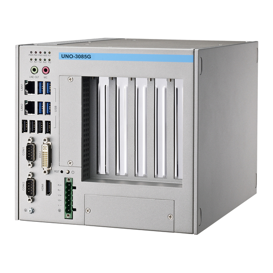
UNO-3000G Series
Intel Core i7/Celeron®
Processors Embedded
Automation Computers, with 3/5
PCI(e) Extension Slots
Table of
Contents
Previous
Page
Next
Page
1
2
3
4
5
Advertisement
Table of Contents
Need help?
Do you have a question about the UNO-3000G Series and is the answer not in the manual?
Ask a question
Questions and answers
Related Manuals for Advantech UNO-3000G Series
Desktop Advantech UNO-3084 User Manual
Core 2 duo embedded automation computer with one pci express and three pci slot extensions (80 pages)
Desktop Advantech UNO-3072L User Manual
Celeron m/ pentium m embedded automation computer with two pci-slot extensions (64 pages)
Desktop Advantech UNO-3074 User Manual
Celeron m/ pentium m embedded automation computer with four pci slot extensions (80 pages)
Desktop Advantech UNO-3072LA User Manual
Intel atom embedded automation computer with two pci slot extensions (64 pages)
Desktop Advantech UNO-3074A User Manual
Intel dual core atom embedded automation computer with two/four pci slot extensions (84 pages)
Desktop Advantech UNO-3072A User Manual
Intel dual core atom embedded automation computer with two/four pci slot extensions (84 pages)
Desktop Advantech UNO-3200G Series User Manual
Intel skylake-h core processors embedded automation pc, with 2x pci(e)/ pci extension slots (50 pages)
Desktop Advantech UNO-3283G User Manual
Intel 6th gen. core i processors embedded automation pc, with 2 or 4 pcie/ pci extension slots (52 pages)
Desktop Advantech UNO-3285C User Manual
Intel 6th gen. core i processors embedded automation pc, with pcie/pci extension slots (44 pages)
Desktop Advantech UNO-3083G User Manual
Intel core i7/celeron processors embedded automation computers, with 3/5 pci(e) extension slots (50 pages)
Desktop Advantech UNO-3072 User Manual
Celeron m/ pentium m embedded automation computer with two pci slot extensions (82 pages)
Desktop Advantech UNO-4683 User Manual
Intel core i7 dual core automation computer with 6xlan, 2xcom, 3 expansion slots (62 pages)
Desktop Advantech UNO-2272G User Manual
Palm size automation computer (28 pages)
Desktop Advantech UNO-1483G Series User Manual
Embedded automation, computer with intel core i processor, 4 x gbe, 3 x mpcie, 1 pcie (optional pci), dp/vga (38 pages)
Desktop Advantech UNO-2372G-J1 Series User Manual
Intel celeron j3455 small form factor modular box platform with 2x gbe, 4x usb, 4x com, 2x mpcie, hdmi, and dp (62 pages)
Desktop Advantech UNO-137 User Manual
Intel atom e3940 processor automation computer, with 2x lan, 2x com, 4x usb, 2x dp, 8x dio, 1x mpcie, and 1x m.2 (58 pages)
This manual is also suitable for:
Uno-3085g
Uno-3083g
Uno-3073g
Uno-3075gl
Uno-3075g
Uno-3073gl
Table of Contents
Print
Rename the bookmark
Delete bookmark?
Delete from my manuals?
Login
Sign In
OR
Sign in with Facebook
Sign in with Google
Upload manual
Upload from disk
Upload from URL


Need help?
Do you have a question about the UNO-3000G Series and is the answer not in the manual?
Questions and answers