
Related Manuals for Nice Elero ExitSafe 28 388.0001


Summary of Contents for Nice Elero ExitSafe 28 388.0001
- Page 1 ExitSafe 28 388.0001 Operating instructions Keep for future use. The system is only fully ready for operation after it has been charged for eight hours from the mains. 18 123.4701_EN_0322...
- Page 2 Translation from the original German version. All other documents in diff erent languages are translations of the original version. All rights reserved in the event of registration of patents, working models or design patents. 2 | EN elero GmbH...
-
Page 3: Table Of Contents
Contents Introduction .........5 Manufacturer contact details ..... 5 Symbols and warnings ......5 Safety instructions .......6 Target group ..........6 Intended use ..........6 Installation and commissioning ....7 System description ......8 System design ........... 8 Usable drives ..........9 Delivery condition ........ - Page 4 Operation ..........21 Individual and master control ....21 Priority individual or master control ..21 Signalling ..........22 Automatic retraction of the blind ....23 Push-button mode or maintained mode .. 23 Wire breakage recognition ...... 24 Shutdown and restart ......24 Additional information ......
-
Page 5: Introduction
Introduction This information for use describes the special features of the ExitSafe system that are required for installation. Follow these instructions to ensure proper and safe use. Retain for future use. Manufacturer contact details elero GmbH Maybachstr. 30 73278 Schlierbach Telephone: +49 (0)7021 9539-0 Email: info@elero.de... -
Page 6: Safety Instructions
CAUTION Danger with a low level of risk, possibly resulting in minor injuries. ATTENTION Danger, possibly resulting in damage to property. Safety instructions Target group This document is primarily intended for use by electri- cians, technicians and engineers with experience in the design, installation, commissioning and maintenance of building technology. -
Page 7: Installation And Commissioning
WARNING ExitSafe ExitSafe may not be used in escape rou- tes and primary rescue routes in accordance with the Model Building Regulation (MBO). Do not use in locations where failure or malfunction • could result in the obstruction of an escape route or a primary rescue route. -
Page 8: System Description
WARNING Risk of injury, damage to the ExitSafe and damage to the area surrounding the ExitSafe as a result of improper electrical connections. The electrical connection may only be conducted by • qualifi ed personnel. Only perform work on the electrical connection if it •... -
Page 9: Usable Drives
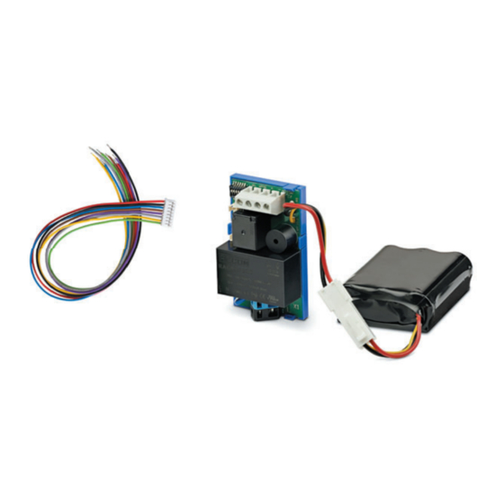
3.1.1 Control module (ExitSafe-S) The drive, mains supply, battery pack and all the com- mand initiators required are connected to the ExitSafe-S control module. The control module also contains the DIP switches used to set the ExitSafe system. The control module evaluates these DIP switches and the connected command initiators and controls the drive accordingly. -
Page 10: Delivery Condition
The end positions for the blind are set directly on the respective drive (not with elero 230 V assembly cable). The drives draw their power exclusively from the battery pack. The 230 V power supply is used exclusively to charge the battery pack. -
Page 11: Electrical Connection
Electrical connection WARNING Risk of injury, damage to the ExitSafe and dama- ge to the area surrounding the ExitSafe due to improper electrical connections. The electrical connection may only be conducted by • qualifi ed personnel. Only perform work on the electrical connection if it •... - Page 12 Terminal connection diagram VarioTec-868 DC The terminals at the signal input of the Exit Safe S are required exclusively for the power supply of the VarioTec-868 DC. Command devices, interlocked push buttons Figure 1: Connection diagram 12 | EN elero GmbH...
-
Page 13: Technical Data
Wire breakage recognition Alarm / smoke detector: i nput with wire break detection Coding: DIP 6: on DIP 1: on Figure 2: Wire breakage detection Technical data Electrical data Electrical data Power supply input 230 V AC, 50 Hz Max. power consumption for input 5.5 W Output voltage motor terminals 8.4 to 12 V DC... -
Page 14: Ambient Conditions
Electrical data Output voltage supply of control elements 8.4 to 12 V DC Rated current supply control elements 50 mA Battery type Li-Ion, 18650, 3S1P Rated voltage battery pack 10.8 V Nominal capacity of the battery pack 3,400 mAh Recommended charging voltage 12 V DC Recommended charge current 700 mA... -
Page 15: Electrical Connections
Mechanical data Control module (ExitSafe-S) weight 60 g Battery pack (ExitSafe-A) dimensions 70 x 55 x 20 mm Battery pack (ExitSafe-A) weight 168 g Electrical connections The ExitSafe is supplied with power of 230 V AC via the spring clamps (X1) on the control module. Designation Assignment External conductor... - Page 16 The ExitSafe is controlled by potential-free contact com- mand initiators. They are connected to the connector strip (X3) on the control module. Control elements that need to be supplied even in the event of a failure in the mains supply can also be connected to this connector strip.
-
Page 17: Settings
No. Wire Designation Assignment colour + 8.4 to 12 V DC supply of control elements Table 3: Assignment control elements Insulate the wires not required against contact. Do not plug the control lines into the printed circuit board until they have been wired. Settings The ExitSafe-S control module has six DIP switches to set the functions listed in Table 4. -
Page 18: Connection And Installation
Function position Function position ON Off | On Individual control has Master control has priority over priority over master individual control control A warning signal will No warning signal will sound sound after two years after two years of operation of operation or or 500 charging cycles of the 500 charging cycles... - Page 19 WARNING The electrical connection may only be conducted by • qualifi ed personnel. Only perform work on the electrical connection if it • has been disconnected from the power supply. Observe the charge status of the battery pack. • Note the technical data for the device. •...
-
Page 20: Commissioning
3. Connect the drive cable to the four-pole screw terminal of the control module using the original connection. The sense of rotation of the drive can be adjusted by exchanging the cables at the UP and DOWN terminals. 4. Connect the mains supply to the two spring clamps on the control module. -
Page 21: Installation In Installation Box
6. Check all required functions when the mains supply is switched off . Installation in installation box • Use the installation box as a double box in fl ush-mounted, surface-mounted or cavity wall version Operation • Single input with interlocked push button / switch or control unit with potential-free contact. -
Page 22: Signalling
Signalling The ExitSafe control module emits the following audible warnings: Warning signal Meaning and measures 1 x long The battery pack must be replaced. Two years of operation or 500 charging (approx. 1 s). cycles of the battery pack have been reached. -
Page 23: Automatic Retraction Of The Blind
Automatic retraction of the blind When automatic retraction of the blind is activated, ExitSafe will control the UP drive if the charge level of the battery pack has dropped to such an extent that only one complete movement of the drive can be ensured. Automatic retraction of the blind can be set with DIP switch 3. -
Page 24: Wire Breakage Recognition
DIP switch 4 ON & DIP switch 5 ON Delayed maintained mode. If operated briefl y, the drive is activated only briefl y. Only if it is operated for a longer period does control of the drive remain active after the input signal drops. -
Page 25: Additional Information
Additional information • Charging cycles and operating times are recorded by the battery pack itself. For this reason, after replacing the battery pack, no further steps are necessary to set up the control module for the new battery pack. • The drive is always supplied with power from the battery pack. -
Page 26: Replacing The Battery Pack
Replacing the battery pack • Only replace the battery pack (elero 28 388.201) only when it is disconnected from the mains voltage. • The type designation of the new accumulator must match the accumulator to be replaced. • Disconnect and connect it with the necessary care for all components. -
Page 27: Information For Use For The Operation Of The Device
Website: www.elero.de WEEE-Reg.-No. DE 26410414 © elero GmbH 2021 All rights reserved. All copyrighted names and trademarks mentioned (such as product names, logos, business names) are protected for the respective right owners. Information for use for the operation of the device Download the operating instructions for the elero ExitSafe using the QR code...
Need help?
Do you have a question about the Elero ExitSafe 28 388.0001 and is the answer not in the manual?
Questions and answers