
Related Manuals for Jet BD-11G


Summary of Contents for Jet BD-11G
- Page 1 OPERATING MANUAL LATHE BD-11G Original: Operating Instructions Parts List JPW (Tool) AG Tämperlistrasse 5 CH-8117 Fällanden Switzerland Phone +41 44 806 47 48 +41 44 806 47 58 www.jettools.com 50000915M 2017-03...
- Page 2 Déclaration de Conformité CE Product / Produkt / Produit: Metal Lathe Die Metall - Dreher Tour de métal BD-11G Brand / Marke / Marque: Manufacturer / Hersteller / Fabricant: JPW (Tool) AG, Tämperlistrasse 5, CH-8117 Fällanden Schweiz / Suisse / Switzerland We hereby declare that this product complies with the regulations Wir erklären hiermit, dass dieses Produkt der folgenden Richtlinie entspricht Par la...
- Page 3 Do not operate the machine under the influence of drugs, In addition to the safety requirements contained in these alcohol or any medication. Be aware that medication can operating instructions and your country’s applicable change your behaviour. regulations, you should observe the generally recognized technical rules concerning the operation of metal machines.
-
Page 4: Table Of Contents
Table of contents 1. Safety 1.1 Safety warnings (warning notes) ………………………………………………………………………………6 1.1.1 Classification of hazards ……………………………………………………………………………..6 1.1.2 Other pictograms………………………………………………………………………………………… 7 1.2 Proper use ………………………………………………………………………………………………………. 8 1.3 Possible dangers caused by the machine…………………………………………………………………..8 1.4 Qualification of personnel…………………………………………………………………………………..9 1.4.1 Target group……………………………………………………………………………………………..9 1.4.2 Authorised personnel………………………………………………………………………………….10 1.4.3 Obligations of the operator………………………………………………………………………..10 1.4.4 Obligations of the user…………………………………………………………………………... - Page 5 3.5.3 Run test………………………………………………………………………………………………..19 3.5.4 Power connection…………………………………………………………………………………..19 3.5.5 Functional test…………………………………………………………………………………………20 3.6 Change gears…………………………………………………………………………………………………20 3.6.1 Assembly of gears changing……………………………………………………………………..20 3.6.2 Table of the gear wheels…………………………………………………………………………..21 4. Design and function 4.1 Construction features………………………………………………………………………………………..21 4.2 Lathe bed………………………………………………………………………………………………....22 4.3 Headstock……………………………………………………………………………………………………..22 4.4 Feed gear……………………………………………………………………………………………………….22 4.5 Apron…………………………………………………………………………………………………………..22 4.6 Tailstock…………………………………………………………………………………………………..22 5.
- Page 6 6.4.1 Spare parts list of top slide…………………………………………………………………………..32 6.5 Exploded view of cross slide………………………………………………………………………………..33 6.5.1 Spare parts list of cross slide………………………………………………………………………..34 6.6 Exploded view of apron………………………………………………………………………………………35 6.6.1 Spare parts list of apron……………………………………………………………………………...36 6.7 Exploded view of lathe bed…………………………………………………………………………………..37 6.7.1 Spare parts list of lathe bed………………………………………………………………………….38 6.8 Exploded view of feed gear………………………………………………………………………………….39 6.8.1 Spare parts list of feed gear…………………………………………………………………………40 6.9 Exploded view of headstock………………………………………………………………………………...
-
Page 7: Safety
Dear Customer, Many thanks for the confidence you have shown in us with the purchase of your new JET-machine. This manual has been prepared for the owner and operators of a JET BD-11 Operating Manual Lathe to promote safety during installation, operation and maintenance procedures. -
Page 8: Classification Of Hazards
ALWAYS KEEP THIS DOCUMENT CLOSE TO THE LATHE FOR FUTURE REFERENCE. 1.1 Safety warnings (warning notes) 1.1.1 Classification of hazards We classify the safety warnings into various levels. The table below gives an overview of the classification of symbols (pictograms) and warnings for the specific danger and its (possible) consequences. Alarm Pictogra Definition/Consequences... -
Page 9: Proper Use
1.2 Proper Use WARNING! Improper use of the lathe will endanger personnel, will endanger the machine and other material property of the operator, may affect proper operation of the machine. The machine is designed and manufactured to be used in environments where there is no potential danger of explosion. -
Page 10: Qualification Of Personnel
If the lathe is used and maintained by personnel who are not duly qualified, there may be a risk resulting from incorrect operation or unsuitable maintenance. INFORMATION All personnel involved in assembly, commissioning, operation and maintenance must be duly qualified, follow this operating manual. -
Page 11: Authorised Personnel
In the event of improper use there may be a risk to personnel, there may be a risk to the machine and other material property, correct functioning of the lathe may be affected. 1.4.2 Authorised personnel WARNING! Incorrect use and maintenance of the machine constitutes a danger for personnel, objects and the environment. -
Page 12: Emergency Stop Button
Stop the lathe immediately if there is a failure in the safety device or if it is not functioning for any reason. It is your responsibility! If a safety device has been activated or has failed, the lathe must only be used when Ь... -
Page 13: Prohibition, Warning And Mandatory Labels
CAUTION! Only operate the lathe using this key. 1.6.4 Prohibition, warning and mandatory labels INFORMATION All warning labels must be legible. Check them regularly. 1.7 Safety check Check the lathe at least once per shift. Inform the person responsible immediately of any dam- age, defect or change in operating function. -
Page 14: Safety During Operation
For certain work individual protection gear is required. Protect your face and eyes: During all work, and specifically work during which your face and eyes are exposed to hazards, a safety helmet with a face guard should be worn. Use protective gloves when lifting or handling pieces with sharp edges. Wear safety shoes when fitting, dismantling or transporting heavy components. -
Page 15: Using Lifting Equipment
Place a warning sign on the machine. WARNING! Before reconnecting the machine, make sure that the change- over switch on the lathe is in the "o" position 1.10.2 Using lifting equipment WARNING! Use of unstable lifting and suspension gear that might break under load can cause very serious injuries or even death. -
Page 16: Technical Data Power Connection
L = length; W = width; H= height; D= depth The specifications in this manual were current at time of publication, but because of our policy of continuous improvement, JET reserves the right to change specifications at any time and without prior notice, without incurring obligations. -
Page 17: Environmental Conditions
Environmental conditions BD-11G Temperature 5 - 35 °C Humidity 25 - 80 % Operating material BD-11G Feed gear Mobilgear 627 or equivalent oil Bright steel parts and lubricating Non-corrosive lubricating oil Change gears Chain oil (spray box) 2.1 Emissions The level of noise emitted by the lathe is less than 70 dB(A). -
Page 18: Storage
3.3 Storage ATTENTION! Improper storage may cause important parts to be damaged or destroyed. Store packed or unpacked parts only under the intended environmental conditions. Consult JPW (Tool) AG if the lathe and accessories have to be stored for a period of over three months or under different environmental conditions to those given here. -
Page 19: Installation Drawing
3.4.4 Installation drawing BD-11 ATTENTION! Tighten the fastening screws on the lathe only until it is firmly secured and cannot move during operation. If the fastening screws are too tight and the foundation is uneven, the bed of the lathe may break. 3.5 First use WARNING! Personnel and equipment may be endangered if the lathe is first used by inexpert per- sonnel. -
Page 20: Cleaning And Greasing
3.5.1 Cleaning and greasing Remove the anticorrosive agent applied to the machine for transport and storage purposes. We recommend the use of stove distillate. Do not use any solvents, thinners or other cleaning agents which could corrode the varnish on the machine. Follow the specifications and indications of the manufacturer of the cleaning agent. -
Page 21: Functional Test
We recommend you to use an FI protected switch sensitive to AC/DC. FI protected switches sensitive to AC/DC (RCCB, type B are adequate for 1 phase and 3phase fed frequency con- verters (driving regulator). An FI protected switch type AC (only for alternating current (AC) is not appropriate for fre- quency converters. FI protected switches type AC are no longer used. -
Page 22: Design And Function
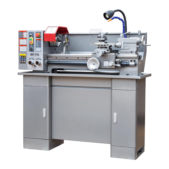
4. Design and function The machine is a universal lathe. It has been designed and manufactured for straight turning and facing round or regularly formed three-, six- or twelve-square workpieces in metal, plastics or similar materials. The hollow work spindle enables you to clamp longer workpieces with a diameter of up to 25 mm. The speed is regulated by repositioning a V-belt on pulleys. -
Page 23: Lathe Bed
Lead screw for thread-cutting or feed for straight turning with change gear set Adjustable tailstock for taper turning 4.2 Lathe bed The lathe bed integrates the headstock and the driving unit, for attaching the apron and lead- screw and for guiding the lathe saddle and tailstock. -
Page 24: Control And Indicating Elements
5.2 Control and indicating elements 5.2.1 BD-11G Lathe 5.3 Control elements 5.4 Toolholder Clamp the turning tool into the toolholder. The tool must be clamped firmly and with the least possible overhang in order to absorb well and reliably the cutting force generated during the chip formation. -
Page 25: Tool Angle
5.4.2 Tool angle ATTENTION! The tool must be clamped with its axis perpendicular to the axis of the work- piece. If it is clamped at an angle, the tool may be sucked into the workpiece. 5.5 Lathe chuck The workpieces must be clamped firmly and securely onto the lathe before they are machined. The clamp should be tight enough to ensure that the workpiece is moved cor- rectly, but not so tight that it is damaged or deformed. -
Page 26: Changing The Speed Range
Unplug the shockproof plug from the mains. Unscrew the two fastening screws. Remove the protective cover. 5.6.2 Changing the speed range Loosen the nut on the tension pulley holder and release the tension of the V-belt. Lift the V-belt into the corresponding position. O Depending on the speed selected, the V-belt will have to be lifted directly onto the motor pulley or onto the pulley of the primary transmission. -
Page 27: Engaging Lever
Immobilise the quadrant with the locking screw. Attach the protective cover of the headstock and reconnect the machine to the power supply. 5.7.3 Engaging lever O The automatic longitudinal feed and the feed for thread-cutting are activated and deactivat- ed using the engaging lever. -
Page 28: Replacing The Clamping Jaws On The Lathe Chuck
Do not clamp any workpieces that exceed the permitted chucking capacity of the lathe chuck. The clamping force of the chuck is too low if its capacity is exceeded. Also, the jaws may come loose. Incorrect Correct 5.10.1 Replacing the clamping jaws on the lathe chuck The clamping jaws and the three-jaw chuck are equipped with numbers. -
Page 29: Coolant
5.11.2 Coolant Friction during the cutting process causes high temperatures at the cutting edge of the tool. The tool should therefore be cooled during the cutting process. Cooling the tool with a suitable cooling lubricant ensures better working results and a longer edge life of the cutting tool. INFORMATION Use a water-soluble and non-pollutant emulsion as a cooling agent. -
Page 30: Restarting
WARNING! Only carry out work on the lathe if it has been unplugged from the mains power supply. 6.1.2 Restarting Before restarting run a safety check. WARNING! Before connecting the machine you must check that there is no danger for personnel and the lathe is undamaged. -
Page 32: Exploded View Of Top Slide
6.4 Exploded view of top slide... -
Page 33: Spare Parts List Of Top Slide
6.4.1Spare part list of top slide Index NO Parts NO. Description Size BD11TS-1 Clamping handle BD11TS-3 Clamping nut quadruple tool holder BD11TS-4 Washer BD11TS-6 Quadruple tool holder BD11TS-5 Hex socket head screwDIN 912 M8×35 BD11TS-7 Gib top slide BD11TS-8 Top slide BD11TS-9 Threaded bolt tool holder BD11TS-10... -
Page 34: Exploded View Of Cross Slide
6.5 Exploded view of cross slide... -
Page 35: Spare Parts List Of Cross Slide
6.5.1 Spare parts list of cross slide Index NO Parts NO. Description Size BD11CS-21 Slide bearing BD11CS-25 Lever BD11CS-26 Handle BD11CS-27 Clamping bolt BD11CS-28 Spring BD11CS-29 Steel ball BD11CS-30 Back clamp BD11CS-31 Before clamp BD11CS-32 Hex socket head screw DIN 912 M8X30 BD11CS-33 Hex socket head screw DIN 912... -
Page 36: Exploded View Of Apron
6.6 Exploded view of apron... -
Page 37: Spare Parts List Of Apron
6.6 Spare parts list of apron Index NO Parts NO. Description Size BD11AP-40 Oil nipple BD11AP-71 Apron BD11AP-72 Handwheel bed slide BD11AP-73 Lever handwheel BD11AP-74 Clamping bolt BD11AP-75 Toothed wheel combination BD11AP-76 Retaining ring BD11AP-77 Retaining pedestal BD11AP-78 Hex socket head screw DIN 912 M5×25 BD11AP-79 Thrust bearing... -
Page 38: Exploded View Of Lathe Bed
6.7 Exploded view of lathe bed... -
Page 39: Spare Parts List Of Lathe Bed
6.7 Spare parts list of lathe bed Index NO Parts NO. Description Size BD11LB-201 Bush BD11LB-202 Tailstock spindle BD11LB-203 Key DIN 6885 - A 3 x 3 x 10 BD11LB-204 Clamping handle BD11LB-205 Handle seat BD11LB-206 Clamping lever BD11LB-207 Threaded pin - M5 x 12 BD11LB-208 Lubricating nipple BD11LB-209... -
Page 40: Exploded View Of Feed Gear
6.8 Exploded view of feed gear... -
Page 41: Spare Parts List Of Feed Gear
6.8.1 Spare parts list of feed gear Index NO Parts NO. Description Size BD11FG-301 Lock washer Φ12 BD11FG-302 Gear wheel BD11FG-303 Lock washer Φ12 BD11FG-304 Shaft C BD11FG-305 Lock washer BD11FG-306 Gear wheel BD11FG-307 Feather key 4×30 BD11FG-308 Feather key 4×60 BD11FG-309 Shaft A... -
Page 42: Exploded View Of Headstock
6.9 Exploded view of headstock... -
Page 43: Spare Parts List Of Headstock
6.9.1 Spare parts list of headstock Pos. Parts NO. Name Size BD11HS-401 Chaaracteristics plate BD11HS-402 Fastening screw M4×10 BD11HS-403 Protective cover of thread rod BD11HS-404 Nut DIN439 BD11HS-405 Knurl nut BD11HS-406 Work spindle BD11HS-407 Feather key DIN 6885 8×45 BD11HS-408 Ring BD11HS-409 Bearing... -
Page 44: Exploded View Of Change Gear
6.10 Exploded view of change gear... -
Page 45: Spare Parts List Of Change Gear
6.10 Spare parts list of change gear Index NO Parts NO. Description Size CG-501 Oil nipple CG-502 Hex socket head screw DIN 912 M8×35 CG-503 Change gear rail CG-504 Bearing Pedestal CG-505 Hex socket head screw DIN 912 M5×10 CG-506 Change gear CG-507 Change gear... -
Page 46: Wiring Diagram
6.11 Wiring Diagram BD-11 (230V) - Page 47 6.11 Spare parts list BD-11G (230V) Pos. Designation Model Quantity Note MAGNETIC CONTACTOR KJD17GF F-O-R SWITCH ZH-A CONTACTOR LC1K0910 TRANSFORMER 230V/24V/20VA TRANSFORMER 230V-24V/20VA Optional EMERGENCY STOP LAY5 GEAR GUARD SWITCH QKS8 CHUNK GUARD SWITCH LXW5-11Q1 LIGHT SWITCH KCD1-101 Optional WORK LIGHT...
-
Page 48: Standard Accessories List
Standard Accessories List for BD-11G Part NO. Name Specification oil gun hexagon wrench 3/4/5/6/8 double end spanner 8-10/12-14/17-19 chuck spanner steady center follow center reverse chuck 3 jaws Ф125mm painting can handle change gears 45/50/60/60/65/70T synchronized counter puuley 240L075(on lathe)
Need help?
Do you have a question about the BD-11G and is the answer not in the manual?
Questions and answers