Jet BDB-1340A Operation And Maintenance Instructions
Belt drive bench lathe, 13x40-inch
Hide thumbs
Also See for BDB-1340A:
- Parts list (47 pages) ,
- Owner's manual (20 pages) ,
- Assembly instructions (4 pages)
Table of Contents
Advertisement
Quick Links
This .pdf document is bookmarked
Operation and Maintenance Instructions
Belt Drive Bench Lathe, 13x40-inch
Model BDB-1340A
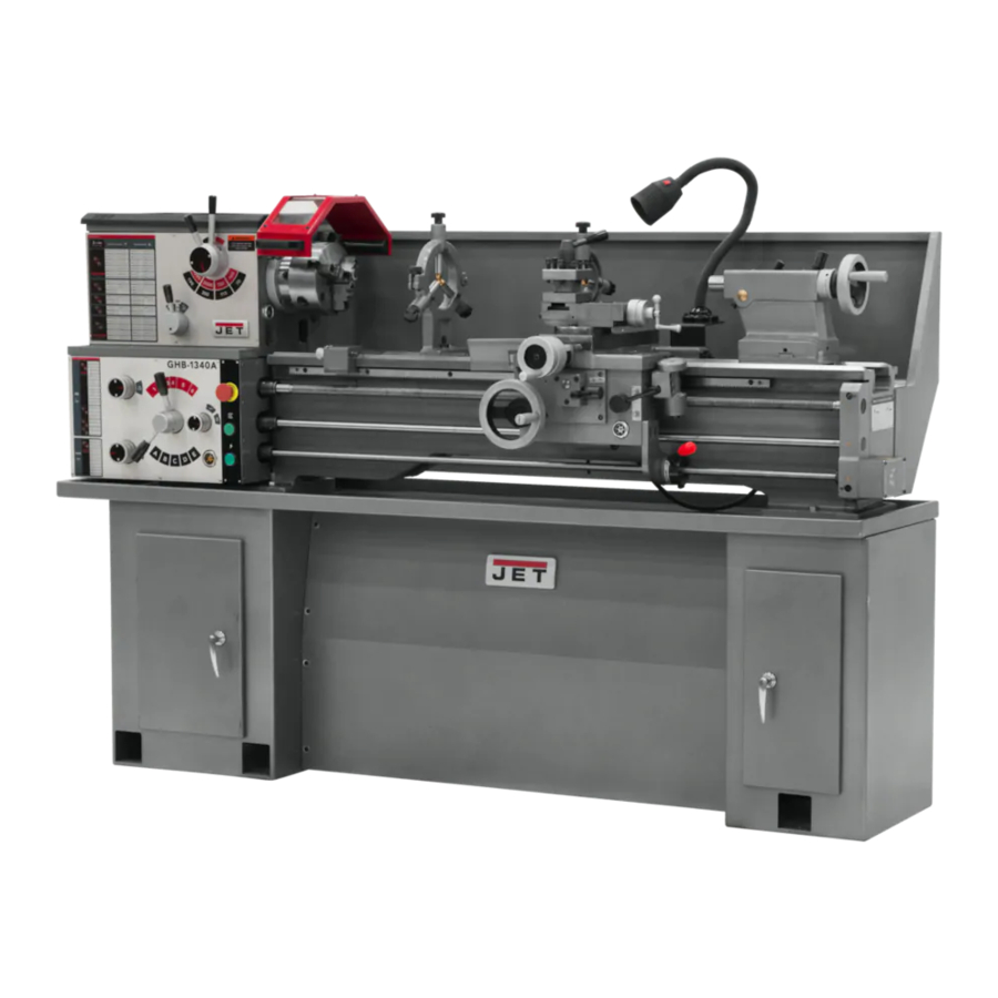
(shown with optional 321443AK stand)
For Parts List and Electrical Diagrams, see document M-321357A
JET
427 New Sanford Road
LaVergne, Tennessee 37086
Part No. M-321360A
Ph.: 800-274-6848
Revision H 05/2016
www.jettools.com
Copyright © 2014 JET
Advertisement
Chapters
Table of Contents

Related Manuals for Jet BDB-1340A


Summary of Contents for Jet BDB-1340A
- Page 1 Belt Drive Bench Lathe, 13x40-inch Model BDB-1340A (shown with optional 321443AK stand) For Parts List and Electrical Diagrams, see document M-321357A 427 New Sanford Road LaVergne, Tennessee 37086 Part No. M-321360A Ph.: 800-274-6848 Revision H 05/2016 www.jettools.com Copyright © 2014 JET...
-
Page 2: Warranty And Service
JET warrants every product it sells against manufacturers’ defects. If one of our tools needs service or repair, please contact Technical Service by calling 1-800-274-6846, 8AM to 5PM CST, Monday through Friday. Warranty Period The general warranty lasts for the time period specified in the literature included with your product or on the official JET branded website. •... -
Page 3: Table Of Contents
Table of Contents Warranty and Service ..........................2 Table of Contents ............................ 3 Warning ..............................3 Specifications ............................5 Dimensions of optional stand (p/n 321443AK) ..................6 Assembly ..............................6 Contents of the Shipping Container ...................... 6 ... - Page 4 11. Do not place hands near the chuck while the machine is operating. 12. Make all machine adjustments or maintenance with the machine unplugged from the power source. 13. Remove adjusting keys and wrenches. Form a habit of checking to see that keys and adjusting wrenches are removed from the machine before turning it on.
-
Page 5: Specifications
Shipping Weight (approx.) ......................1,280 lbs. The above specifications were current at the time this manual was published, but because of our policy of continuous improvement, JET reserves the right to change specifications at any time and without prior notice, without incurring obligations. -
Page 6: Dimensions Of Optional Stand (P/N 321443Ak)
Dimensions of optional stand (p/n 321443AK) To purchase this optional stand for the BDB-1340A Lathe, contact your dealer or call JET customer service. Cross Point Screwdriver Flat Head Screwdriver Assembly Key for Cam Locks Operating Instructions Contents of the Shipping Container... -
Page 7: Uncrating And Clean-Up
Machine is heavy! Use an appropriate lifting device and use extreme caution when moving the machine to its final location. Failure to comply may cause serious injury. Uncrating and Clean-Up 1. Finish removing the wooden crate from around the lathe. 2. -
Page 8: Chuck Preparation (Three Jaw)
Chuck Preparation (Three Jaw) Read and understand all directions for chuck preparation! Failure to comply may cause serious injury and/or damage to the lathe! Note: Before removing the chuck from the spindle, place a way board across the bedways under the chuck. 1. -
Page 9: Lubrication
Lubrication Lathe must be serviced at all lubrication points and all reservoirs filled to operating level before the lathe is placed into service. Failure to comply may cause serious damage to the lathe. 1. Headstock - Oil must be up to indicator mark in both oil sight glasses (A, Fig. - Page 10 5. Apron - Oil must be up to indicator mark in oil sight glass (A, Fig. 8). Top off with Mobil DTE® Oil Heavy Medium. Fill by removing oil plug (C, Fig. 8). After the first three months of operation, drain oil completely (drain is on the bottom of the apron) and refill with Mobil DTE®...
-
Page 11: Electrical Connections
Failure to comply may cause serious injury and/or damage machinery property. The BDB-1340A bench lathe is rated at 2HP, 1PH, 230V only. Confirm that power available at Figure 11 the lathe's location is the same rating as the lathe. Make sure the lathe is properly grounded. - Page 12 Apron The apron (A, Fig. 13) is mounted to the carriage. In the apron a half nut is fitted. The half nut gibs can be adjusted from the outside. The half nut is engaged by use of a lever. Quick travel of the apron is accomplished by means of a bed-mounted rack and pinion, operated by a hand wheel on the front of the apron.
-
Page 13: Controls
Controls 1. Main On-Off Switch (A, Fig. 14) – Power is off in the “0” position and on in the “I” position. 2. Feed Direction Selector (B, Fig. 15) – Arrows above the handle indicate saddle travel direction when the chuck is rotating in the forward direction or counter-clockwise as viewed from the front of the chuck. - Page 14 11. Longitudinal Traverse Handwheel (A, Fig. 17) – Rotate handwheel clockwise to move the apron assembly toward the tailstock (right). Rotate the wheel counter-clockwise to move the apron assembly toward the headstock (left). 12. Feed Selector (B, Fig. 17) – Push lever to the left and down to activate the crossfeed function.
-
Page 15: Adjustments
22. High-Low Speed Selector (A, Fig. 19) - Push toward the rear of the machine for the high-speed range and pull toward the front for the low speed range. 23. Lock Pin for Back Gear (B, Fig. 20) – For high-speed operation, pull out pin and turn pin 90°... -
Page 16: Change Gear Replacement
Change Gear Replacement Note: The 32T x 127T x 48T gears are installed in the end gear compartment when delivered from the factory. This combination will cover most inch feeds and threads under normal circumstances. The additional gears found in the toolbox are used for some metric threads and feeds. -
Page 17: Thread And Feed Chart
Thread and Feed Chart F E E D I N / R E V TRANSVERSE LONGITUDINAL LEVER POSITIONS 0.0073 0.0025 0.0018 0.0006 0.0020 0.0007 0.0081 0.0028 0.0030 0.0122 0.0010 0.0042 0.0033 0.0133 0.0011 0.0046 0.0035 0.0139 0.0012 0.0048 0.0037 0.0146 0.0050 0.0013 0.0041... - Page 18 T H R E A D I N G C H A R T A T T E N T I O N Red circles represent stacked gears T.P.I 0.45 0.50 0.75 0.90 1.25 1.50 1.75 A T T E N T I O N Red circles represent stacked gears 1.80 2.00...
-
Page 19: Automatic Feed Operation And Feed Changes
Automatic Feed Operation and Feed Changes 1. Move forward/reverse selector (A, Fig. 25) up or down depending on desired direction. 2. Set the selector handle (B, Fig. 26) to the “3” position and turn knob (C, Fig. 26) counter-clockwise so the arrow is pointing up to start the feed rod rotating. -
Page 20: Compound Rest Adjustment
Compound Rest Adjustment Follow the same procedure as for the cross slide adjustment. Tailstock Adjustment If the handle will not lock the tailstock securely, use the following procedure: 1. Lower handle to the unlocked position. 2. Slide tailstock to an area that will allow you to reach under the tailstock. - Page 21 5. Using a micrometer, measure the bar stock next to the chuck and at the end. measurement should be the same. 6. If the measurements are not the same and adjustment is required, loosen the four bolts that hold the headstock to the bed. Do not loosen completely;...
- Page 22 Parts List and Electrical Diagrams For Lathe models BDB-1340A, GHB-1340A, GHB-1440A (GHB-1340A shown) For GHB-1340A/1440A Operating Instructions, see document M-321357A-1 For BDB-1340A Operating Instructions, see document M-321360A 427 New Sanford Road LaVergne, Tennessee 37086 Part No. M-321357A Ph : 800-274-6848 Revision J 05/2016 www.jettools.com...
- Page 23 ······················ Replacement parts ········································································································ 3 1.0 ·················· BDB-1340A Headstock Assembly I – Exploded View···························································· 4 1.1 ·················· BDB-1340A Headstock Assembly I – Parts List ································································ 5-6 2.1 ·················· BDB-1340A Headstock Assembly II – Exploded View ··························································· 7 2.2 ·················· BDB-1340A Headstock Assembly II – Parts List ·································································· 8 3.1 ··················...
-
Page 24: Replacement Parts
Replacement parts To order parts or reach our service department , call1-800-274-6848 Monday through Friday (see our website for business hours , www.jettools.com) Having the Model Number and Serial Number of your machine available when you call will allow us to serve you quickly and accurately... -
Page 25: Bdb-1340A Headstock Assembly I - Exploded View
1.0 BDB-1340A Headstock Assembly I – Exploded View... -
Page 26: Bdb-1340A Headstock Assembly I - Parts List
1.1 BDB-1340A Headstock Assembly I – Parts List Index Part Description Size 1 ....04101BG ....Headstock Casting ..................1 10 .... TS-1482021 ....Hex Socket Cap Screw ........... M6x12 ......4 11 .... 04501A ..... Inlet Plug ......................2 13 .... - Page 27 1.1 BDB-1340A Headstock Assembly I – Parts List Index Part Description Size 139 ········ BDB1340A-18703 ······ Emergency Stop Housing(serial #1604B1614A and higher) ·············· 1 140 ········ BDB-SB1 ················· Emergency Stop(serial #1604B1614A and higher) ZB2-BS54C ········· 1 Plain Washer (serial #1604B1614A and higher)6mm ······················· 6 141 ········...
-
Page 28: Bdb-1340A Headstock Assembly Ii - Exploded View
2.1 BDB-1340A Headstock Assembly II – Exploded View... -
Page 29: Bdb-1340A Headstock Assembly Ii - Parts List
2.2 BDB-1340A Headstock Assembly II – Parts List Index Part Description Size 2 ....TS-1503051 ....Hex Socket Cap Screw .......... M6x22 ......4 3 ....BB-30212 ....Taper Roller Bearing ..........60x110x22 ....1 4 ....BDB1340-H4 ..... Oil Seal ..............PG60x80x12 ....1 5 .... -
Page 30: Bdb-1340Aheadstockassemblyiii - Exploded View
3.1 BDB-1340A Headstock Assembly III – Exploded View... -
Page 31: Bdb-1340Aheadstockassemblyiii - Parts List
3.2 BDB-1340A Headstock Assembly III – Parts List Index Part Description Size 8 ....TS-1524021 ....Set Screw ..............M8x10 ......1 15-1 ..TS-1540061 ....Nut ................M8 ......... 1 44 .... 04704 ......Eccentric Shaft ....................1 45 .... -
Page 32: Ghb-1340A/1440A Headstock Assembly I - Exploded View
4.1 GHB-1340A/1440A Headstock Assembly I – Exploded View... -
Page 33: Ghb-1340A/1440Aheadstockassemblyi - Parts List
4.2 GHB-1340A/1440A Headstock Assembly I – Parts List Index Part Description Size 7 ....GHB1340A-02101G .. Gear Box Main Casting (GHB-1340A only) ..........1 ....GHB1440A-02101G .. Gear Box Main Casting (GHB-1440A only) ..........1 9 ....04109 ......Shift Lever ...................... 1 10 .... - Page 34 4.2 GHB-1340A/1440A Headstock Assembly I – Parts List Index Part Description Size ....LM000209 ....Headstock Label (GHB-1340A only)(serial #16043259A and higher) ..1 ....GHB1440A-02301-15 Headstock Label (GHB-1440A only)(serial #16013258A and lower) ..1 ....LM000212 ....Headstock Label (GHB-1440A only)(serial #16043259A and higher) ..1 155 ..
-
Page 35: Ghb-1340A/1440A Headstock Assembly Ii - Exploded View
5.1 GHB-1340A/1440A Headstock Assembly II – Exploded View... -
Page 36: Ghb-1340A/1440A Headstock Assembly Ii - Parts List
5.2 GHB-1340A/1440A Headstock Assembly II – Parts List Index Part Description Size 4 ....04104Z ...... Rear Cover ..................... 1 5 ....04105 ......Pulley ......................1 6 ....GHB1340-4106 ..Plug ........................ 1 25 .... 04209 ......Gear ................. 2m43T ......1 26 .... -
Page 37: Ghb-1340A/1440A Headstock Assembly Iii - Exploded View
6.1 GHB-1340A/1440A Headstock Assembly III – Exploded View... -
Page 38: Ghb-1340A/1440A Headstock Assembly Iii - Parts List
6.2 GHB-1340A/1440A Headstock Assembly III – Parts List Index Part Description Size 1 ....GHB1340A-02103N... Collar ......................1 2 ..... 04102 ......Collar (serial #07061677A and lower) ............1 ....C0632A-02117A ..Collar (serial #07061678A and higher) ............1 3 ..... -
Page 39: Bed Assembly I - Exploded View
7.1 Bed Assembly I – Exploded View... -
Page 40: Bed Assembly I - Parts List
15 .... 32A1106 ....Collar ......................1 16 .... GHB1340A-1701 ..Lead Screw .............. GHB-1340A ....1 ....BDB1340A-1701 ..Lead Screw .............. BDB-1340A ..... 1 17 .... 321728 ...... Key ......................... 1 18 .... 321706 ...... Collar ......................1 19 .... - Page 41 7.2 Bed Assembly I – Parts List Index Part Description Size 50 .... TS-1502021 ....Socket Head Cap Screw .......... M5x10 ......4 51 .... TS-1503061 ....Hex Socket Cap Screw ..........M6x25 ......8 53 .... TS-1540061 ....Hex Nut ..............M8 ......... 4 54A ..
-
Page 42: Bed Assembly Ii - Exploded View
8.1 Bed Assembly II – Exploded View... -
Page 43: Bed Assembly Ii - Parts List
....GHB1340A-01701BJG….Oil Plate .............. GHB-1340A ....1 ....C0632-01727G ..Oil Plate ..............GHB-1440A ....1 ....BDB1340A-01701B ... Oil Plate(serial #1204B1274A and lower) ... BDB-1340A ....1 ....BDB1340A-01701BJ . Oil Plate(serial #1205B1275A and lower) ... BDB-1340A ....1 .... -
Page 44: Gear Assembly I - Exploded View
9.1 Gear Assembly I – Exploded View... -
Page 45: Gear Assembly I - Parts List
99 .... GHB1340A-05503 ..Rubber Mat (GHB-1340A only) (serial #16013258A and lower) ....1 ....GHB1440A-05503 ..Rubber Mat (GHB-1440A only) (serial #16013258A and lower) ....1 ....BDB1340A-05503 ..Rubber Mat (BDB-1340A only) (serial #1509B1613A and lower) ....1 100 ..TS-1502041 ....Socket Set Screw............. M5x16 ......2 101 .. - Page 46 117 ..GHB1340A-G117 ..Oil Sight Glass(GHB-1340A,serial #10052363A and lower).12mm ..1 ....GHB1340A-G117 ..Oil Sight Glass(GHB-1440A,serial #08040097C and lower).12mm ..1 ....GHB1340A-G117 ..Oil Sight Glass(BDB-1340A,serial #1008B1083A and lower)M27x1.5 ..1 ....GHB1340A-160M ..Oil Sight Glass(GHB-1340A,serial #10102364A and higher)M27x1.5 ..1 ....
-
Page 47: Gear Assembly Ii - Exploded View
10.1 Gear Assembly II – Exploded View... -
Page 48: Gear Assembly Ii - Parts List
10.2 Gear Assembly II – Parts List Index Part Description Size 21 .... 32A5113 ....Cover ......................1 22 .... 32A5503 ....Gasket ......................1 23 .... 32A5712 ....Shaft ....................... 1 24 .... 32A5710A ....Gear ................. 2.5m30T,20T ....1 25 .... -
Page 49: Gear Assembly Iii - Exploded View
11.1 Gear Assembly III – Exploded View... -
Page 50: Gear Assembly Iii - Parts List
11.2 Gear Assembly III – Parts List Index Part Description Size 21 .... 32A5113 ....Cover ......................1 22 .... 32A5503 ....Gasket ......................1 50 .... 32A5115 ....End Cover...................... 1 52 .... 32A5718A ....Gear ................ 2.5m30T,15T ....1 53 .... -
Page 51: Apron Assembly I - Exploded View
12.1 Apron Assembly I – Exploded View... -
Page 52: Apron Assembly I - Parts List
52 ... 06551 ......Oil Sight Glass(GHB-1340A,serial #10052363A and lower) ........06551 ......Oil Sight Glass(GHB-1440A,serial #08040097C and lower) ........06551 ......Oil Sight Glass(BDB-1340A,serial #1008B1083A and lower) ........GHB1340A-160M…..Oil Sight Glass(GHB-1340A,serial #10102364A and higher) M27x1 5 .. -
Page 53: Apron Assembly Ii - Exploded View
13.1 Apron Assembly II – Exploded View... -
Page 54: Apron Assembly Ii - Parts List
13.2 Apron Assembly II – Parts List Index Part Description Size 2 ··········· 06102G ···················· Handwheel ······································ ··········································· 1 5A ········· 06105A ···················· Hub ················································ ··········································· 1 10 ·········· 06510 ······················ Index Ring ······································· ··········································· 1 11 ·········· Z06111 ···················· Cover ·············································· ··········································· 1 12 ··········... -
Page 55: Apron Assembly Iii - Exploded View
14.1 Apron Assembly III – Exploded View 14.2 Apron Assembly III – Parts List Index Part Description Size 5 ....Z06105G ....Threading Dial Body ..................1 6 ....06206 ......Washer ......................1 35 .... 06233 ......Threading Dial Shaft ..................1 38 .... -
Page 56: Micro Carriage Stop Assembly - Exploded View
15.1 Micro Carriage Stop Assembly – Exploded View 15.2 Micro Carriage Stop Assembly – Parts List Index Part Description Size 1 ....GHB1340A-01707 ..Dial ......................... 1 2 ....GHB1340A-MS02 ..Pin ................B3x6 ......... 1 3 ....GHB1340A-01716 ..Axle ........................ 1 4 .... -
Page 57: Top Slide, Tool Post, Saddle, And Cross Slide I - Exploded View
16.1 Top Slide, Tool Post, Saddle, and Cross Slide I – Exploded View... -
Page 58: Top Slide, Tool Post, Saddle, And Cross Slide I - Parts List
69 .... GHB1340-69T ... Ball Bearing ....................2 88 .... GHB1340-88 ..... Oil Ball ..............6 ........3 ....GHB1340-TSA ..Top Slide Assembly w/o Tool Post (For GHB-1340A/BDB-1340A) ....1 ....GHB1440A-TSA ..Top Slide Assembly w/o Tool Post (GHB-1440A Only) ........1... -
Page 59: Top Slide, Tool Post, Saddle, And Cross Slide Ii - Exploded View
17.1 Top Slide, Tool Post, Saddle, and Cross Slide II – Exploded View... -
Page 60: Top Slide, Tool Post, Saddle, And Cross Slide Ii - Parts List
Part Description Size 1 ..... 07101 ......Slide(GHB-1340A,serial #07061685A and lower) ........1 (BDB-1340A,serial #0706B0764A and lower) ........ 1 ....GHB-1340A-04101A .. Slide(GHB-1340A,serial #07061686A and higher) ........1 (BDB-1340A,serial #0707B0765A and higher) ....... 1 (for GHB-1440A) ....GHB-1340A-04101AG….Slide ......................1 2 .... - Page 61 88 .... GHB1340-88 ..... Oil Ball ..............6 ........1 91 .... GHB1340A-04789E ... Stop Pin(GHB-1340A,serial #07061686A and higher) ......1 (BDB-1340A,serial #0707B0765A and higher) ......1 (for GHB1440A) ................1 92 ... GHB-EL ..... Machine Lamp ............JC34A ......1 93 ....
-
Page 62: Tailstock Assembly I - Exploded View
18.1 Tailstock Assembly I – Exploded View... -
Page 63: Tailstock Assembly I - Parts List
18.2 Tailstock Assembly I – Parts List Index Part Description Size 1 ....Z08101G ....Casting ......................1 2 ....Z08102G ....Flange Cover....................1 3 ....08103G ...... Hand Wheel ....................1 7 ....08202 ......Quill ........................ 1 8 .... -
Page 64: Tailstock Assembly Ii - Exploded View
Description Size 4 ....08104 ......Clamp Plate ....................1 5 ....08105G ..... Base (For GHB-1340A/BDB-1340A) ............. 1 ....C0636A-03104G ..Base (For GHB-1440A) ................. 1 15 .... 08211 ......Collar ......................1 16 .... 08212 ......Screw (For GHB-1340A/BDB-1340A) ............1 .... -
Page 65: Follow Rest - Exploded View
8 ....TS-1540041 ....Nut ................M6 ......... 2 9 ....TS-1523051 ....Set Screw ..............M6x16 ......2 10 .... 10104G ...... Base Casting (For GHB-1340A/BDB-1340A) ..........1 ....C0636A-10104G ..Base Casting (For GHB-1440A) ..............1 11 .... -
Page 66: Steady Rest - Exploded View
21.1 Steady Rest – Exploded View... -
Page 67: Steady Rest - Parts List
11 .... GHB1340-11SR ..Bolt ................M6x30 ......1 12 .... 10206 ......Pivot Bolt......................1 13 .... 10102G ..... Base Casting (For GHB-1340A/BDB-1340A) ..........1 ....C0636A-10101G ..Base Casting (For GHB-1440A) ..............1 14 .... TS-1540081 ....Nut ................M12 ....... 1 15 .... -
Page 68: Ghb-1340A/1440Achuck Guard Assembly - Exploded View
22.1 GHB-1340A/1440A Chuck Guard Assembly – Exploded View 22.2 GHB-1340A/1440A Chuck Guard Assembly – Parts List Index Part Description Size ....GHB-CGA ....Chuck Guard Assembly(index #1 thru 21) ..........1 1 ....GHB1340A-19701EG Protection Guard.................... 1 2 .... -
Page 69: Additional Parts (Not Shown)
Size ············ BDB1340-QS1 ··········· Main Power Switch (BDB-1340A Only) ············································· 1 ············ BDB1340-QS1-A ········ Faceplate for Power Switch (BDB-1340A Only) ·································· 1 ············ BDB1340-QS1-B ········ Knob for Power Switch (BDB-1340A Only) ········································ 1 ············ 321320 ····················· Motor (2HP,1Ph,60HZ 230V only for GHB-1340A/1440A) ···················· 1 ············... -
Page 70: Electrical Schematic - Ghb-1340A/1440A
25.1 Electrical Schematic – GHB-1340A/1440A 25.2 Electrical Schematic Parts List – GHB-1340A/1440A Index Part Description Size 1 ·········· GHB-SB1 ··············· Emergency Stop ···························· ZB2-BS54C ······················· 1 2 ·········· GHB-SB2 ··············· Jog Button ···································· XB2-EA131 ························ 1 3 ·········· GHB-HL ················· Power Indicator Light ······················ XB7-EVF3LC ····················· 1 4 ··········... -
Page 71: Electrical Schematic - Bdb-1340A
26.1 Electrical Schematic – BDB-1340A 26.2 Electrical Schematic Parts List – BDB-1340A Index Part Description Size 1 ·········· BDB-SB1 ················ Emergency Stop ···························· ZB2-BS54C ······················· 1 2 ·········· BDB-KA1 ················ Relay ·········································· JZC3-40d ·························· 1 3 ·········· BDB-KM1 ··············· A.C.Contactor ······························· GSC1-D2501 ····················· 1 4 ··········... -
Page 72: Ghb-1340A/1440Awiringphoto
27.0 GHB-1340A/1440A Wiring Photo 28.0 BDB-1340A Wiring Photo...
Need help?
Do you have a question about the BDB-1340A and is the answer not in the manual?
Questions and answers