
Related Manuals for Jet BD-8VS


Summary of Contents for Jet BD-8VS
- Page 1 BD-8VS OPERATING MANUAL LATHE Original: Operating Instructions Parts List JPW (Tool) AG Tämperlistrasse 5 CH-8117 Fällanden Switzerland Phone +41 44 806 47 48 +41 44 806 47 58 www.jettools.com 50000911M 2017-12...
- Page 2 Déclaration de Conformité CE Product / Produkt / Produit: Metal Lathe Die Metall - Dreher Tour de métal BD-8VS Brand / Marke / Marque: Manufacturer / Hersteller / Fabricant: JPW (Tool) AG, Tä mperlistrasse 5, CH-8117 Fä llanden Schweiz / Suisse / Switzerland We hereby declare that this product complies with the regulations Wir erklä...
-
Page 3: Table Of Contents
(Original) 1.0 About this Manual This manual is provided by JET, covering the safe operation and maintenance procedures for a JET Model BD-8VS Metal Lathe. This manual contains instructions on installation, safety precautions, general operating procedures, maintenance instructions and parts breakdown. The machine has been designed and constructed to provide consistent, long-term operation if used in accordance with the instructions as set forth in this document. -
Page 4: Important Safety Instructions
Do not use this machine for other than its intended use. If used for other purposes, JET disclaims any real or implied 19. Keep visitors a safe distance from the work area. Keep warranty and holds itself harmless from any injury that children away. - Page 5 Familiarize yourself with the following safety notices used in this manual: WARNING: This means that if precautions are not heeded, it may result in serious, or possibly even fatal, injury. CAUTION: This means that if precautions are not heeded, it may result in minor injury and/or possible machine damage.
-
Page 6: Designated Use And Limitations To Use
3.1 Designated use and limitations to use The machine is designed for turning and drilling machinable metal and plastic materials only. The workpiece must allow to safely be loaded, supported and clamped. The machine is intended for indoor use. The protection rating of the electrical installation is IP 54. To avoid tipping, the machine must be bolted down with anchor bolts. -
Page 7: Specifications
L = length; W = width; H= height; D= depth The specifications in this manual were current at time of publication, but because of our policy of continuous improvement, JET reserves the right to change specifications at any time and without prior notice, without incurring obligations. - Page 8 4.1 Spindle nose mounting: Figure 4-1: Spindle nose mounting 4.2 Anchor bolt hole pattern: Figure 4-2: Lathe Bed anchor bolt pattern WARNING: To avoid tipping, the machine must be bolted down with anchor bolts (not provided).
-
Page 9: Machine Description
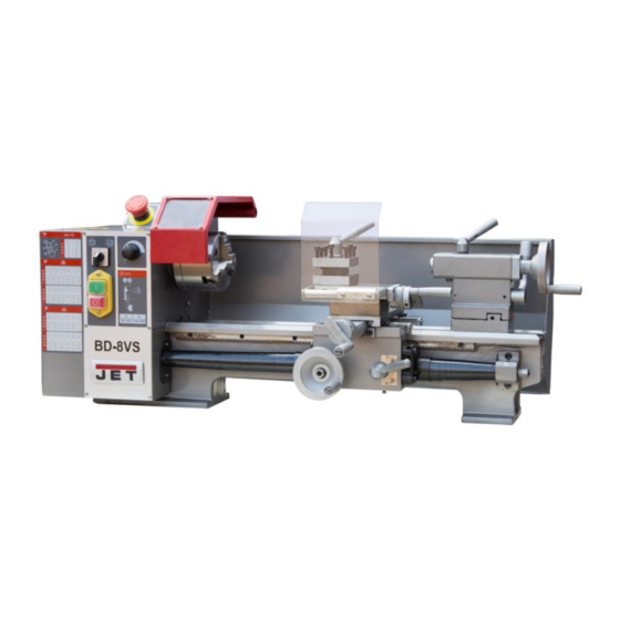
5.0 Machine Description Figure 5-1: Machine description Figure 5-2: Machine description A ..........Change gear quadrant B ...............Pulley cover N ..........Spindle power ON/OFF C ..............Headstock O .......... Spindle forward/reverse D ..........Chuck and chuck guard P ........Variable speed select knob E ........ -
Page 10: Setup And Assembly
Cabinet stand (Optional) Failure to comply may result in serious injury. Coolant facility (Optional) The BD-8VS Metal Lathes are rated at 1~230V, PE, 50Hz power Machine lamp(Optional) supply. The machines come with a plug designed for use on a 100mm 3-jaw chuck circuit with a grounded outlet. -
Page 11: Extension Cords
the outlet is properly grounded. Do not modify the plug Remove the pulley cover (C, Fig 5-1) to change the belt provided with the tool. position. The green/yellow conductor is the equipment-grounding conductor. If repair or replacement of the electric cord or plug is necessary, do not connect the equipment-grounding 8.2 Change gear setup conductor to a live terminal. -
Page 12: Taper Turning With Tailstock
8.3 Taper turning with tailstock 8.5 Three jaw universal chuck Mount the work piece fitted with the drive dog between With this universal chuck, cylindrical, triangular and hexagonal centres. The drive dog is driven by the face plate. stock may be clamped (Fig 8-5). Lubricate the tailstock centre with grease to prevent tip from overheating. -
Page 13: Live Centre
8.7 Live centre (Optional) The live centre (Fig 8-7) is mounted in ball bearings. Its use is highly recommended for speeds above 500 RPM. Figure 8-7: Live centre To eject the live centre, fully retract the tailstock quill. Figure 8-9: Follow rest Set the fingers (2) snug but not overly tight. -
Page 14: Operating Controls
9.0 Operating Controls 10.2 Chucking Refer to Figure 9-1: Do not exceed the max speed of the work holding device. N ........... Spindle power ON/OFF Jaw teeth and scroll must always be fully engaged. Otherwise chuck jaws may break and fly off in rotation (Fig 10-1). O .......... -
Page 15: Cutting Tool Setup
10.3 Cutting Tool Setup 10.5 Manual turning The cutting angle is correct when the cutting edge is in line Apron travel (S, Fig 10-6), cross travel (T) and top slide travel with the centre axis of the work piece. Use the point of the (U) can be operated for longitudinal and cross feeding. -
Page 16: Thread Cutting
11.0 User-Maintenance 10.7 Thread cutting Threading is performed in multiple passes with a threading tool. WARNING: Each depth of cut should be about 0,2mm and become less for Before any intervention on the machine, disconnect it from the finishing passes. electrical supply, pull the mains plug. -
Page 17: Troubleshooting
Dispose all packaging material in an environmental friendly manner. Dispose coolant in an environmentally friendly manner. Your appliance contains valuable materials which can be recovered or recycled. Please leave it at a specialized institution. 14.0 Available Accessories Refer to the JET price list. -
Page 18: Replacement Parts
15.0 Replacement Parts BD-8VS Assembly Breakdown -1... - Page 19 BD-8VS Parts List for Breakdown -1 Index Part Description Size Qty. 101 ..BD7VS-1 ......HEXAGON SOCKET HEAD CAP SCREW DIN 912 ...M5×25 ......4 . 102 ..BD7VS-2 ......SPLIT WASHER DIN 127 ........5 ......... 4 . 103 ..BD7VS-103 ......D.C.MOTOR ..................... 1 .
- Page 20 BD-8VS Assembly Breakdown -2...
- Page 21 BD-8VS Parts List for Breakdown -2 Index Part Description Size Qty. 201 ..BD7VS-201 ......HANDLE ....................1 . 202 ..BD7VS-202 ......TIGHTENING NUT QUADRUPLICATE TOOL HOLDER ........1 203 ..BD7VS-203 ......WASHER QUADRUPLICATE TOOL HOLDER ..........1 .
- Page 22 BD-8VS Assembly Breakdown -3...
- Page 23 BD-8VS Parts List for Breakdown -3 Index Part Description Size Qty. 301 ..BD7VS-39 ......SET SCREW DIN 914 ..........M8×8 ......1 302 ..BD7VS-302 ......FIXING NUT HANDWHEEL ........M8, H=16mm ..... 1 303 ..BD7VS-303 ......HANDWHEEL LATHE SLIDE ..............1 304 ..
- Page 24 BD-8VS Assembly Breakdown -4...
- Page 25 BD-8VS Parts List for Breakdown -4 Index Part Description Size Qty. 401 ----- BD7VS-401 ......LOCKING WAHSER ................... 2 402 ----- BD7VS-402 ......TOOTHED WHEEL ..........Z=75 ......1 403 ----- BD7VS-403 ......TOOTHED WHEEL ..........Z=30 ......1 404 ----- BD7VS-404 ......COLLAR AXLE SHAFT ................2 405 ----- BD7VS-405 ......
- Page 26 BD-8VS Assembly Breakdown -5...
- Page 27 BD-8VS Parts List for Breakdown -5 Index Part Description Size Qty. 501 ..BD7VS-501 ......CLAMPIND LEVER TAIL-STOCK ..............1 502 ..BD7VS-502 ......CLAMPING LEVER TAILSTOCK SLEEVE ............. 1 503 ..BD7VS-503 ......SPLIT TAPER SOCKET TAILSTOCK SLEEVE ..........1 504 ..
- Page 28 BD-8VS Assembly Breakdown -6...
- Page 29 BD-8VS Parts List for Breakdown -6 Index Part Description Size Qty. 601 ..BD7VS-601 ......SUPPORT ....................1 602 ..GB7085-5-12 ....... SOCKET HD SCREW ..........M5 × 12 mm ....2 603 ..BD7VS-603 ......SHAFT ...................... 1 604 ..
- Page 30 BD-8VS Assembly Breakdown -7...
- Page 31 BD-8VS Parts List for Breakdown -7 Index Part Description Size Qty. 701 ..BD7VS-701 ......SCREW ..................... 5 702 ..BD7VS-702 ......TIGHTENING SCREW ................5 703 ..BD7VS-703 ......SLIDE JAW ....................5 704 ..GB9785-8 ......SPRING WASHER (STD) ........8 ........5 705 ..
- Page 32 BD-8VS Assembly Breakdown -8...
- Page 33 BD-8VS Parts List for Breakdown -8 Index Part Description Size Qty. 801 ..BD7VS-801 ......LEFT STAND ..................... 1 802 ..BD7VS-802 ......CONNECTING PLATE ................1 803 ..GB617086-8 ......HEX NUT .............. M8 ......10 804 ..GB7085-8-16 ....... SOCKET HD SCREW ..........M8 x 16 mm ....10 805 ..
- Page 34 BD-8VS Assembly Breakdown -9...
- Page 35 BD-8VS Parts List for Breakdown -9 Index Part Description Size Qty. 901 ..BD7VS-901 ......NOZZLE ....................1 902 ..BD7VS-902 ......OUTLET PIPE .................... 1 903 ..BD7VS-903 ......RETURNING PIPE ..................1 904 ..BD7VS-904 ......WATER TANK................... 1 905 ..
-
Page 36: Wiring Diagrams
16.0 Wiring Diagrams BD-8VS ……………….1~230V, PE, 50Hz... - Page 37 BD-8VS Electrical Parts List Designation Model Quantity Note Electromagnetic switch KJD17GF Reverse Switch F/R ZH-A EMC Filter NF213A6/02 250VAC 6A Emergency stop ZB2-BE102C Circuit board JYMC-220A-I 230VAC 6.0ADC Potentiometer WX14-12 4K7 Speed display and sensor JD011 5V DC Motor 83ZYT005A FU1,FU2...
Need help?
Do you have a question about the BD-8VS and is the answer not in the manual?
Questions and answers