Table of Contents
Advertisement
Quick Links
Advertisement
Table of Contents

Related Manuals for Jet BDB-919


Summary of Contents for Jet BDB-919
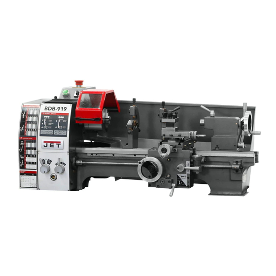
- Page 1 This .pdf document is bookmarked Operating Instructions and Parts Manual 9x19, 9x29-inch Belt Drive Bench Lathes Models BDB-919, -929 427 New Sanford Road LaVergne, Tennessee 37086 Part No. M-321378 Ph.: 800-274-6848 Edition 1 04/2017 www.jettools.com Copyright © 2017 JET...
-
Page 2: Important Safety Instructions
1.0 IMPORTANT SAFETY INSTRUCTIONS 1.1 GROUNDING INSTRUCTIONS 1. All grounded, cord-connected tools: In the event of a malfunction or breakdown, grounding provides a path of least resistance for electric current to reduce the risk of electric shock. This tool is equipped with an electric cord having an equipment-grounding conductor and a grounding plug. -
Page 3: For All Tools As Applicable
Do not use this lathe for other than its intended use. If used for other purposes, JET disclaims any real or implied warranty and holds itself harmless from any injury that may result from that use. - Page 4 22. NEVER STAND ON TOOL. Serious injury could occur if the tool is tipped or if the cutting tool is unintentionally contacted. 23. CHECK DAMAGED PARTS. Before further use of the tool, a guard or other part that is damaged should be carefully checked to determine that it will operate properly and perform its intended function - check for alignment of moving parts, binding of moving parts, breakage of parts, mounting, and any other conditions that may affect its operation.
-
Page 5: Table Of Contents
2.0 Table of Contents 1.0 IMPORTANT SAFETY INSTRUCTIONS ....................... 2 1.1 GROUNDING INSTRUCTIONS ......................... 2 1.2 For all tools as applicable ........................... 3 2.0 Table of Contents ............................5 3.0 Introduction ..............................7 4.0 Specifications ..............................7 5.0 Unpacking ..............................9 5.1 Contents of shipping container ........................ - Page 6 13.17.1 Accessories – Exploded View ......................50 13.17.2 Accessories – Parts List ........................50 13.18.1 BDB-919 Stand #321375 (Optional Accessory) – Exploded View ............ 51 13.18.2 BDB-919 Stand #321375 (Optional Accessory) – Parts List ............. 51 13.19.2 BDB-929 Stand #321377 (Optional Accessory) – Exploded View ........... 52 13.19.2 BDB-929 Stand #321377 (Optional Accessory) –...
-
Page 7: Introduction
If there are any questions or comments, please contact either your local supplier or JET. JET can also be reached at our web site: www.jettools.com. - Page 8 = not applicable The specifications in this manual were current at time of publication, but because of our policy of continuous improvement, JET reserves the right to change specifications at any time and without prior notice, without incurring obligations.
-
Page 9: Unpacking
5.0 Unpacking Open shipping container and check for shipping damage; report any damage immediately to your distributor and shipping agent. Do not discard any shipping material until the Lathe is assembled and running properly. Compare the contents of your container with the following parts list to make sure all parts are intact. Missing parts, if any, should be reported to your distributor. -
Page 10: Setup And Preparation For Operation
Carefully read the grounding instructions on pages 2 and 3. It is recommended that the BDB-919 and BDB-929 Lathes be connected to a dedicated, minimum 25 amp circuit with a circuit breaker or time delay fuse. -
Page 11: Carriage
7.3 Carriage The carriage (Figure 5) is made from high-grade cast iron. The sliding parts are smooth ground. They fit the V on the bed without play. The lower sliding parts can be easily and simply adjusted. The cross slide is mounted on the carriage and moves on a dovetail. -
Page 12: Tailstock
7.5 Tailstock The tailstock (Figure 9) slides on a V-way and can be clamped at any location. The tailstock has a heavy duty spindle with a Morse taper No.2 socket and a graduated scale. The spindle can be clamped at any location with a clamping lever. The spindle is moved with a handwheel at the end of the tailstock. -
Page 13: Controls
8.0 Controls Figure 12 Forward/Reverse Switch 10. Tailstock Spindle Clamping Lever V-Belt Tension Lever 11. Tailstock Locking Lever Longitudinal Travel Handwheel 12. Tailstock Off-Set Adjustment Half-Nut Lever 13. Automatic Feed Lever Cross Slide Handwheel 14. Gear Box Quick Change Lever Top Slide Handwheel 15. -
Page 14: Operation
9.0 Operation 9.1 Tool set-up The cutting angle is correct when the cutting edge is in line with the center axis of the work piece. The correct height of the tool can be achieved by comparing the tool point with the point of the center mounted in the tailstock. -
Page 15: Taper Turning Using Tailstock Off-Set
9.4 Taper turning using tailstock off- Offsetting the tailstock can turn work to side angle of 5º. The angle depends on the length of the workpiece. To off-set the tailstock, loosen locking lever (1, Figure 16), then loosen the front adjusting screw (2) and take up the same amount by tightening the opposite rear adjusting screw until the desired taper has been reached. -
Page 16: Thread Cutting
9.7 Thread Cutting As indicated on the threading charts (see sect. 15.0), several different threads can be cut using the proper combination of gears and settings. When cutting inch threads, the half nut and threading dial (Figure 19) are used to thread in a conventional manner. -
Page 17: Lathe Accessories
10.0 Lathe Accessories 10.1 Three jaw universal lathe chuck Using this universal chuck (Figure 21), round, triangular, square, hexagonal, octagonal, and twelve-cornered stock may be clamped. Note: New lathes have very tight fitting jaws. This is necessary to ensure accurate clamping and long service life. -
Page 18: Steady Rest
Figure 27 10.9 Stand (optional) A steel stand specially designed for this lathe is available from JET (Figure 28). Contact your distributor or JET to order. Stand # 321375 for BDB-919 Lathe. Stand # 321377 for BDB-929 Lathe. -
Page 19: Four-Way Tool Post
10.10 Four-way tool post The four-way tool post is mounted on the top slide and allows for tools to be clamped. Loosen the center clamp handle to rotate any of the four tools into position (Figure 29). Use a minimum of two clamping screws when installing a cutting tool. -
Page 20: Adjustment Of Compound Feed Screw And Float
11.3 Adjustment of compound feed screw and float To adjust the slides on the saddle: Loosen screw (1, Figure 33) and lock nut (2, Figure 33). Adjust the nut until all play has been taken up. Lock the nut (2) with the screw (1). Figure 33 11.4 Cross slide screw Remove the compound slide and adjust screw (1,... -
Page 21: Adjustment Of Half-Nut Guide
11.6 Adjustment of half-nut guide Loosen two nuts (1, Figure 36) on the right side of the apron and adjust the set screws (2, Figure 36) until both half nuts move freely without play. Tighten both nuts. Figure 36 11.7 Replacing the V-belt Remove tension on the V-belt by pulling lever toward front of the machine (Figure 37). -
Page 22: Lubrication Schedule
12.0 Lubrication Schedule (Figures 39 and 40) Note: Lubricate all locations daily. Grease refers to #2 tube grease. Oil refers to 20W machine oil. 1 – 1 to 2 squirts of oil into oil ball on gear hub. 2 – Grease teeth of feed and change gears. 3 –... -
Page 23: Replacement Parts
Non-proprietary parts, such as fasteners, can be found at local hardware stores, or may be ordered from JET. Some parts are shown for reference only, and may not be available individually. -
Page 24: Headstock Assembly - Parts List
25 ....BDB919-025 ....C-Washer..............20mm ......1 26 ....F009921 ....Socket Hd Button Screw .......... M3-0.5X5 ...... 6 27 ....BDB919-027 ....Name Plate w/ speed chart (BDB-919) ............1 ....BDB929-027 ....Name Plate w/ speed chart (BDB-929) ............1 .... -
Page 25: Drive Belt Assembly - Exploded View
13.2.1 Drive Belt Assembly – Exploded View... -
Page 26: Drive Belt Assembly - Parts List
13.2.2 Drive Belt Assembly – Parts List Index No. Part No. Description Size 101 .... BDB919-101 ....Bracket Plate ....................1 102 .... TS-1504041 ....Hex Socket Hd Cap Screw ........M8-1.25X20 ....2 103 .... BDB919-103 ....Belt Pulley Shaft .................... 1 104 .... -
Page 27: Belt Tension Lever - Exploded View
13.3.1 Belt Tension Lever – Exploded View 13.3.2 Belt Tension Lever – Parts List Index No. Part No. Description Size 201 .... BDB919-201 ....Lever Bracket Assembly ................1 202 .... BB-6001ZZ ....Ball Bearing ............. 6001ZZ ......2 203 .... -
Page 28: Change Gears - Exploded View
13.4.1 Change Gears – Exploded View 13.4.2 Change Gears – Parts List Index No. Part No. Description Size 301 .... BDB919-301 ....Bracket......................1 302 .... BDB919-302 ....T-Nut ......................1 303 .... BDB919-303 ....Flat Washer, spcl ................... 2 304 .... -
Page 29: Electrical - Exploded View
13.5.1 Electrical – Exploded View... -
Page 30: Electrical - Parts List
13.5.2 Electrical – Parts List Index No. Part No. Description Size 401 .... BDB919-401 ....Electrical Box ....................1 402 .... BDB919-402 ....Button LAY37(PBC)-C ................... 1 403 .... BDB919-403 ....Switch ZH-A ....................1 404 .... TS-2244122 ....Socket Hd Button Screw .......... M4-0.7X12 ....6 405 .... -
Page 31: Chuck Guard - Exploded View
13.6.1 Chuck Guard – Exploded View 13.6.2 Chuck Guard – Parts List Index No. Part No. Description Size 501 .... TS-1540031 ....Hex Nut ..............M5 ......... 2 502 .... BDB919-502 ....Bracket......................1 503 .... TS-1502021 ....Hex Socket Hd Cap Screw ........M5-0.8x20 ..... 2 504 .... -
Page 32: Gear Box - Exploded View
13.7.1 Gear Box – Exploded View... -
Page 33: Gear Box - Parts List
13.7.2 Gear Box – Parts List Index No. Part No. Description Size 601 .... F005338 ....Hex Socket Hd Cap Screw ........M3-0.5x5 ....... 4 602 .... BDB919-602 ....Graphic Plate ....................1 603 .... BDB919-603 ....Lever ......................2 604 .... - Page 34 Index No. Part No. Description Size 705 .... BDB919-705 ....Gear ................. 12T-1.25M ....1 706 .... BDB919-706 ....Screw ......................1 707 .... TS-1502021 ....Hex Socket Hd Cap Screw ........M5-0.8X10 ....1 708 .... BDB919-708 ....Washer ......................1 709 ....
-
Page 35: Apron I - Exploded View
13.8.1 Apron I – Exploded View... -
Page 36: Apron I - Parts List
13.8.2 Apron I – Parts List Index No. Part No. Description Size 701 .... F010960 ....Socket Hd Flat Screw ..........M6-1.0X8 ...... 2 702 .... BDB919-702 ....Washer ......................2 703 .... AH25C-060 ....Spring Pin ..............4X30mm ....... 1 704 .... -
Page 37: Apron Ii - Exploded View
13.9.1 Apron II – Exploded View 13.9.2 Apron II – Parts List Index No. Part No. Description Size 752 .... BDB919-752 ....Screw ......................1 753 .... TS-1540061 ....Hex Nut ..............M8X1 ......1 754 .... BDB919-754 ....Worm ......................1 755 .... -
Page 38: Saddle And Cross Slide - Exploded View
13.10.2 Saddle and Cross Slide – Exploded View... -
Page 39: Saddle And Cross Slide - Parts List
13.10.2 Saddle and Cross Slide – Parts List Index No. Part No. Description Size 801 .... BDB919-801 ....Saddle ......................1 802 .... BDB919-802 ....Cross Slide ....................1 803 .... BDB919-803 ....Gib ......................... 1 804 .... BDB919-804 ....Nut ......................... 1 805 .... -
Page 40: Compound Slide - Exploded View
13.11.1 Compound Slide – Exploded View... -
Page 41: Compound Slide - Parts List
13.11.2 Compound Slide – Parts List Index No. Part No. Description Size 901 .... BDB919-901 ....Longitudinal Slide ..................1 902 .... BDB919-902 ....Swivel Base ....................1 903 .... BDB919-903 ....Gib ......................... 1 904 .... BDB919-904 ....Clamping Ring ....................1 905 .... -
Page 42: Tailstock - Exploded View
13.12.1 Tailstock – Exploded View... -
Page 43: Tailstock - Parts List
13.12.2 Tailstock – Parts List Index No. Part No. Description Size 1001 ..BDB919-1001 .... Tailstock Ram ....................1 1002 ..BDB919-1002 .... Lead Screw ....................1 1003 ..BDB919-1003 .... Bushing ......................1 1004 ..BDB919-1004 .... Clamp ......................1 1005 .. -
Page 44: Steady Rest - Exploded View
13.13.1 Steady Rest – Exploded View 13.13.2 Steady Rest – Parts List Index No. Part No. Description Size 1101 ..BDB919-1101 .... Rest Casting ....................1 1102 ..BDB919-1102 .... Jaw ........................ 3 1103 ..BDB919-1103 .... Screw ......................3 1104 .. -
Page 45: Follow Rest - Exploded View
13.14.1 Follow Rest – Exploded View 13.14.2 Follow Rest – Parts List Index No. Part No. Description Size 1201 ..BDB919-1201 .... Follow Rest Casting ..................1 1202 ..BDB919-1202 .... Jaw ........................ 2 1203 ..BDB919-1203 .... Screw ......................2 1204 .. -
Page 46: Bd-919 Bed Assembly - Exploded View
13.15.1 BD-919 Bed Assembly – Exploded View... -
Page 47: Bdb-919 Bed Assembly - Parts List
13.15.2 BDB-919 Bed Assembly – Parts List Index No. Part No. Description Size 1301 ..BDB919-1301 .... Bed ........................ 1 1302 ..BDB919-1302 .... Splash Guard ....................1 1303 ..TS-1502021 ....Hex Socket Hd Cap Screw ........M5X10 ......3 1304 .. -
Page 48: Bdb-929 Bed Assembly - Exploded View
13.16.1 BDB-929 Bed Assembly – Exploded View... -
Page 49: Bdb-929 Bed Assembly - Parts List
13.16.2 BDB-929 Bed Assembly – Parts List Index No. Part No. Description Size 1301-1 ..BDB929-1301 .... Bed ........................ 1 1302-1 ..BDB929-1302 .... Splash Guard ....................1 1303 ..TS-1502021 ....Hex Socket Hd Cap Screw ........M5X10 ......3 1304 .. -
Page 50: Accessories - Exploded View
13.17.1 Accessories – Exploded View 13.17.2 Accessories – Parts List Index No. Part No. Description Size 1401 ..BDB919-1401 .... 4-Jaw Chuck Kit ............187mm ......1 1401A .......... 4-Jaw Chuck Body ..................1 1401B ..BDB919-1401B ..4-Jaw Chuck Key ................... 1 1402 .. -
Page 51: Bdb-919 Stand #321375 (Optional Accessory) - Exploded View
Index No. Part No. Description Size ....321375 ...... BDB-919 Stand (#1501 thru 1510) ..............1 1501 ..BDB919-1501 .... Left Stand ..............H:760mm ...... 1 1502 ..BDB919-1502 .... Door Latch Assembly..................2 1503 ..BDB919-1503 .... Stand Plate .............. L:385mm ....... 2 1504 .. -
Page 52: Bdb-929 Stand #321377 (Optional Accessory) - Exploded View
1507 ..TS-149105 ....Hex Cap Screw ............M10x35 ......2 1508 ..TS-1550041 ....Flat Washer ............. 6mm ......8 1509 ..TS-1503021 ....Hex Socket Hd Cap Screw ........M6X10 ......8 1510 ..JET-92 ....... JET Logo (not shown) ..........92x38mm ...... 1... -
Page 53: Wiring Diagram For Bdb-919,929 Lathes
14.0 Wiring diagram for BDB-919,929 Lathes... -
Page 54: Speed And Threading Charts
15.0 Speed and threading charts... -
Page 55: Warranty And Service
Accessories; Shop Tools; Warehouse & Dock products; Hand Tools; Air Tools NOTE: JET is a division of JPW Industries, Inc. References in this document to JET also apply to JPW Industries, Inc., or any of its successors in interest to the JET brand. - Page 56 427 New Sanford Road LaVergne, Tennessee 37086 Phone: 800-274-6848 www.jettools.com...
Need help?
Do you have a question about the BDB-919 and is the answer not in the manual?
Questions and answers