Jet BDB-1340A Owner's Manual
Belt drive lathe
Hide thumbs
Also See for BDB-1340A:
- Operation and maintenance instructions (72 pages) ,
- Parts list (47 pages) ,
- Assembly instructions (4 pages)
Table of Contents
Advertisement
Advertisement
Table of Contents

Related Manuals for Jet BDB-1340A


Summary of Contents for Jet BDB-1340A
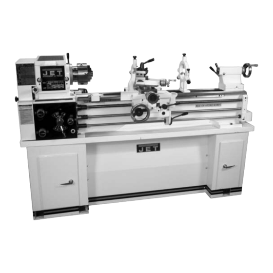
- Page 1 OWNER'S MANUAL BDB-1340A Belt Drive Lathe (shown with optional stand) WMH TOOL GROUP Industrial Metalworking Products Division 300 S. Hicks Rd. Chicago, IL 60067 Ph: 1-888-594-5866 Fax: 1-800-626-9676 E-mail: jet@wmhtoolgroup.com www.wmhtoolgroup.com M-321360A 08/02...
-
Page 2: Warranty
This manual has been prepared for the owner and operators of a JET Belt Drive Lathe. Its purpose, aside from machine operation, is to promote safety through the use of accepted correct operating and maintenance procedures. Completely read the safety and maintenance instructions before operating or servicing the machine. -
Page 3: Warnings
13. Keep children and visitors away. WARNING visitors should be kept a safe distance from Read and understand the entire contents of the work area. this manual before attempting set-up or operation of this mill/drill. 14. Make the workshop child proof. padlocks, master switches, and remove 1. -
Page 4: Specifications
Specifications: BDB-1340A Stock Number..........................321360A Capacities: Swing Over Bed........................... 13" Swing Over Cross Slide ........................7-25/32" Swing Through Gap........................18-3/4" Length of Gap..........................8-1/8" Distance Between Centers........................40" Headstock: Hole Through Spindle ........................1-1/2" Spindle Nose ............................. D1-4 Taper in Spindle Nose ........................MT-5 Spindle Taper Adapter ........................ -
Page 5: Table Of Contents
Table of Contents Warranty..............................2 Warnings ..............................3 Specifications ............................4 Table of Contents ............................ 5 Contents of the Shipping Container......................6 Uncrating and Clean-Up........................... 7 Chuck Preparation ........................... 8 Lubrication............................9-10 Electrical Connections ........................... 11 General Description .......................... 11-12 Controls............................ -
Page 6: Contents Of The Shipping Container
Contents of the Shipping Container 1. Lathe 1. Steady Rest (mounted on lathe) 1. Follow Rest (mounted on lathe) 1. 6" Three Jaw Chuck (mounted on lathe) 1. 8" Four Jaw Chuck 1. 12" Face Plate (strapped to container) 3. Cam Locks 3. -
Page 7: Uncrating And Clean-Up
WARNING Machine is heavy! Use an appropriate lifting device and use extreme caution when moving the machine to its final location. Failure to comply may cause serious injury! Uncrating and Clean-Up 1. Finish removing the wooden crate from around the lathe. 2. -
Page 8: Chuck Preparation
Chuck Preparation (Three Jaw) WARNING Read and understand all directions for chuck preparation! Failure to comply may cause serious injury and/or damage to the lathe! Note: Before removing the chuck from the spindle, place a way board across the bedways under the chuck 1. -
Page 9: Lubrication
Lubrication CAUTION Lathe must be serviced at all lubrication points and all reservoirs filled to operating level before the lathe is placed into service! Failure to comply may cause serious damage to the lathe! 1. Headstock - Oil must be up to indicator mark in both oil sight glasses (A, Fig. - Page 10 5. Apron - Oil must be up to indicator mark in oil sight glass (A, Fig. 6). Top off with Mobil Oil Heavy Medium. Fill by removing oil plug (B, Fig. 6). After the first three months of operation, drain oil completely (drain is on the bottom of the apron) and refill with Mobil DTE Oil Heavy Medium, or...
-
Page 11: Electrical Connections
Failure to comply may cause serious injury and / or damage to the machinery and property! The BDB-1340A bench lathe is rated at 2HP, 1Ph, 230V only. Confirm power available at the lathe's location is the same rating as the lathe. - Page 12 Apron The apron (A, Fig. 10) is mounted to the carriage. In the apron a half nut is fitted. The half nut gibs can be adjusted from the outside. The half nut is engaged by use of a lever. Quick travel of the apron is accomplished by means of a bed-mounted rack and pinion, operated by a hand wheel on the front of the apron.
-
Page 13: Controls
Controls 1. Main On-Off Switch (A, Fig. 11) - Power is off in the “0” position and on in the “I” position. 2. Feed Direction Selector (B, Fig. 12) - Arrows above the handle indicate saddle travel direction when the chuck is rotating in the forward direction or counter-clockwise as viewed from the front of the chuck. - Page 14 11. Longitudinal Traverse Hand Wheel (A, Fig. 14) - Rotate hand wheel clockwise to move the apron assembly toward the tailstock (right). Rotate the wheel counter- clockwise to move the apron assembly toward the headstock (left). 12. Feed Selector (B, Fig. 14) - Push lever to the left and down to activate the crossfeed function.
-
Page 15: Break-In Procedure
22. High Low Speed Selector (A, Fig. 16) - Push toward the rear of the machine for the high-speed range and pull toward the front for the low speed range. 23. Lock Pin for the Back Gear (B, Fig. 17) - Pull the pin out and turn 90 clockwise to engage the back gear. -
Page 16: Change Gear Replacement
Change Gear Replacement Note: the 32T x 127T x 48T gears are installed in the end gear compartment when delivered from the factory. This combination will cover most inch feeds and threads under normal circumstances. The additional gears found in the toolbox are used for some metric threads and feeds. -
Page 17: Thread And Feed Chart
Thread and Feed Chart... -
Page 18: Automatic Feed Operation And Feed Changes
Automatic Feed Operation and Feed Changes 1. Move forward/reverse selector (A, Fig. 22) up or down depending on desired direction. 2. Set the selector handle (B, Fig. 23) to the “P” position and turn knob (C, Fig. 23) counter-clockwise so the arrow is pointing up to start the feed rod rotating. -
Page 19: Compound Rest Adjustment
Compound Rest Adjustment Follow the same procedure, as the cross slide adjustment. Tailstock Adjustment If the handle will not lock the tailstock securely, use the following procedure: 1. Lower handle to the unlocked position. 2. Slide tailstock to an area that will allow you to reach under the tailstock. -
Page 20: Removing/Installing Gap Section
5. Using a micrometer, measure the bar stock next to the chuck and at the end. measurement should be the same. 6. If the measurements are not the same and adjustment is required, loosen the four bolts that hold the headstock to the bed. Do not loosen completely;...
Need help?
Do you have a question about the BDB-1340A and is the answer not in the manual?
Questions and answers