
Related Manuals for KEB COMBIVERT CONTROL G6 VARAN


Summary of Contents for KEB COMBIVERT CONTROL G6 VARAN
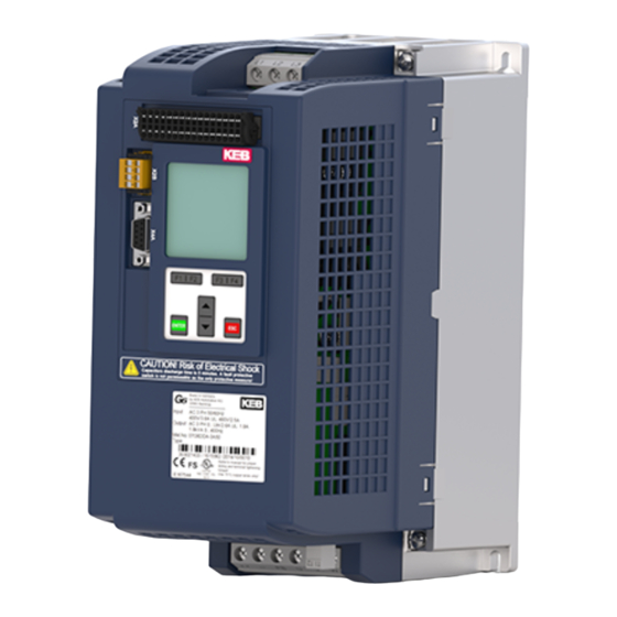
- Page 1 COMBIVERT G6 PROGRAMMING MANUAL | CONTROL G6 VARAN Translation of the original manual Document 20099381 EN 01...
-
Page 3: Preface
PRefACe Preface The described hard- and software are developments of the KEB Automation KG. The enclosed documents correspond to conditions valid at printing. Misprint, mistakes and technical changes reserved. Signal words and symbols Certain operations can cause hazards during the installation, operation or thereafter. -
Page 4: Laws And Guidelines
If applicable, the license terms of this software are contained in the instructions for use. The instructions for use are already available to you, can be downloaded free of charge from the KEB website or can be requested from the respec- tive KEB contact person. -
Page 5: Table Of Contents
TAbLe Of CONTeNTS Table of Contents Preface ..............................3 Signal words and symbols ......................3 More symbols ..........................3 Laws and guidelines ........................4 Warranty and liability ........................4 Support ............................4 Copyright ............................4 Table of Contents ........................... 5 1 basic Safety Instructions ..........6 1.1 Target group ............................. -
Page 6: Basic Safety Instructions
► Read the instructions for use ! ► Observe the safety and warning instructions ! ► If anything is unclear, please contact KEB Automation KG ! 1.1 Target group This instruction manual is determined exclusively for electrical personnel. Electrical per- sonnel for the purpose of this instruction manual must have the following qualifications: •... -
Page 7: Electrical Connection
bASIC SAfeTy INSTRUCTIONS 1.2 electrical connection DANGeR Voltage at the terminals and in the device ! Danger to life due to electric shock ! ► For any work on the unit switch off the supply voltage and secure it against switching on. ►... -
Page 8: Product Description
PRODUCT DeSCRIPTION 2 Product Description 2.1 Product features These instructions for use describe the parameterization of the following devices: Device series: COMBIVERT G6 Hardware: VARAN 2.2 Overview of functions The control provides the following functions: • Hardware-installed supply of digital and analog inputs and outputs •... -
Page 9: Dual Port Memory
DUAL PORT MeMORy 3 Dual Port Memory A Dual Port Memory (DPM) is a RAM memory, whereupon read or write access is pos- sible from two sides simultaneously. The entire bus is treated like a 4GB memory, a defined memory area is assigned to each client.This allows the CPU of the control to access on the participants with simple save, read and write commands. - Page 10 DUAL PORT MeMORy Cmd/MsgID • cccc...command ID 0...invalid 1...read 2...write 3...initialization (all i and m bits are 1) • i…initialization bit (set during initialization command with all the m-bits) Must be sent once after every switch on to transfer the device from status "init"...
-
Page 11: Parameterization Data (Asynchronous Objects)
DUAL PORT MeMORy 3.2 Parameterization data (asynchronous objects) It is not necessary that the COMBIVERT G6 has synchronized to the fieldbus cycle to receive asynchronous requests and respond. The parameter data are communicated via the handshaking shown in chapter „Output process data (manager => client)“. The VARAN master has to write on to the area "acy- clic request" at the DPM. The area "acyclic respond" is filled by the device with valid data and can be read by the master. -
Page 12: Process Data (Isochronous Objects)
DUAL PORT MeMORy Id-Text Name Parameter index fb21 Master write event counter 0x2195 Meaning Number of asynchronous read accesses Type Variable Data length 16 bit Access read / write Coding 0...65535 Standard value: 0 Note 3.3 Process data (isochronous objects) There are 16 bytes of process data available in both directions. -
Page 13: Process Data Mapping
PROCeSS DATA MAPPING 4 Process Data Mapping The setting of the process data assignment can be done in two different ways. One is through the KEB specific parameters (fb10-fb19), on the other hand about the parame- ters (co08, c014) which are defined according to the CAN DS301 profile. After successful adjustment of the process data mapping the process data can be pro- cessed by the G6 device. - Page 14 PROCeSS DATA MAPPING Id-Text Name Parameter index fb11 PD out subindex 0x218B Type Array Subindex 0 Meaning Number of subindices of this object Data length 8 bit Access read Coding Standard value: 8 Note Subindex 1...8 Meaning The value of the subindex determines the parameter set of the selected PD parameter.
- Page 15 PROCeSS DATA MAPPING Id-Text Name Parameter index fb13 PD out type 0x218D Type Array Subindex 0 Meaning Number of subindices of this object Data length 8 bit Access read Coding Standard value: 8 Note Subindex 1...8 Meaning The value specifies the parameter type of the selected PD pa- rameter. Data length 8 bit Access read / write...
- Page 16 PROCeSS DATA MAPPING Id-Text Name Parameter index co08 RPDO1 mapping 0x1600 Type Array Subindex 0 Meaning Sets the number of mapped objects Data length 8 bit Access read / write Coding 0...8 Standard value: 0 Note Successively, no gaps as on the fb-mapping parameters possible. Subindex 1...8 Meaning Describes an object mapping. The index, subindex and the object length are specified...
-
Page 17: Input Process Data (Client => Manager)
PROCeSS DATA MAPPING 4.2 Input process data (client => manager) Id-Text Name Parameter index fb15 PD in index 0x218F Type Array Subindex 0 Meaning Number of subindices of this object Data length 8 bit Access read Coding Standard value: 8 Note Subindex 1...8 Meaning... - Page 18 PROCeSS DATA MAPPING Id-Text Name Parameter index fb17 PD in offset 0x2191 Type Array Subindex 0 Meaning Number of subindices of this object Data length 8 bit Access read Coding Standard value: 8 Note Subindex 1...8 Meaning Specifies the offset of occupancy in the process data field. Posi- tion of the value of the mapped parameter.
- Page 19 PROCeSS DATA MAPPING Id-Text Name Parameter index fb19 PDO-in count 0x2193 Meaning Sets the number of PD-in objects Type Variable Data length 8 bit Access read / write Coding 0...8 Standard value: 0 Note Is automatically set to 0 when changing the parameters fb15...fb18. Id-Text Name Parameter index...
-
Page 20: Synchronization On Varan Fieldbus
SyNCHRONIzATION ON VARAN fIeLDbUS 5 Synchronization on VARAN fieldbus In order to ensure the data consistency when accessing to the dual port memory, the internal calculation cycle must be synchronized to the external VARAN cycle. For this, the external cycle time is defined by the parameter fb25. A PLL shifts the internal calculation grid accordingly. If the synchronization is completed successfully, the syn- chronous operation is shown over the VARAN status LED. - Page 21 SyNCHRONIzATION ON VARAN fIeLDbUS Id-Text Name Parameter index fb27 synchronization state 0x219B Meaning State of synchronization to the fieldbus cycle Type Variable Data length 8 bit Access read Coding 0: off (device not synchronous) 1: on (device synchronous) Standard value: 0 Note Id-Text Name Parameter index fb28 pd access time 0x219C...
-
Page 22: Fieldbus Watchdog
fIeLDbUS WATCHDOG 6 fieldbus Watchdog The fieldbus watchdog is a function in the VARAN control board. It is used to trigger an error or warning in the inverter, if certain events are not cyclically repeated within a cer- tain time. The activation of the watchdog is set by the control card parameters fb04 and fb05. The monitoring time and the at exceeding of the monitoring time executed function is set by parameter in the inverter (pn05, pn06). -
Page 23: Operator Parameters
OPeRATOR PARAMeTeRS 7 Operator Parameters The operator parameters set the configuration of the G6 VARAN control. Furthermore, the software version as well as the current status can be read. Id-Text Name Parameter index os00 operator identifier 0x2080 Meaning Displays the control card type, as well as the software version. Type Variable Data length 32 bit Access read... - Page 24 OPeRATOR PARAMeTeRS Id-Text Name Parameter index os04 diag error count 0x2084 Meaning Specifies the number of errors occurred on the diagnostic inter- face. Type Variable Data length 8 bit Access read / write Coding 0...255 Standard value: 0 Note Id-Text Name Parameter index os05 diagnosis response delay 0x2085 Meaning Sets the minimum response delay time for requests on the diag- nostic interface.
- Page 25 OPeRATOR PARAMeTeRS Id-Text Name Parameter index os07 node ID 0x2087 Meaning This parameter specifies the inverter address for the diagnostic interface (DIN 66019). The parameter is an image of the system parameter Sy06. Type Variable Data length 8 bit Access read / write Coding 0...239 Standard value: 1 Note Id-Text Name...
- Page 26 OPeRATOR PARAMeTeRS Id-Text Name Parameter index os09 PU max invbusy retries 0x2089 Meaning Number of repetitions that are sent on the internal bus from the power module to the controller if it rejects "inverter busy" error. Type Variable Data length 8 bit Access read / write...
- Page 27 OPeRATOR PARAMeTeRS Id-Text Name Parameter index os13 operator state 0x208D Meaning Displays the status of the power unit, as well as the image of the power unit parameter of the control board. Type Variable Data length 8 bit Access read Coding Bit 0 reserved...
- Page 28 OPeRATOR PARAMeTeRS Id-Text Name Parameter index os15 store mode 0x208F Meaning The memory type of non-volatile parameters must be adjusted with this parameter. The parameters will not be stored if the val- ue is "0", the device automatically changes to value "1" after the next "power down".
- Page 29 OPeRATOR PARAMeTeRS Id-Text Name Parameter index os19 safety software version 0x2093 Meaning Displays the software version of the safety module. Type Variable Data length 32 bit Access read Coding 0.0.0.0...255.255.255.255 If no security module is installed, the value "0: no safety function- ality“...
-
Page 30: Light-Emitting Diodes
LIGHT-eMITTING DIODeS 8 Light-emitting Diodes 8.1 Status LeDs of VARAN plugs Link LED Green Lights up when connection consists between two PHYs. Active LED Yellow Lights up when data are received over the VARAN bus. 8.2 Network status LeD The LED located on the top of the device indicates the status of the VARAN client ap- plication. -
Page 31: Revision History
ReVISION HISTORy 9 Revision History Version Date Description 2015-02 Completion series 2015-07 Change to document view. Version not counted up 2019-05 Changed to new KEB CI optic... - Page 32 NOTES...
- Page 33 Room 1709, 415 Missy 2000 725 Su Seo Dong E-Mail: vb.belgien@keb.de Internet: www.keb.de Gangnam Gu 135- 757 Seoul Republic of Korea Tel: +82 2 6253 6771 Fax: +82 2 6253 6770 E-Mail: vb.korea@keb.de KEB South America - Regional Manager brazil Rua Dr.
- Page 34 Automation with Drive www.keb.de KEB Automation KG Suedstrasse 38 32683 Barntrup Tel. +49 5263 401-0 E-Mail: info@keb.de...
Need help?
Do you have a question about the COMBIVERT CONTROL G6 VARAN and is the answer not in the manual?
Questions and answers