
Subscribe to Our Youtube Channel
Related Manuals for KEB C6-COMPACT


Summary of Contents for KEB C6-COMPACT
- Page 1 KEB COMBICONTROL C6-COMPACT INSTRUCTION MANUAL C6-COMPACT II Mat.No. Rev. 00C6NEB-BA00...
- Page 2 KEB reserves the right to change/adapt specifications and technical data without prior notice. The safety and warning directions specified in this manual is not exhaustive. The manual and the information contained in it is made with care. KEB don´t accept a guarantee for misprint or other errors or resulting damages.
-
Page 3: Table Of Contents
Table of Contents Description of the Unit................4 Intended use ......................4 Assembly ........................4 1.3 CE-certifications ....................4 1.4 Unit identification ....................5 Technical data ......................5 Accessory .......................7 Functional Description ................8 Real-time clock ......................8 HSP5/485-interfaces to the inverter/servo axes ..........8 2.2.1 View of the inverter interfaces X1A...X1D for the axes 1..4 ........9 2.2.2 Assignment of the HSP5/485 interfaces ..............9 2.2.3 HSP5 Operator with screw terminal (00F5060-9001) ..........10 2.2.4 HSP5 Operator with RJ45 socket (00F5060-9002) ..........10... -
Page 4: Description Of The Unit
KEB COMBICONTROL C6-COMPACT is a programmable control with direct connection upto four KEB frequency inverters/servo axes of the series F5. The connection to the axes is created as HSP5/485. All axes can be operated directly and synchronously with an inex- pensive operator with this fast, reliable connection. -
Page 5: Unit Identification
(y) = soft option: A = no, B = soft motion Examples: 00C6BA1-AAB0 C6-Compact 4DI/4DO + soft motion 00C6BA1-BAB0 C6-Compact 4DI/4DO + PROFIBUS slave + soft motion 00C6BA1-CAA0 C6-Compact 4DI/4DO + CAN 00C6BA1-DAA0 C6-Compact 4DI/4DO + INTERBUS slave 00C6BD1-ACA0 C6-Compact II 4DI/4DO... - Page 6 Axis interface X1A ... X1D Type HSP5/485 Connector RJ-45, 8-pole, screened Cable Cat5, max. 100 m Speed 38.4…250 kBaud Using Connection to KEB F5 inverter/servo, process data transmission, communication channel Ethernet interfaces X6B, X6C Type IEEE802.3 10/100BaseTx Connector RJ-45, 8-pole, screened Speed 10/100 MBaud...
-
Page 7: Accessory
KEB COMBICONTROL Accessory Operators Material number F5 HSP5/485, screw terminal 00F5060-9001 F5 HSP5/485, RJ45 00F5060-9002 Connection cable Material number Cable RS232 for COMBIVIS 0058025-001D Cable RJ45 open end (for operator -9001), 2,5 m 00F50C3-2025 Patch cable RJ45 (for operator -9002), 5 m... -
Page 8: Functional Description
COMBIVIS or the control program (library „SysTime“). HSP5/485-interfaces to the inverter/servo axes Up to four KEB COMBIVERT F5 can be connected via the terminals X1A to X1D. The connection occurs via reliability RS485 cables, which can be up to 100 m long. A shielded standard cable with RJ-45 connector is used on the control side and appropriate operator on the frequency inverter/servo. -
Page 9: View Of The Inverter Interfaces X1A
KEB COMBICONTROL 2.2.1 View of the inverter interfaces X1A...X1D for the axes 1..4 X1B (axis 2) —— —— X1A (axis 1) X1D (axis 4) —— —— X1C (axis 3) 2.2.2 Assignment of the HSP5/485 interfaces X1A…D Name Description Socket (top view) -
Page 10: Hsp5 Operator With Screw Terminal (00F5060-9001)
KEB COMBICONTROL 2.2.3 HSP5 Operator with screw terminal (00F5060-9001) Name Description TXD- Transmission signal- TXD+ Transmission signal+ RXD- Receive signal- RXD+ Receive signal+ EnTXD- Handshake transmission signal- EnTXD+ Handshake transmission signal+ EnRxD- Handshake receive signal- EnRxD+ Handshake receive signal+ Reference potential... -
Page 11: Adapter Cable Hsp5 Interface Operator
KEB COMBICONTROL 2.2.5 Adapter cable HSP5 interface operator Screw terminal: Color see below C6 PCC Signal TXD+ TXD- GND RXD+ RXD- GND EnTXD+ EnTXD- X1A…H Operator Signal RXD+ RXD- GND TXD+ TXD- GND EnRxD+ EnRxD- Color see below RJ45 connection:... -
Page 12: Voltage Supply And Digital Inputs And Outputs
KEB COMBICONTROL Voltage supply and digital inputs and outputs Figure 2.3 Socket X2 Voltage supply Digital in- and outputs Digital input 0 Digital input 1 + Voltage input (UM) (internally interconnected) Digital input 2 Digital input 3 Digital output 0... -
Page 13: Voltage Supply Of The Control
KEB COMBICONTROL 3. Plug cable into the round slot, that no wires can be seen from the outside. 4. Remove screw driver and check if cables are fixed. 2.3.2 Voltage supply of the control The voltage for supply of the control (US) occurs via terminals X2.9 and X2.10 in accordance with picture 2.3.2 and is electrically insulated from UM. -
Page 14: Voltage Supply For The Inputs And Outputs
KEB COMBICONTROL 2.3.3 Voltage supply for the inputs and outputs The voltage for supply of the digital inputs and outputs (UM) occurs via the terminals X2.1 to X2.8 in accordance with picture 2.3.3 and is electrically insulated from US. Is set in case of overload at one or several outputs. Additionally the OL-LED %IB1 (red) is set. -
Page 15: Digital Outputs (X2.15
KEB COMBICONTROL 2.3.5 Digital outputs (X2.15…18) The digital outputs are potential-free to the control voltage US. A free-wheeling diode is inte- grated in the unit, so that no external wiring is necessary at inductive load. 4 digital outputs 0...3 %QB0 Condition of the digital inputs 0…3. -
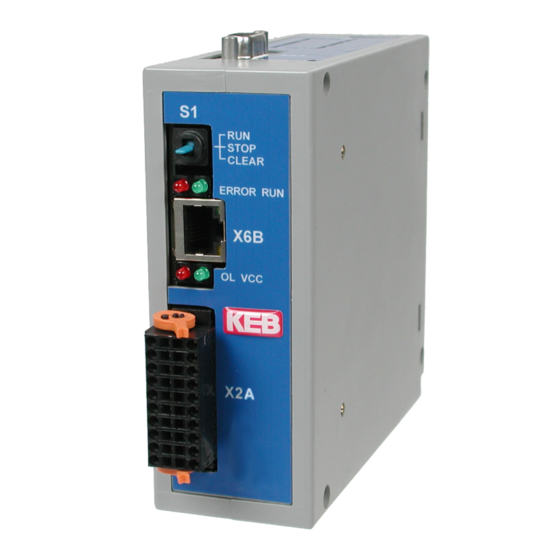
Page 16: The Operating Unit
KEB COMBICONTROL The operating unit View Front Name Function Addition View from the bottom Multi function switch/button Run-LED green ERROR ERROR-LED Overload Voltage supply (US) green Serial interface COMBIVIS Ethernet interface COMBIVIS/ CoDeSys Ethernet interface X1A…D Axis interfaces Serial interface (X6A) The socket X6A is a serial RS232/485 interface. -
Page 17: Ethernet Interface (X6B)
(the node address is set to 0). The file system can be read/ written via port 8002 (only UDP) with KEB ftp-file transfer protocol (writing only with supervisor password). Furthermore access to other ports of this interface can be done via the IEC control program (library SysSocket "). -
Page 18: Multi-Function Switch/Button S1
2.10 File system The file system consists of an internal built-in flash memory (drive C:) and an internal RAM memory (drive B:). Access is possible via the programming system, KEB ftp or directly by the IEC control program (library „SysFile“). - Page 19 KEB COMBICONTROL The following particularities must be observed: • Access is possible only to files in the root directory. • Long file names to 32 characters are possible. For COMPACT II up to 60 cha- racters. • Reading takes place with high speed.
-
Page 20: Fieldbus Interface
KEB COMBICONTROL 2.11 Fieldbus interface Depending on the article number different fieldbus modules are integrated via the fieldbus option cards X6D. Fieldbuses PROFIBUS-DP, CAN and INTERBUS are available at the time. The fieldbus modules operate as slave and are accessed via the library "KebPLC“. Further- more there are finished function blocks for each supported fieldbus, which allow process data allocation and access via the parameterizing channel. -
Page 21: Can Bus Interface
KEB COMBICONTROL 2.11.2 CAN Bus interface Signal Description reserved not connected CAN_L CAN bus signal dominant low CAN_GND not connected reserved not connected CAN_SHLD not connected not connected CAN_H CAN bus signal dominant high reserved not connected CAN_V+ not connected... -
Page 22: Interbus-Interface
KEB COMBICONTROL 2.11.3 INTERBUS-Interface IB_in IB_out BA RD Signal Description Shielding Connect-up at connector housing IB_in Shielding2 Connect-up at connector housing IB_out Data input IB_out Data input IB_in /DI2 Data input inverted IB_out /DO1 Data input inverted IB_in Data output IB_out... -
Page 23: Software
KEB COMBICONTROL Software The units of the series C6 are programmed with the programming system KEB COMBIVIS Studio 6. There are programmable and parameterizing components. Programming system A device description file as well as different libraries are required for the programming of the C6 compact. -
Page 24: Parameter Description
KEB COMBICONTROL Parameter description The following parameters are available in the runtime system and enable the configuration and diagnostics of it. Access to the parameters can also be done via the IEC control program (Library „KebPlc") (OdRead/OdWrite): 3.3.1 Ethernet Parameter et.00... -
Page 25: Real-Time Clock
KEB COMBICONTROL Subnet mask et.11 Address 030Bh The decision whether an IP slave address is outside of the own network is determined with this mask. The mask presents as follows: 0.0.0.0 the standard masks are used depending on network classes A, B or C. In case of doubt the subnet mask to be adjusted can be ask for by the network administrator. -
Page 26: Userdefinition Parameter
KEB COMBICONTROL rc.04 data valid Address 0404h The realtime clock is running for approx. 30 days after switching off the supply. After this it must be adjusted again. If this parameter has the value „false“, the date and/or time is not correct. -
Page 27: Debugging
66019II Address 0007h The baud rate for the KEB DIN 66019II protocol is adjusted with this parameter. If the serial interface X6A is used by the IEC control program, this adjustment is no longer valid. SY.8 response delay 66019II... - Page 28 +39 02 3353531 • fax: +39 02 33500790 net: www.keb.it • mail: kebitalia@keb.it KEB Power Transmission Technology (Shanghai) Co.,Ltd. No. 435 Qianpu Road, Chedun Town, Songjiang District, KEB Japan Ltd. CHN-Shanghai 201611, P.R. China 15–16, 2–Chome, Takanawa Minato-ku fon: +86 21 37746688 • fax: +86 21 37746600 J–Tokyo 108-0074...
Need help?
Do you have a question about the C6-COMPACT and is the answer not in the manual?
Questions and answers