Table of Contents
Advertisement
Quick Links
Advertisement
Table of Contents

Related Manuals for KEB COMBIBOX


Summary of Contents for KEB COMBIBOX
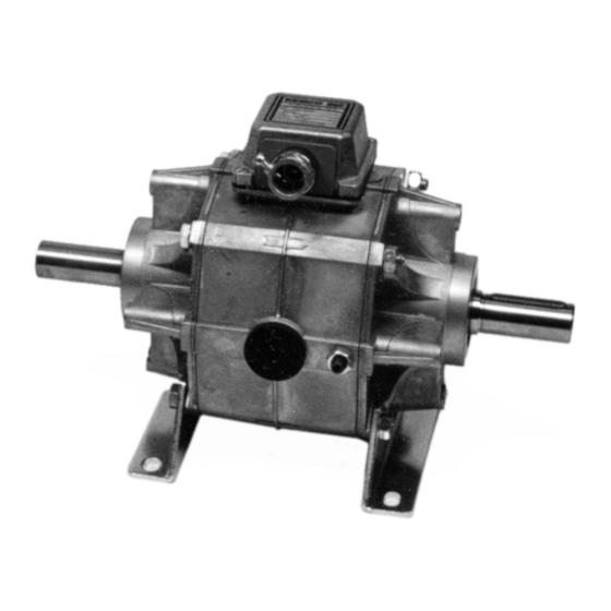
- Page 1 KEB COMBIBOX INSTRUCTION MANUAL 6/2022...
- Page 2 1400. DETERMINING UNIT TYPE In order to properly mount and wire the KEB Combibox, it is necessary to identify the type of the unit. To do this, find the part number of the unit, which is located on top of the terminal box. It should be in the following format: XX.YY.ZZZ...
- Page 3 When AC power is supplied to the Combibox, a rectifier will be used in place of the terminal strip. See Figures 2 and 3 for possible wiring configurations for a type 09 or 10 Combibox. See Figure 4 for the wiring configuration for a type 06 or 16 Combibox.
- Page 4 = 1.5 therefore F = 1.5 x F OPERATION & MAINTENANCE The KEB Combibox is shipped ready for installation with the air gap preadjusted to the nominal value. NEMA, or IEC mounting dimensions on the input and output ends allow for easy assembly to motors and gearboxes.
- Page 5 1. For type 10, engage the brake by supplying the proper DC voltage to the brake magnet. For type 06, no power is required. 2. Remove the access plugs from each side of the Combibox. 3. Loosen the two lock nuts (See Figure 5).
- Page 6 3. Replace the worn clutch rotor with the new rotor Avoid any contamination of the friction lining. The clutch rotor is always on the input side of the Combibox, the arrow on the housing points from the input to the output.
- Page 7 EXPLODED VIEW XX.10.670...
- Page 8 EXPLODED VIEW OF XX.10.370 KEB AMERICA, Inc. 5100 Valley Industrial Blvd S Shakopee, MN 55379 Phone: 1-952-224-1400 • Fax: 1-952-224-1499 www.kebamerica.com info@kebamerica.com...
Need help?
Do you have a question about the COMBIBOX and is the answer not in the manual?
Questions and answers