
Related Manuals for Pfeiffer Vacuum QMA 4X0


Summary of Contents for Pfeiffer Vacuum QMA 4X0
- Page 1 OPERATING INSTRUCTIONS Translation of the Original QMA 4X0 Quadrupole Analyzer for QMG 700 HiQuad ®...
- Page 2 These operating instructions describe all models and variants of your product. Note that your product may not be equipped with all features described in this document. Pfeiffer Vacuum constantly adapts its products to the latest state of the art without prior notice. Please take into account that online operating instructions can deviate from the printed operating instructions supplied with your product.
-
Page 3: Table Of Contents
Foreseeable improper use Responsibilities and warranty Owner requirements Personnel qualification 2.8.1 Ensuring personnel qualification 2.8.2 Personnel qualification for maintenance and repair 2.8.3 Advanced training with Pfeiffer Vacuum Operator requirements Product description Structure Ion sources 3.2.1 Axial ion source 3.2.2 Crossbeam ion source 3.2.3 Grid ion source... - Page 4 7.9.13Adjusting resolution 7.9.14Adapting HF cable polarity Shipping Recycling and disposal General disposal information Dispose of a mass spectrometer system Service solutions by Pfeiffer Vacuum Ordering information 11.1 Ordering parts 11.2 Ordering spare parts Technical data and dimensions 12.1 Technical data...
- Page 5 Table of contents 12.2 Dimensions EC Declaration of Conformity 5/52...
- Page 6 Typical values of the axial ion source Tbl. 4: Typical values of the crossbeam ion source Tbl. 5: Typical values of the grid ion source Tbl. 6: Spare parts for QMA 4x0 Tbl. 7: Technical data Tbl. 8: Dimensions Tbl. 9:...
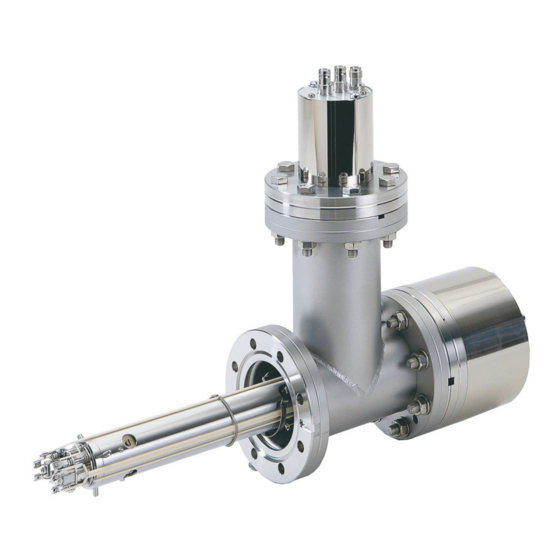
- Page 7 List of figures List of figures Fig. 1: QMA with 90° off-axis SEM Fig. 2: Electrode arrangement and potential curve of the axial ion source Fig. 3: Electrode arrangement and potential curve of the crossbeam ion source Fig. 4: Electrode arrangement and potential curve of the grid ion source Fig.
-
Page 8: About This Manual
QMA 430 You can find the part number on the rating plate of the product. Pfeiffer Vacuum reserves the right to make technical changes without prior notification. The figures in this document are not to scale. Dimensions are in mm unless stated otherwise. -
Page 9: Conventions
This section describes all the stickers on the product along with their meanings. Rating plate The rating plate is located on the side of the unit. D-35614 Asslar Mod. QMA 4x0 PT M0x xxx Made in United States 2022/08 Input 1.3.4 Abbreviations... -
Page 10: Trademark Proof
About this manual Abbreviation Explanation Extreme ultra-high vacuum Yttriated iridium Tbl. 2: Abbreviations used 1.4 Trademark proof ● HiQuad ® is a registered trademark of Pfeiffer Vacuum GmbH. ● QUADERA ® is a registered trademark of Inficon GmbH. 10/52... -
Page 11: Safety
Safety instructions according to product life stages All safety instructions in this document are based on the results of a risk assessment. Pfeiffer Vacuum has taken into account all the relevant life stages of the product. Risks during installation DANGER Danger to life caused by electric voltage on the analyzer During operation, dangerous voltage is present on the electrode system of the QMA analyzer. - Page 12 Safety DANGER Danger to life due to dangerous contact voltage The voltages of the IS 716 and the BIAS, TARGET and EXTR auxiliary voltages are life threatening. ► Observe the technical data of the IS 716. ► Only use professionally made cables. DANGER Danger to life from electric shock The voltages under the connector plates are life threatening.
-
Page 13: Safety Precautions
Safety Risks during disposal WARNING Health hazard through poisoning from toxic contaminated components or devices Toxic process media result in contamination of devices or parts of them. During maintenance work, there is a risk to health from contact with these poisonous substances. Illegal disposal of toxic sub- stances causes environmental damage. -
Page 14: Responsibilities And Warranty
● Use with replacement or accessory parts that are not suitable or not approved 2.6 Responsibilities and warranty Pfeiffer Vacuum shall assume no responsibilities and warranty if the operating company or a third party: ● disregards this document ● does not use the product for its intended purpose ●... -
Page 15: Personnel Qualification For Maintenance And Repair
─ Customer with Pfeiffer Vacuum service training ─ Pfeiffer Vacuum service technician 2.8.3 Advanced training with Pfeiffer Vacuum For optimal and trouble-free use of this product, Pfeiffer Vacuum offers a comprehensive range of courses and technical trainings. For more information, please contact Pfeiffer Vacuum technical training. -
Page 16: Product Description
Product description 3 Product description 3.1 Structure A quadrupole analyzer consists of: ● Ion source ● Mass filter with quadrupole rods ● Ion detector (SEM and deflection unit with Faraday, or only Faraday) ● Housing with flanges Through high mechanical accuracy and the optimization of the ion-optic unit of ion source and rod sys- tem, the analyzers achieve a high resolution, high transmission and low mass discrimination. -
Page 17: Axial Ion Source
Product description decisive factor for the quality of the entire analysis. Errors in this part of the process can largely not be corrected in the later steps. Choosing the correct ion source is crucial. Closed (gas-tight) ion sources allow gas analysis with minimal contribution of the residual vacuum. They exhibit practically no de-mix- ing, have a high signal-to-ground ratio, low gas consumption and a low time constant. -
Page 18: Crossbeam Ion Source
Product description Emission 1 mA Ion Reference 90 V Cathode 70 eV Focus 20 V Field Axis 10 V Inner Deflection 300 V Wehnelt 30 V (max. 40) Protection Current 4.2 A 3.5 A Tbl. 3: Typical values of the axial ion source 3.2.2 Crossbeam ion source The open design of the crossbeam ion source allows quick reaction to changes in the gas composition. -
Page 19: Grid Ion Source
Product description Degas Degassing the crossbeam ion source is only recommended in exceptional cases. ● Pressure: ≤ 10 ● Emission: ≤ 10 mA (at 550 V) ● Time: ≤ 5 minutes 1 2 3 100 V -100 V Fig. 3: Electrode arrangement and potential curve of the crossbeam ion source 1 Wehnelt Base plate... -
Page 20: Fig. 4: Electrode Arrangement And Potential Curve Of The Grid Ion Source
Product description Application examples ● Residual gas analysis in UHV ● Desorption measurements Function The two electrons which are emitted by the ring cathode are accelerated toward the grid and mainly pass through the grid. The ions formed inside the grid are drawn to the mass filter by the grounded en- trance orifice. -
Page 21: Mass Filter
Product description Inner Deflection 200 V Protection Current 4.2 A 3.5 A Tbl. 5: Typical values of the grid ion source 3.3 Mass filter The correct material selection and highly precise manufacturing methods ensure a high degree of line- arity and reproducibility. 3.3.1 QMA 430 The 8 mm rod system made of stainless steel can be used up to mass number 300. -
Page 22: Detecting Negative Ions
Product description 3.4.2 Detecting negative ions CP 400 0...-3.5kV +3.1kV HV 702 Fig. 6: Detecting negative ions Procedure ► With HV 702, apply +3.1 kV to the 1st dynode (HV-) for detection of negative ions (-3.1 kV for pos- itive ions). –... -
Page 23: Electron Collimation Magnet
– Not all materials are available for all ion source types. 3.5.2 Electron collimation magnet Pfeiffer Vacuum recommends equipping the crossbeam ion source with a magnet unit for applications in high mass ranges, for molecular beam detection, and in the QMA 410 for separating He and D2. The magnet increases the real path length of the electrons and thus the ion yield. -
Page 24: Identifying The Product
You will need all the data from the rating plate to safely identify the product when communicating with Pfeiffer Vacuum. ► To ensure clear identification of the product when communicating with Pfeiffer Vacuum, always keep all of the information on the rating plate to hand. -
Page 25: Transport And Storage
Transport and storage 4 Transport and storage 4.1 Transporting the product NOTICE Damage caused by incorrect transport Transport in unsuitable packaging or failure to install all transport locks can result in damage to the product. ► Comply with the instructions for safe transport. Packing We recommend keeping the transport packaging and original protective cover. -
Page 26: Installation
Installation 5 Installation 5.1 Preparing analyzer for installation DANGER Danger to life caused by electric voltage on the analyzer During operation, dangerous voltage is present on the electrode system of the QMA analyzer. Com- ponents in the vacuum system are dangerous to touch under certain conditions. There is danger to life due to electric voltage. -
Page 27: Preparing Gas Inlet System
Installation 5.1.2 Preparing gas inlet system Fig. 9: Correct alignment on the flange of the QMA with C/B ion source Procedure ► Prepare the gas inlet system as necessary to enable easy connection to the ion source afterward. ► Mark the correct alignment (arrow direction) on the flange of the QMA and of the system, if the crossbeam ion source has to be aligned to the gas supply. -
Page 28: Using Assembling Trestle
Installation 5.1.4 Using assembling trestle Fig. 11: Analyzer on the assembling trestle 1 Analyzer Assembling trestle 2 Support Procedure 1. Clamp the assembling trestle onto a stable table. 2. Place the analyzer with the support on the assembling trestle. 5.1.5 Removing transportation protection NOTICE Impairment from contamination and damage Touching the devices or components with bare hands increases the desorption rate and leads to in-... -
Page 29: Removing Protective Pipe
Installation Fig. 12: Removing transportation protection 1 Transport protection Analyzer housing 2 Mass filter Procedure 1. Carefully remove the transportation protection and store it for future use. 2. Check the inside for damage and wiring short-circuits. 5.1.6 Removing protective pipe Prerequisites ●... -
Page 30: Installing Electron Collimation Magnets
Installation 5.1.7 Installing electron collimation magnets NOTICE Impairment from contamination and damage Touching the devices or components with bare hands increases the desorption rate and leads to in- correct measurements. Dirt (e.g. dust, fingerprints, etc.) and damage impair the function. ► During assembly and maintenance work on high or ultra high vacuum systems, always wear clean, lint-free and powder-free laboratory gloves. -
Page 31: Installing Analyzer
► During installation, hold the vertical seal stationary with a knife blade. Perform installation work as a 2-person team Depending on the installation position, the work can be difficult. Pfeiffer Vacuum recommends letting a second person assist, to prevent damage. Prerequisite ● Installation area free of obstacles Required tools ●... -
Page 32: Connecting The Gas Inlet System
Installation 5.3 Connecting the gas inlet system CAUTION Health risks and environmental damage due to the process gases used Gases used (process gases) represent a health risk and damage to the environment. ► Check the leak tightness of the connections before introducing the process gas. ►... -
Page 33: Mounting Ion Counter Pre-Amplifier Cp 400
Installation Fig. 17: SEM connector plate 1 Screw (3×) 2 Hexagon socket screw (3×, SW 1.5 mm) General approach ► To remove the SEM connector plate, remove the EP 422. ► Remove the SEM connector plate or – if you have an analyzer without SEM connector plate – re- move the cover prior to installing the CP 400. -
Page 34: Commissioning
5. If you do not have the test log any more, activate the default setting for your ion source and opti- mize it. – In complete systems, Pfeiffer Vacuum factory-calibrated the high-frequency generator specifi- cally for the analyzer. Calibrating high-frequency generator In complete systems, Pfeiffer Vacuum factory-calibrated the high-frequency generator specifically for the analyzer. -
Page 35: Operation
Setting the crossbeam ion source with magnet For analyses at different pressures, Pfeiffer Vacuum recommends removing the magnetic unit or reduc- ing the emission to 0.1 mA. At low emission levels (up to 0.1 mA), the procedure described in the "Set- ting without magnet"... -
Page 36: Adjusting Grid Ion Source
Operation 7.1.3 Adjusting grid ion source Procedure 1. Start with the last values that provided good results, the values from the test log or, if nothing bet- ter is available, with typical values. 2. Adjust the "IonRef" to maximum peak height, however the value always has to be higher than the "Cathode"... -
Page 37: Baking Out Analyzer
► Let the flange cool to <50 °C before you mount the EP 422, CP 400 and HF generator again. 7.5 Assessing sensitivity Pfeiffer Vacuum determines the sensitivity with and without SEM in the factory. The test log included in the delivery of the product contains the values that were determined. The sensitivity is specified in A/hPa for a reference gas. -
Page 38: Surface Ions
Operation 7.7 Surface ions Under the electron bombardment in the ion source, adsorbed contaminations are desorbed as so-called EID ions, which then appear in the spectrum, e.g. with masses 16 (O+), 19 (F+), 23 (Na+), 35/37 (Cl+) and 39/41 (K+). EID ions mainly become apparent during UHV measurements. They can be reduced by degassing (degas or temporary operation with high emission). -
Page 39: Selecting Recommended Operating Modes
Operation 7.9.1 Selecting recommended operating modes Fig. 19: Default parameters of the Ion Source Tuning program of the Quadera software Fig. 20: Optimized ion source parameters for spectrum with nitrogen and oxygen, using a CB-IQ as an example Using "Ion Source Tuning" The "Mass Mode: SCAN-N"... -
Page 40: Optimization With Test Gas
Operation 7.9.2 Optimization with test gas Procedure 1. Let a suitable gas with a pressure of 5 × 10 hPa flow in (for special ion sources). – To optimize for higher masses, corresponding components have to be included, else air is ad- equate. -
Page 41: Configuring "V2 Cathode" Ion Source Parameter
Operation 7.9.6 Configuring "V2 Cathode" ion source parameter NOTICE Overloading of the filament At a reduced ionization energy setting ("Cathode" e.g. 40 eV), the filament temperature required for the emission increases. The filament burns out. ► In this case, reduces the emission to 0.1 mA, for example. ►... -
Page 42: Configuring "V5 Extraction" Ion Source Parameter
Operation proved by reducing the "Field Axis" value, there may be contamination or mechanical problems (e.g. ion source not correctly centered, or assembled in a tilted position). The "Surface ions" chapter shows how normal and so-called EID ions can be differentiated with the aid of the "Field Axis" parameter. 7.9.9 Configuring "V5 Extraction"... -
Page 43: Shipping
► Comply with the instructions for safe distribution. Decontamination subject to charge Pfeiffer Vacuum decontaminates products not clearly declared "Free of contamination" at your expense. Ship product safely ► Do not ship microbiological, explosive or radioactively contaminated products. -
Page 44: Recycling And Disposal
– Fluoroelastomers (FKM) – Potentially contaminated components that come into contact with media 9.2 Dispose of a mass spectrometer system Pfeiffer Vacuum mass spectrometer systems contain materials that you must recycle. 1. Dismantle the housing parts. 2. Dismantle all individual components. -
Page 45: Service Solutions By Pfeiffer Vacuum
We are always focused on perfecting our core competence – servicing of vacuum components. Once you have purchased a product from Pfeiffer Vacuum, our service is far from over. This is often exactly where service begins. Obviously, in proven Pfeiffer Vacuum quality. - Page 46 Service solutions by Pfeiffer Vacuum 5. Prepare the product for transport in accordance with the provisions in the contamination declaration. a) Neutralize the product with nitrogen or dry air. b) Seal all openings with blind flanges, so that they are airtight.
-
Page 47: Ordering Information
BN845088 -T Filament unit with 2 iridium filaments, Y -coated, for cross beam ion source, also BN845282 -T gas tight Filament unit with 2 tungsten filaments, for grid ion source BN845095 -T Tbl. 6: Spare parts for QMA 4x0 47/52... -
Page 48: Technical Data And Dimensions
Technical data and dimensions 12 Technical data and dimensions 12.1 Technical data Parameter Value Overpressure Permissible overpressure ≤ 2000 hPa (absolute) Vacuum Operating pressure (Faraday) ≤1 × 10 hPa in the ion source Operating pressure (SEM) ≤1 × 10 hPa in the ion source 9) 10) Sensitivity Smallest detectable partial pressure (Faraday) -
Page 49: Fig. 23: Dimensions
Technical data and dimensions Parameter Value Crossbeam (gas tight), with an axial connector Bore in glass ceramic for tube with outer diameter 3 mm Bakeout temperature Without cables and connector plates ≤400°C With electron collimation magnet ≤300°C With cables and connector plates ≤180°C With pre-amplifier or electrometer ≤50°C... - Page 50 Technical data and dimensions Dimension [mm] 90° off-axis SEM Faraday QMA 400 QMA 430 QMA 410 QMA 400 QMA 410 267.5 269.2 DN 63 CF DN 63 CF DN 100 CF DN 63 CF DN 100 CF DN 63 CF DN 63 CF DN 63 CF Ø...
- Page 51 EC Declaration of Conformity Declaration for product(s) of the type: Analyzer QMA 4x0 We hereby declare that the listed product satisfies all relevant provisions of the following European Directives. Basse tension 2014/35/CE Electromagnetic compatibility 2014/30/EU Restriction of the use of certain hazardous substances, 2011/65/EU (Article 2, number...
Need help?
Do you have a question about the QMA 4X0 and is the answer not in the manual?
Questions and answers