Table of Contents
Advertisement
Advertisement
Table of Contents

Related Manuals for Pfeiffer Vacuum QMA 125


Summary of Contents for Pfeiffer Vacuum QMA 125
- Page 1 Operating Instructions Quadrupole Analyzer QMA 125 BG 805 988 BE (2004-04)
-
Page 2: Product Identification
We reserve the right to make technical changes without prior notice. Intended Use The QMA 125 analyzers are designed for gas analysis in the high vacuum and ultra high vacuum range. They are parts of the Pfeiffer Vacuum quadrupole mass spec- trometry system and may be used only in connection with system components defined for this purpose. -
Page 3: Table Of Contents
Contents Product Identification Validity Intended Use 1 Safety 1.1 Symbols Used 1.2 Personnel Qualifications 1.3 General Safety Instructions 1.4 Liability and Warranty 1.5 Training 2 Description 2.1 System Structure 2.2 Ion Sources 2.2.1 Axial Beam Ion Source 2.2.2 Gas-Tight Ion Source 2.2.3 UHV Grid Ion Source 2.2.4 Crossbeam Ion Source 2.2.5 Cathode Materials... - Page 4 7.1.2 Grid Ion Source 7.1.3 Crossbeam Ion Source 7.2 Replacing the SEM 217 / C-SEM 7.2.1 SEM 217 7.2.2 C-SEM 7.3 Removing the Connector Housing 7.3.1 All Connector Housings Except the Housing for the SEM 217 7.3.2 Connector Housing for the 90° off-axis SEM 217 7.3.3 Connector Housing SEM 7.4 Checks to be Made After Maintenance Work on the Analyzer 8 Accessories...
-
Page 5: Safety
• In case of toxic or explosive gases being measured by the QMA 125, exhaust gases have to be treated according to the regulations. Safety measures •... -
Page 6: Liability And Warranty
1.4 Liability and Warranty Pfeiffer Vacuum assumes no liability and the warranty becomes null and void if the operator or third parties • disregard the information in this document • use the product in a non-conforming manner • make any kind of changes (modifications, alterations etc.) to the product •... -
Page 7: Description
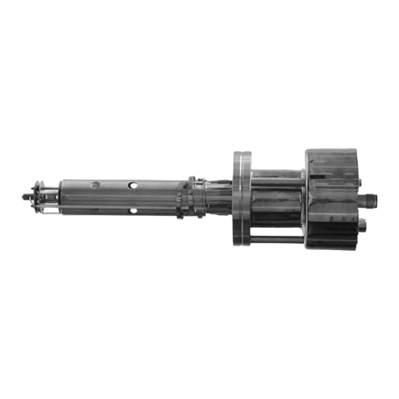
A quadrupole analyzer consists of: • Ion source • Rod system (mass filter) • Ion detector (cup) • Connector housing • Ion deflection unit Faraday collector QMA 125 EP 422 (90°-Ion- Ion source Mass filter deflection unit) SEM or C-SEM High- Ion source RF-generator... -
Page 8: Axial Beam Ion Source
All the ion sources suited for use in the QMA 125 analyzer feature the following: • The voltage between the formation chamber and the mass analyzer entry ap- erture (ground) is higher than that between the formation chamber and the fila- ment. -
Page 9: Gas-Tight Ion Source
2.2.2 Gas-Tight Ion Source The design of the gas-tight ion source corresponds closely to that of the axial beam ion source. In the gas-tight source the grid is placed over a smaller aperture to allow entry of the electrons. The gas to be analyzed is fed directly into the ion source formation chamber (4) via a metal capillary at ground potential (6) and an insulating intermediate piece (5). -
Page 10: Cathode Materials
The electrons emitted by one of the two filaments (1) are accelerated into the formation chamber (2) perpenticular to the system axis. The emitted electrons are collimated by the Wehnelt electrode (3) mounted on the filament block and connected to the filament at one end. The extraction aperture (4) generates a weak electrical field in the formation chamber which is used to extract the... -
Page 11: Ion Detectors
Field axis –(U + V cos ω t) + ( U + V cos ω t) 2.4 Ion Detectors General The ion detector can be a simple Faraday cup or, for sensitive measurements, a SEM (Secondary Electron Multiplier) or a C-SEM (Continuous Dynode Secondary Electron Multiplier). -
Page 12: Sem 217 Secondary Electron Multiplier With Discrete Dynodes
Principle of Operation If an ion, electron, photon or fast neutral particle hits the entry channel of the C-SEM, electrons are released from its surface. These are accelerated by the electrical field Mass filter and, because of the bend in the tube, hit the surface again further on where they release secondary electrons. -
Page 13: Ion Deflection Unit (For Sem 90° Operation)
The detection capability of the SEM is a Gain function of the number of electrons re- leased from the conversion dynode per impinging ion. The total gain, in contrast, is determined chiefly by the secondary elec- tron rate of the individual dynodes. Both these rates are to a large extent a function of the dynode surface structure. -
Page 14: Technical Data
3 Technical Data ≤2 bar (absolute) Admissible overpressure (absolute) Overpressure Operating pressure Vacuum − 4 ≤1×10 with Faraday mbar − 5 ≤1×10 with SEM mbar Lowest detectable partial pressure Sensitivity − 11 without SEM 3×10 mbar − 14 C-SEM 5×10 mbar with 90°... - Page 15 1×10 A/mbar 1×10 A/mbar Number of stages Dynode material Cu/Be Voltage divider MΩ/ stage Dimensions QMA 125 with SEM 90° off - axis QMA 125 with C-SEM QMA 125 DN 63 CF-F ø74 ø74 ø74 *Axial beam ion source 30.5 mm...
-
Page 16: Installation
4.1 Preparation DANGER Caution: hazardous electrical voltages Hazardous voltages up to 600 V are applied to the QMA 125. Make sure the QMA, the vacuum chamber, and the whole system are always correctly connected to ground. If accidental contact to the QMA is possible when the vacuum system... -
Page 17: Installing The Analyzer
Each QMA 125 analyzer is supplied with a bracket which allows the QME 125 mass filter electronics to be mounted to the QMA connection flange (→... - Page 18 Analyzer With 90° SEM This analyzer has a DN 63 CF flange (flange 2). It has to be operated in the T-shaped housing, unless there is no SEM required for the application. It is supplied under vacuum in a sealed protection tube, which should not be re- moved until shortly before the analyzer is installed.
-
Page 19: Ep 422
4.5 Electrical Connections The details of the electrical connections between the analyzer QMA 125 and the QME 125 depend on the analyzer being used and the application for which it is intended. The following table gives all feasible configurations. - Page 20 Identifying the Cables Cable Length [m] Ordering number. Connection QMS - QME BG448167-T Extension QMS - QME BG448197-T Extension QMS - QME BG448170-T RF/ion source (QMA) 0.17 mounted on QME 125 Electrometer supply mounted on EP 422 High voltage BG448083-T High voltage BG548996-T Protection ground...
- Page 21 Connecting an Oscilloscope C-SEM-operation SEM-operation Scan in Scan in Progress Progress HV– EP 422 ext. Trigger ext. Trigger EP 422 HV– Scope Scope HV– Ground connection at the clamping ring of the QME125 (→ [1]). BG 805 988 BE (2004-04) QMA125.oi...
-
Page 22: Start Up
5 Start Up 5.1 First Time operation The analyzer can only be operated as part of an entire mass spectrometer system consisting of: • QMS 422 control unit • QME 125 quadrupole electronics • EP 422 electrometer amplifier Before switching the equipment on check that all components are correctly installed and wired. -
Page 23: Operation With The C-Sem Or Sem
A vacuum system that has not been recently conditioned usually contains a certain amount of water vapor and air. In case of doubt, we recommend admitting some air − 6 to a pressure of, for example, 10 mbar. It may be necessary to readjust the resolution and mass scale (→ [1]). -
Page 24: Axial Beam Ion Source (Also Applies To Gas-Tight Version)
5.2.1 Axial Beam Ion Source (Also Applies to Gas-Tight Version) Settings QME 125 → <ion source> 100 eV …1 mA <emission> 5 … 7 V <field axis> I [A] E-09 E-10 E-11 E-12 − 5 Spectrum of a Viton-sealed vacuum chamber containing approx. 1×10 mbar re- sidual gas (axial beam ion source, Faraday cup). -
Page 25: Grid Ion Source
Ion current Typical ion current curve shown as a optimum operation function of the field axis voltage. We recommend also taking this curve your- self (maximum of the integral spectrum). Axial The optimum value is at ≈70% of the full beam scale deflection. -
Page 26: C-Sem
Holding to the following rules will assure a long lifetime for the C-SEM: 5.2.4 C-SEM • The C-SEM surfaces can be exposed repeatedly to normal, ambient air without suffering damage. However, they must be kept free of dust. Always wear suit- able gloves and use carefully cleaned tools when assembling and otherwise handling the C-SEM. -
Page 27: Degas Mode
5.2.6 DEGAS Mode Using the DEGAS function for degassing is only recommended for grid ion sources. − 8 A total pressure of <10 is required for operation in this mode. It is a good idea to bakeout the analyzer for several hours before degassing. 5.3 Operating - and Bakeout Admissible temperatures →... -
Page 28: Maintenance
When operated under clean vacuum conditions the QMA 125 has a very long life- time. Only the filament, and in particular the rhenium filament, have limited life- times. -
Page 29: Removing And Cleaning The Ion Sources
6.2 Removing and Cleaning DANGER the Ion Sources Caution: contaminated parts Contaminated parts can be detrimental to health and environment. Before beginning to work, find out whether any parts are contaminated. Adhere to the relevant regulations and take the necessary precautions when handling contaminated parts. -
Page 30: Mounting Tool
Abrasive cleaning can deform thin metal sheeting. Fine mesh grids cannot be cleaned mechanically. These parts must be replaced when contaminated. After mechanical cleaning, wash the parts in a solvent such as acetone etc. and rinse with alcohol. We also recommend ultrasonic cleaning here and subsequent drying in hot air. -
Page 31: Axial Beam Ion Source (Also Applies To Gas-Tight Version)
6.2.2 Axial Beam Ion Source • Remove the analyzer from the (Also Applies to vacuum system and put it on the mounting tool. Gas-Tight Version) From this point on wear clean gloves when handling the parts. • Remove the filament (→ 39). -
Page 32: Grid Ion Source
6.2.3 Grid Ion Source • Remove the analyzer from the vacuum system and put it on the mounting tool ( → 30). From this point on wear clean gloves when handling the parts. • Remove the filament ( → 39). •... -
Page 33: Crossbeam Ion Source
6.2.4 Crossbeam Ion Source • Remove the analyzer from the vacuum system and put it on the mounting tool ( → 30). From this point on wear clean gloves when handling the parts. • Remove the filament ( → 40). •... -
Page 34: Analyzer With C-Sem
6.3.2 Analyzer With C-SEM • Remove analyzer. • Place the analyzer on an mounting tool with the connection head facing downwards ( → 30). • Disconnect flange 1, and remove the DN 63/40 CF reducing piece if it is being used. From this point on wear clean gloves when handling the parts. -
Page 35: Analyzer With 90° Sem
6.3.3 Analyzer With 90° SEM • Remove analyzer. • Place the analyzer on the mounting tool with connector housing 1 facing down- wards ( → 30). Do not disconnect flange 1 yet. • Unscrew bolts on flange 2 and remove the flange together with the SEM 217 (e). -
Page 36: Taking Apart The Mass Filter
Rinsing in a solvent, even with ultrasonic enhancement, is often not enough to properly clean it. In these cases we recommend returning the product to your local Pfeiffer Vacuum service center for service. BG 805 988 BE (2004-04) QMA125.oi... -
Page 37: Cleaning The Rod System
6.3.5 Cleaning the Rod System Always wear lint free gloves when handling the rod system. Usually only the inner side of the rods need to be cleaned i.e. the surfaces facing the system axis. The rod system is cleaned in a dry process using an abrasive cleaner such as slurry chalk or very fine aluminum oxide powder. -
Page 38: Repair
We recommend returning the product to your local Pfeiffer Vacuum service center for repair. Pfeiffer Vacuum assumes no liability and the warranty becomes null and void if any repair work not described in the documentation is carried out by the end-user or third parties. -
Page 39: Replacing The Filament
7.1 Replacing the Filament Check for continuity and insulation each time after each filament re- placement and before the analyzer is used again. 7.1.1 Axial Beam Ion Source • Deinstall the analyzer ( → 31). (Also Applies to Gas- • Loosen screws (a) and remove Tight Version) filament (b). - Page 40 7.1.3 Crossbeam Ion Source • Deinstall the analyzer ( → 31). • Hold the U-shaped clamping holder in place with flat-nosed pliers, and loosen the screws (a) in the filament connector. Pull them out upwards to- gether with the U-shaped clamping holder.
- Page 41 7.2 Replacing the SEM 217 / C-SEM 7.2.1 SEM 217 • Deinstall the analyzer. • Place the analyzer on the mounting tool with connector housing 1 facing down- wards. ( → 30). Do not disconnect flange 1. • Disconnect flange 2, remove the complete SEM (e) and place it on a suitable surface.
- Page 42 C-SEM. Proceed in Except the Housing for the same manner for other QMAs. the SEM 217 • Disconnect the electrical connections for the QMA 125. • Remove the two screws (a). • Carefully pull off the cylindrical out- side tube.
- Page 43 7.3.2 Connector Housing for • Disconnect electrical connections the 90° off-axis SEM 217 and EP422. • Loosen screws (a) and pull off the analyzer cover (b). • Loosen the hex socket head screw (c) for the shielding sleeve (h), slide the sleeve up to the mechanical stop in the open position, and retighten screws.
- Page 44 8 Accessories Ordering number Ion source: Axial beam ion source BG528302-T Gas-tight ion source BK378749-T Grid ion source BG528370-T Crossbeam ion source BG444000/T Conversion wiring: Axial to grid ion source BG528366-T Grid to axial ion source BG528365-T 9 Spare Parts When ordering spare parts, always indicate: •...
- Page 45 13 Anhang Literatur [1] www.pfeiffer-vacuum.de Operating Instructions Quadrupole Electronics QME 125 BG 805 987 BE Pfeiffer Vacuum GmbH, D-35614 Asslar [2] www.pfeiffer-vacuum.de Operating Instructions Quadrupole mass spectrometer QMG 422 BG 805 981 BE Pfeiffer Vacuum GmbH, D-35614 Asslar BG 805 988 BE (2004-04) QMA125.oi...
- Page 46 Electrical Connections and Pin Assignment BG 805 988 BE (2004-04) QMA125.oi...
- Page 47 BG 805 988 BE (2004-04) QMA125.oi...
- Page 48 BG 805 988 BE (2004-04) QMA125.oi...
- Page 49 BG 805 988 BE (2004-04) QMA125.oi...
- Page 50 Declaration of Contamination The service, repair, and/or disposal of vacuum equipment and components will only be carried out if a correctly completed declaration has been submitted. Non-completion will result in delay. This declaration may only be completed (in block letters) and signed by authorized and qualified staff. Description of product Reason for return Type...
- Page 51 Notes BG 805 988 BE (2004-04) QMA125.oi...
- Page 52 Berliner Strasse 43 D–35614 Asslar Deutschland Tel +49 (0) 6441 802-0 Fax +49 (0) 6441 802-202 info@pfeiffer-vacuum.de Original: German BG 805 988 BD (2004-04) www.pfeiffer-vacuum.de bg805988be...
Need help?
Do you have a question about the QMA 125 and is the answer not in the manual?
Questions and answers