Table of Contents
Advertisement
Quick Links
Advertisement
Table of Contents
Troubleshooting

Related Manuals for Mitsubishi Electric NZ2GF-CCB


Summary of Contents for Mitsubishi Electric NZ2GF-CCB
- Page 1 CC-Link IE Field Network-CC-Link Bridge Module User's Manual -NZ2GF-CCB...
-
Page 3: Safety Precautions
SAFETY PRECAUTIONS (Read these precautions before using this product.) Before using this product, please read this manual and the relevant manuals carefully and pay full attention to safety to handle the product correctly. The precautions given in this manual are concerned with this product only. For the safety precautions of the programmable controller system, refer to the user's manual for the CPU module used. - Page 4 [Security Precautions] WARNING ● To maintain the security (confidentiality, integrity, and availability) of the programmable controller and the system against unauthorized access, denial-of-service (DoS) attacks, computer viruses, and other cyberattacks from external devices via the network, take appropriate measures such as firewalls, virtual private networks (VPNs), and antivirus solutions.
- Page 5 [Wiring Precautions] CAUTION ● Prevent foreign matter such as dust or wire chips from entering the module. Such foreign matter can cause a fire, failure, or malfunction. ● Place the cables in a duct or clamp them. If not, dangling cable may swing or inadvertently be pulled, resulting in damage to the module or cables or malfunction due to poor contact.
-
Page 6: Conditions Of Use For The Product
Notwithstanding the above restrictions, Mitsubishi Electric may in its sole discretion, authorize use of the PRODUCT in one or more of the Prohibited Applications, provided that the usage of the PRODUCT is limited only for the specific applications agreed to by Mitsubishi Electric and provided further that no special quality assurance or fail-safe, redundant or other safety features which exceed the general specifications of the PRODUCTs are required. -
Page 7: Introduction
INTRODUCTION Thank you for purchasing the CC-Link IE Field NetworkCC-Link bridge module (hereafter abbreviated as bridge module). This manual describes the procedures, system configuration, parameter settings, functions, and troubleshooting of a bridge module. Before using this product, please read this manual and the relevant manuals carefully and develop familiarity with the functions and performance of the bridge module to handle the product correctly. -
Page 8: Relevant Manuals
RELEVANT MANUALS (1) CC-Link IE Field Network (relevant) manuals When using the CC-Link IE Field Network for the first time, refer to the CC-Link IE Field Network Master/Local Module User's Manual first. The following shows the structure of the CC-Link IE Field Network manuals. Manual name Description <manual number (model code)>... - Page 9 Memo...
-
Page 10: Table Of Contents
CONTENTS CONTENTS SAFETY PRECAUTIONS ............. 1 CONDITIONS OF USE FOR THE PRODUCT . - Page 11 6.4.3 Wiring of a CC-Link dedicated cable ..........49 CHAPTER 7 VARIOUS SETTINGS Parameter Settings for CC-Link IE Field Network .
- Page 12 Appendix 4 Added and Enhanced Functions ......... . 132 Appendix 5 EMC and Low Voltage Directives .
-
Page 13: Manual Page Organization
MANUAL PAGE ORGANIZATION In this manual, pages are organized and the symbols are used as shown below. The following illustration is for explanation purpose only, and should not be referred to as an actual documentation. "" is used for window names and items. -
Page 14: Terms
Unless otherwise specified, this manual uses the following terms. Term Description The abbreviation for the NZ2GF-CCB CC-Link IE Field Network CC-Link bridge module Bridge module Buffer memory A memory in a bridge module, where data (such as setting values and monitoring values) are stored... - Page 15 Term Description A generic term for stations other than a master station: local station, remote I/O station, remote device station, and Slave station intelligent device station A function of communication with another station, which is used when requested by a dedicated instruction or the Transient transmission engineering tool...
-
Page 16: Packing List
PACKING LIST The following items are included in the package of this product. Before use, check that all the items are included. NZ2GF-CCB Bridge module Safety Guidelines A set of terminating resistors for CC-Link Terminating resistor 110 1/2W Notes about... -
Page 17: Chapter 1 Bridge Module
CHAPTER 1 BRIDGE MODULE CHAPTER 1 BRIDGE MODULE This chapter describes the application and features of the bridge module. Application A bridge module is a module to connect a CC-Link remote station to CC-Link IE Field Network. A bridge module allows a CC-Link Ver.1-compatible CC-Link remote station to connect to CC-Link IE Field Network. For the functions of CC-Link IE Field Network, refer to the following. - Page 18 (3) Independent cyclic transmission Cyclic transmission of CC-Link is independent from CC-Link IE Field Network. In addition, the cyclic transmission of CC-Link IE Field Network is not affected even when the communication status of CC-Link changes. CC-Link Master station Bridge module remote station CPU module Master/local module...
-
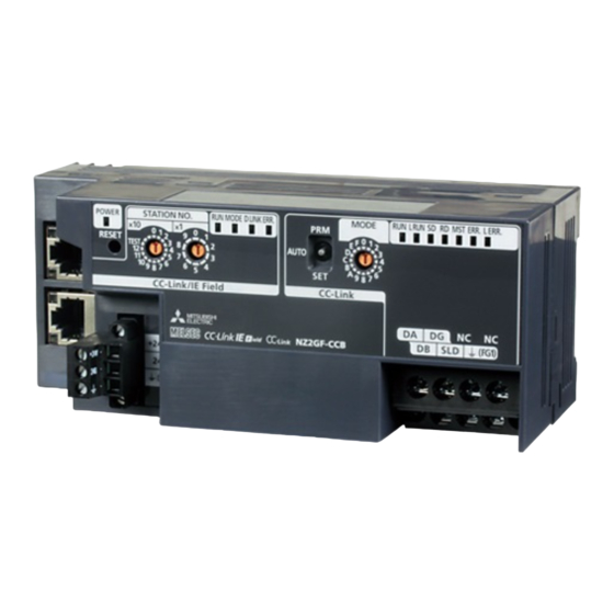
Page 19: Chapter 2 Part Names
CHAPTER 2 PART NAMES CHAPTER 2 PART NAMES This chapter describes the part names of a bridge module. Name Description Indicates the power supply status of the bridge module. POWER LED (green) ON: Power supply on OFF: Power supply off ... - Page 20 Name Description Indicates the status of CC-Link. Indicates the operating status of the bridge module. RUN LED (green) ON: Operating normally OFF: A hardware failure or watchdog timer error has occurred. Indicates the data link status. L RUN LED (green) ON: Performing data link OFF: Not performing data link Indicates whether the module is sending data.
- Page 21 CHAPTER 2 PART NAMES Name Description Sets the transmission speed and mode of CC-Link. (Default: 0) Set the same value of the transmission speed for all stations. Transmission speed Mode Switch number setting Transmission speed 156kbps Transmission speed 625kbps Transmission speed Online 2.5Mbps Transmission speed...
-
Page 22: Chapter 3 Specifications
CHAPTER 3 SPECIFICATIONS This chapter describes the specifications of the bridge module. General Specifications The following table lists the general specifications of the bridge module. Item Specifications Operating ambient 0 to 55 temperature Storage ambient temperature -25 to 75 Operating ambient humidity 5 to 95%RH, non-condensing Storage ambient humidity Constant... -
Page 23: Performance Specifications
CHAPTER 3 SPECIFICATIONS Performance Specifications The following table lists the performance specifications of the bridge module. (1) Hardware specifications Item Specifications Protection code IP2X CC-Link IE Field RJ45 connector External Network connection Module power supply Terminal block for module power supply and FG system CC-Link Terminal block for CC-Link (two-piece, M3 screw) - Page 24 (3) CC-Link specifications Item Specifications Compatible CC-Link version Ver.1.10 Up to 64 modules (However, the following conditions must be satisfied.) a: Number of modules occupying 1 station b: Number of modules occupying 2 {(1 a) + (2 b) + (3 c) + (4 Conditi stations ...
-
Page 25: Function List
CHAPTER 3 SPECIFICATIONS Function List The following table lists the functions of the bridge module. (1) Functions of CC-Link IE Field Network Function Description Reference Checks for an network error from the engineering tool CC-Link IE Field Network connected to the master station using the CC-Link IE Page 78, Section 9.3 diagnostic function Field Network diagnostic function. -
Page 26: Flow Of Data During Communications
Flow of Data during Communications The bridge module communicates with a master station and a CC-Link remote station using link devices (RX/RY/RWr/RWw). This section describes the flow of the link devices between the bridge module and the master station or a CC-Link remote station. - Page 27 CHAPTER 3 SPECIFICATIONS (1) Remote input (RX) The data in the RX of the CC-Link remote station is stored in the RX of the bridge module by the link scan of CC-Link. The bridge module transfers the data from CC-Link to CC-Link IE Field Network. The data in the RX of the bridge module is stored in the RX of the master station by the link scan of CC-Link IE Field Network.
-
Page 28: List Of Remote I/O Signals
List of Remote I/O Signals The following table lists the remote I/O signal (RX/RY) assignment of the bridge module. • Assignment example ( Page 29, Section 3.7) (1) Remote input (RX) Bridge module to master station (RX) Address Description RX n+0 RX0 of CC-Link RX0 of the station number 1 RX n+1... -
Page 29: List Of Remote Register
CHAPTER 3 SPECIFICATIONS List of Remote Register The following table lists the functions and assignment of the remote register (RWr/RWw) of the bridge module. • Details of remote registers ( Page 103, Appendix 1 ) • Assignment example ( Page 29, Section 3.7) (1) Remote register (RWr) Bridge module to master station (RWr) Address... - Page 30 (2) Remote register (RWw) Master station to bridge module (RWw) Address Description RWw n+0 Bridge module setting RWw n+1 to RWw n+F Use prohibited RWw n+10 RWw0 of CC-Link RWw0 of the station number 1 RWw n+11 RWw1 of CC-Link RWw1 of the station number 1 RWw n+12 RWw2 of CC-Link...
-
Page 31: Example Of Link Device Assignment
1000 107F 1000 107F 1000 101F Power supply module (Q62P) CPU module (Q10UDHCPU) Master/local module (QJ71GF11-T2) Bridge module (NZ2GF-CCB) CC-Link IE Field Network (Network No.1) 00 to 1F Station No.1 CC-Link Remote I/O station Remote device station (1 station occupied) - Page 32 When the setting is configured with the assignment in the system, the start numbers of the link devices of each module are as follows. Master/local Remote device CPU module Bridge module Remote I/O station module station X1000 X1020 RX20 RX20 ...
-
Page 33: List Of Remote Buffer Memory Areas
CHAPTER 3 SPECIFICATIONS List of Remote Buffer Memory Areas This section lists the remote buffer memory areas of the bridge module. The data in the remote buffer memory is read and written with the REMFR and REMTO instructions of a program. For the REMFR and REMTO instructions, refer to the user's manual for the master/local module used. -
Page 34: Chapter 4 The Procedure Before Operation
CHAPTER 4 THE PROCEDURE BEFORE OPERATION This chapter describes the procedure before operation. Station number setting Set the station numbers of the bridge module. ( Page 37, Section 6.1) Set the station numbers of the CC-Link remote station. ( Manual for the CC-Link remote station) Installation Install the bridge module on a DIN rail. - Page 35 CHAPTER 4 THE PROCEDURE BEFORE OPERATION Memo...
-
Page 36: Chapter 5 System Configuraton
CHAPTER 5 SYSTEM CONFIGURATON Network Configuration The following diagram shows the network configuration using a bridge module. CC-Link IE Field Network Master/local module Bridge module CC-Link IE Field Network slave stations CC-Link CC-Link CC-Link remote I/O stations remote device stations... -
Page 37: Applicable Systems
CHAPTER 5 SYSTEM CONFIGURATON Applicable Systems (1) Applicable master station Master stations that can be used are listed on the website of CC-Link Partner Association (CLPA). Refer to the following. www.cc-link.org Remark Check the specifications of the master stations of each manufacturer before use. (2) Applicable CC-Link module The connectable stations are as follows: •... -
Page 38: Precautions
(5) Supported software package GX Works2 or GX Works3 is required for setting and diagnosing a bridge module. Software Version GX Works2 Version 1.98C or later Version 1.000A or later GX Works3 The system error history is not supported. When the latest profile of the bridge module is necessary, please consult your local Mitsubishi representative. For the profile registration, refer to the following. -
Page 39: Chapter 6 Installation And Wiring
CHAPTER 6 INSTALLATION AND WIRING CHAPTER 6 INSTALLATION AND WIRING This chapter describes the installation and wiring of the bridge module. Station Number Setting 6.1.1 Station number setting of the bridge module (1) Setting method Set the station number with the rotary switch on the front of the module. The setting value of the station number becomes effective when the module is powered on. -
Page 40: Station Number Setting Of A Cc-Link Remote Station
6.1.2 Station number setting of a CC-Link remote station (1) Setting method For details on the station number setting of a CC-Link remote station, refer to the manual for each module. (2) Detection of a station number in use error A station number in use error of a bridge module is detected for a station number other than a start station number. -
Page 41: Installation Environment And Installation Position
CHAPTER 6 INSTALLATION AND WIRING Installation Environment and Installation Position 6.2.1 Installation environment (1) Installation location Do not install the bridge module to the place where: • Ambient temperature is outside the range of 0 to 55; • Ambient humidity is outside the range of 5 to 95% RH; •... -
Page 42: Installation Direction
6.2.3 Installation direction A bridge module can be installed in six directions. Use a DIN rail to install the module. Downward installation DIN rail Horizontal installation Vertical installation Horizontal installation (basic) (upside down) Upward installation... -
Page 43: Installation
CHAPTER 6 INSTALLATION AND WIRING Installation 6.3.1 Mounting a module on a DIN rail An example of the use of the DIN rail stopper is described in the following procedure. Fix the module according to the manual of the DIN rail stopper used. (1) Mounting procedure This section describes how to mount the bridge module on a DIN rail. - Page 44 Hitch the upper hook of the DIN rail stopper to the Hitch the hook to top of the DIN rail. top of the DIN rail Slide the DIN rail stopper up to the left edge of the DIN rail module. stopper Hold the DIN rail stopper in the orientation opposite DIN rail...
- Page 45 CHAPTER 6 INSTALLATION AND WIRING (2) Removal procedure Remove the DIN rail stopper. Remove the module in the reverse manner of (1). Remove the module from the DIN rail by pulling the lower part of the module closer while pushing down the DIN rail hook with a slotted screwdriver.
-
Page 46: Wiring
Wiring 6.4.1 Wiring with a terminal block for module power supply and FG (1) Tightening torque Tighten the terminal block screws within the following specified torque range. Overtightening can damage the module case. Screw type Tightening torque range Terminal block mounting screw (M2.5 screw) 0.2 to 0.3Nm Terminal screw (M2.5 screw) 0.5 to 0.6Nm... - Page 47 CHAPTER 6 INSTALLATION AND WIRING (4) Connecting and disconnecting the cable To connect the cable, insert it with the cable fixing screw loosened and tighten the terminal screw. To disconnect the cable, pull it out with the terminal screw loosened using a slotted screwdriver. (5) Processing method of the cable terminal Strip the cable about 10mm from the edge.
-
Page 48: Wiring Of An Ethernet Cable
6.4.2 Wiring of an Ethernet cable (1) Connecting the Ethernet cable (a) Connecting Power off the bridge module and the devices connected to the bridge module. Push the Ethernet cable connector into the bridge module until it clicks. Pay attention to the orientation of the connector. - Page 49 CHAPTER 6 INSTALLATION AND WIRING ● PORT1 and PORT2 connectors need not to be distinguished. When only one connector is used in the star topology, either PORT1 or PORT2 can be used. Either one can be used. ● When two connectors are used in the line topology or ring topology, an Ethernet cable can be connected to the PORT1 and PORT2 connectors in any combination.
- Page 50 (2) Precautions This section describes precautions on the wiring for CC-Link IE Field Network. (a) Laying Ethernet cables • Place the Ethernet cable in a duct or fix the cable by clamping it. If not, dangling cable may swing or inadvertently be pulled, resulting in damage to the module or cables or malfunction due to poor contact.
-
Page 51: Wiring Of A Cc-Link Dedicated Cable
CHAPTER 6 INSTALLATION AND WIRING 6.4.3 Wiring of a CC-Link dedicated cable This section describes the wiring of the terminal block for CC-Link. (1) Preparation before wiring (a) Available cable For the bridge module, use a Ver.1.10-compatible CC-Link dedicated cable. If cables other than a Ver.1.10-compatible CC-Link dedicated cable are used, normal data transmission is not guaranteed. - Page 52 ● Connect a terminating resistor between DA and DB. ● Connect the shielded wire of a CC-Link dedicated cable to SLD of each module and ground both ends via FG with a ground resistance of 100 or less. SLD and FG are connected inside the module. ●...
- Page 53 CHAPTER 6 INSTALLATION AND WIRING (5) T-branch connection This section describes the method to configure the T-branch connection of the CC-Link system. (a) T-branch system configuration The following figure shows the system configuration for the T-branch connection. (T-branch terminal block/connector) (Main line) Remote I/O station/ Bridge...
- Page 54 (b) Communication specifications list of T-branch connection The following table lists the communication specifications for the T-branch connection. For the communication specifications not listed in the following table, refer to the performance specifications. ( Page 21, Section 3.2) Item Specifications Remarks Transmission speed 625kbps...
-
Page 55: Chapter 7 Various Settings
CHAPTER 7 VARIOUS SETTINGS CHAPTER 7 VARIOUS SETTINGS This chapter describes the various setting methods of the bridge module. Parameter Settings for CC-Link IE Field Network To use the bridge module, set the number of points and assignment of the link device in the CPU module of the master station. - Page 56 Enter the setting for the bridge module. Enter the following values for the setting of the bridge module. Setting item Description Station number Set the station number for the bridge module. 32 points last station number on the CC-Link side (including the number of occupied Number RX/RY setting of points...
-
Page 57: Parameter Settings For Cc-Link
CHAPTER 7 VARIOUS SETTINGS Parameter Settings for CC-Link This section describes the settings for CC-Link. The following two methods are available for the settings for CC-Link. • Setting with the switch • Setting using the engineering tool 7.2.1 Setting with the switch Follow the procedures below to set CC-Link. - Page 58 (a) Operating procedure This section describes the procedures for the automatic CC-Link startup. Execute this function after completing all the wiring. Set the startup mode switch of the bridge module to AUTO. Power on the module of the CC-Link remote station. Power on the bridge module.
- Page 59 CHAPTER 7 VARIOUS SETTINGS (2) Saving parameters The information of a slave station performing data link through the automatic CC-Link startup is stored in the flash ROM inside a bridge module using the slave station information saving function. If the startup mode switch of a bridge module is set to PRM with the slave station information saved, the parameters are set based on the saved data.
- Page 60 ● Only when CC-Link is started using the slave station information saving function, a temporary error invalid station can be set using the remote buffer memory. ( Page 115, Appendix 2 (6) (a)) ● Error invalid stations cannot be set using the automatic CC-Link startup function. To set error invalid stations, use the CC- Link parameter setting using the engineering tool.(...
-
Page 61: Setting Using The Engineering Tool
CHAPTER 7 VARIOUS SETTINGS 7.2.2 Setting using the engineering tool Follow the procedures below to set CC-Link. Writing the parameters of CC-Link remote stations using the engineering tool Set the parameters of CC-Link remote stations by CC-Link parameter setting using the engineering tool. (... - Page 62 (a) Operating procedure The following is a procedure of CC-Link parameter setting using the engineering tool. Set the startup mode switch of the bridge module to PRM. Open the "CC IE Field Configuration" window. • An example of when the master/local module is the QJ71GF11-T2 Project window ...
- Page 63 CHAPTER 7 VARIOUS SETTINGS The parameters of the CC-Link remote station are read from the bridge module. Set "Method selection" to "Parameter write". Set "Write Value". The following are the procedure. • Click the title cell of "Read Value" to select all the items and copy them. •...
- Page 64 Item Description Range Total module 1 to 64 Set the number of CC-Link remote stations connected. connected (Default: 64) Set the number of retries to be performed upon a 1 to 7 Retry count communication error. (Default: 3) Set the number of CC-Link remote stations that can be Automatic returned to the network with one link scan from the 1 to 10...
- Page 65 CHAPTER 7 VARIOUS SETTINGS Click the [Execute] button and the following window is displayed. Click the [Yes] button. The parameters of the CC-Link remote station are written to the bridge module. The parameter setting of the CC-Link remote station is completed. Power off and on or reset the power supply of the bridge module.
-
Page 66: Checking The Status Of Communications (Line Test)
7.2.3 Checking the status of communications (line test) This section describes the line test of CC-Link. For the line test of CC-Link IE Field Network, refer to the following. User's manual for the master/local module used Check the following before executing the line test. •... -
Page 67: Chapter 8 Programming
CHAPTER 8 PROGRAMMING CHAPTER 8 PROGRAMMING This chapter describes the programming of the bridge module. The program of the bridge module is written to the CPU module of the master station. Precautions for Programming (1) Cyclic transmission program For a cyclic transmission program, interlock the link special relay (SB) and the link special register (SW) of the master/local module with the remote register (RWr) of the bridge module. - Page 68 (a) Interlock program example This section describes an interlock program example when the link devices are set as follows. Link device RWr in which CC-Link IE Field Network side/ CPU device assigned with the remote buffer memory CC-Link side the refresh parameter is stored RWr4 CC-Link side...
- Page 69 CHAPTER 8 PROGRAMMING (2) Transient transmission program For a transient transmission program, interlock the link special relay (SB) with the link special register (SW) of the master/local module. • Baton pass status (own station) (SB0047) • Baton pass status (each station) (SW00A0 to SW00A7) For the link special relay (SB) and link special register (SW) of CC-Link IE Field Network, refer to the following.
-
Page 70: Example Of Communications With Cc-Link Remote Stations
This section describes an example of communications with CC-Link remote stations using the following system configuration. 8.2.1 System configuration example (1) System configuration Power supply module (Q62P) CPU module (Q10UDHCPU) Master/local module (QJ71GF11-T2) Bridge module (NZ2GF-CCB) CC-Link IE Field Network (Network No.1) 00 to 1F Station No.1 CC-Link Remote I/O station... - Page 71 CHAPTER 8 PROGRAMMING (2) Link device assignment CC-Link IE Field Network CC-Link CPU module Master/local module Bridge module Remote I/O station Remote device station (station No.1) (station No.2) (station No.1) (1 station occupied) (3 stations occupied) Device X Remote input RX Remote input RX Remote input RX Remote input RX...
-
Page 72: Setting Of Cc-Link Ie Field Network
8.2.2 Setting of CC-Link IE Field Network Connect GX Works2 to the master station and set parameters for CC-Link IE Field Network. Create a project of GX Works2. For "Series", select "QCPU (Q mode)" and for "Type", select "Q10UDH". [Project] [New] Display the network parameter setting window and configure the setting as follows. - Page 73 CHAPTER 8 PROGRAMMING Display the "CC IE Field Configuration" window and configure the setting as follows. [CC IE Field Configuration Setting] button Display the refresh parameter setting window and configure the setting as follows. [Refresh Parameters] button Write the set parameters to the CPU module of the master station and reset or power off then on the CPU module.
-
Page 74: Setting Of Cc-Link
8.2.3 Setting of CC-Link To start CC-Link, use the automatic CC-Link startup function and the slave station information saving function. Power on the module of the CC-Link remote station. Set the startup mode switch of the bridge module to AUTO. Power on the bridge module. -
Page 75: Program Example
CHAPTER 8 PROGRAMMING 8.2.4 Program example This section describes a program example. Write a program to the CPU module of the master station. (1) Devices used in the program (a) Link special relay (SB) and link special register (SW) Device Description Device Description... - Page 76 (2) Program example Data link normal in the bridge module Data link normal in the station No.1 on CC-Link Lamp on Data link normal in the station No.2 on CC-Link A/D conversion enable/disable specification (RWw0) Input range setting (RWw1) Average processing specification (RWw3) CH2 Time average/count average setting (RWw5)
-
Page 77: Chapter 9 Troubleshooting
CHAPTER 9 TROUBLESHOOTING CHAPTER 9 TROUBLESHOOTING Operation Upon Error This section describes the status of a link device if a communication error occurs in the master station or the CC-Link remote station during data link. (1) When the status of the CPU module of the master station becomes STOP due to an error (with data link continued) Remote register Remote register... - Page 78 (4) When a communication error (such as power-off) occurs in a CC-Link remote I/O station Remote register Remote register Module Remote input (RX) Remote output (RY) (RWw) (RWr) • The receiving area for the remote I/O station having a The areas for remote The areas for remote communication error I/O stations having no...
-
Page 79: Troubleshooting Procedure
CHAPTER 9 TROUBLESHOOTING Troubleshooting Procedure This section describes a procedure from identifying the cause of an error to taking a corrective action. Troubleshooting for CC-Link IE Field Network Errors can be checked with the CC-Link IE Field Network diagnostics of the engineering tool connected to the master station. -
Page 80: Cc-Link Ie Field Network Diagnostics
CC-Link IE Field Network Diagnostics With this function, whether a network error has occurred can be checked on the engineering tool connected to the master station. This section describes the function of when GX Works2 is used as the engineering tool. (1) How to use Connect GX Works2 to the master station. - Page 81 CHAPTER 9 TROUBLESHOOTING Diagnostics item Description Reference The history of errors that occurred in the bridge module can be checked. Page 81, Section 9.4 System Error History Page 80, Section 9.3 Remote Operation The selected station can be reset through the remote operation. Only GX Works2 supports this item.
- Page 82 (2) Remote operation Remotely reset the bridge module from GX Works2 connected to the master station. Select a slave station to be reset and click the [Remote Operation] button. Clicking the [Yes] button on the following window starts the remote reset operation. Click the [OK] button on the following window.
-
Page 83: How To Check Error Codes And Warning Codes
CHAPTER 9 TROUBLESHOOTING How to Check Error Codes and Warning Codes Error codes and warning codes can be checked by any of the following methods: • Check by the CC-Link IE Field Network diagnostics (Page 81, Section 9.4 (1)) • Check by the remote register (error code (RWr1) and warning code (RWr2)) ( Page 82, Section 9.4 (2)) (1) Check by the CC-Link IE Field Network diagnostics Check the error codes and warning codes by the CC-Link IE Field Network diagnostics. - Page 84 (a) Precautions When an error occurrence date is not displayed normally, check the communication status between the bridge module and the master station. The bridge module acquires the clock information regularly from the CPU module of the master station. If an error has occurred with no data link performed with the master station, the date of the error occurrence is not recorded because there is no clock information to be referred to in the bridge module.
-
Page 85: List Of Error Codes And Warning Codes
CHAPTER 9 TROUBLESHOOTING List of Error Codes and Warning Codes This section describes error codes and warning codes. 9.5.1 Errors that occur in the bridge module (1) Error codes Error code Error Classification Action (hexadecimal) description 0001 0002 Bridge module Take noise reduction measures and reset the master station and the bridge failure 0003... - Page 86 (2) Warning codes Error code Error Classification Action (hexadecimal) description • The error is automatically corrected immediately after it has occurred. However, the history of errors that have occurred before this error is lost. Data read error • Take noise reduction measures such as using a shielded cable for 0201 (error history) connection.
-
Page 87: Errors That Occur In Cc-Link Ie Field Network
CHAPTER 9 TROUBLESHOOTING 9.5.2 Errors that occur in CC-Link IE Field Network (1) Error codes Error code Error Classification Action (hexadecimal) description Parameter error D010 Correct the points assigned to the RX devices. (RX size over) Parameter error D011 Correct the points assigned to the RY devices. (RY size over) Parameter error D012... -
Page 88: Errors That Occur In Cc-Link
9.5.3 Errors that occur in CC-Link Error code Error Error cause (detailed) Action (hexadecimal) description B115 Link error A line error has occurred. Check the line. B116 Packet error A line error has occurred. Check the line. Processing Execute a line test while data link is being B301 request error A line test request was issued during link stop. - Page 89 CHAPTER 9 TROUBLESHOOTING Error code Error Error cause (detailed) Action (hexadecimal) description A request, such as the temporary error invalid station specification, line test request, or data B30D Initial status Start the data link then issue the request. link stop/restart request, was issued before data link is started.
-
Page 90: Other Errors
9.5.4 Other errors For details on errors detected in other modules, refer to the following. Error code Error description Reference (hexadecimal) 4000 to 4FFF User' s manual for the CPU module used Error detected in a CPU module Error detected in a module such as a 7000 to 7FFF ... -
Page 91: Checking The Leds
CHAPTER 9 TROUBLESHOOTING Checking the LEDs This section describes how to troubleshoot the system with the LEDs. Perform troubleshooting with the LEDs when communication is disabled even after the CC-Link IE Field Network diagnostics has been carried out. 9.6.1 POWER LED (1) When the POWER LED does not turn on Check item Corrective action... - Page 92 (4) When the D LINK LED flashes Check item Corrective action Does the bridge module station number match the station Match the bridge module station number and the station number of the bridge module specified in the network number specified in the network configuration settings of the configuration settings of the master station? master station.
- Page 93 CHAPTER 9 TROUBLESHOOTING (6) When the L ER LED turns on Check item Corrective action • Check that 1000BASE-T-compliant Ethernet cables are used. ( User's manual for the master/local module used) Are Ethernet cables normal? • Check that the station-to-station distance is 100m or less. •...
-
Page 94: Cc-Link Leds
9.6.3 CC-Link LEDs (1) When the RUN LED does not turn on Check item Corrective action If the RUN LED does not turn on even after the module power Has any hardware failure or watchdog timer error supply is tuned off then on, the possible cause is a hardware failure. occurred? Please consult your local Mitsubishi representative. - Page 95 CHAPTER 9 TROUBLESHOOTING (5) When the ERR. LED turns on or flashes Check item Corrective action Is the transmission speed/mode setting switch set Set the transmission speed/mode setting switch within the setting within the setting range? range. Are there multiple CC-Link master stations on the Change the configuration so that only one CC-Link master station is same line? connected on one line.
-
Page 96: Troubleshooting By Symptom
Troubleshooting by Symptom 9.7.1 CC-Link IE Field Network For details on the troubleshooting for each symptom observed on CC-Link IE Field Network, refer to the user's manual for the master/local module used. 9.7.2 CC-Link (1) Trouble caused due to disconnection of a slave station when a CC-Link system has been newly built or the existing system has been changed Trouble Item to check... - Page 97 CHAPTER 9 TROUBLESHOOTING Trouble Item to check Point to check Check method Corrective action description Wire the transmission cable and the power cable as far as Is the transmission cable possible from each other. (It is located near the power cable? recommended that they be wired with a distance of 100mm Is there any noise on the...
- Page 98 Trouble Item to check Point to check Check method Corrective action description Check if there is any Check the cable between the Cables and cable/connector poor contact or bridge module and the CC-Link Connect the cable correctly. other devices usage not meeting the remote stations.
- Page 99 CHAPTER 9 TROUBLESHOOTING Trouble Item to check Point to check Check method Corrective action description • Check the cable and other Check the cable used for the tools for disconnection, short faulty station. circuit, incorrect wiring, poor contact, and usage not meeting the specifications When multiple faulty stations Cables and...
- Page 100 (2) Trouble caused due to disconnection of a slave station in a CC-Link system that has actually operated Trouble Item to check Point to check Check method Corrective action description Correct the error of the bridge Bridge module Has any error occurred in the Check the error codes of the module.
- Page 101 CHAPTER 9 TROUBLESHOOTING Trouble Item to check Point to check Check method Corrective action description Supplied power Check the power supply of the Adjust the supply voltage so that (for Check if the voltage is too low. faulty station. it is within the specified range. communication) Check the connection cable used for the faulty station.
-
Page 102: Bridge Module
9.7.3 Bridge module Trouble Item to check Point to check Check method Corrective action description Is Data link stop (address: Turn on Data link stop (address: Check the program. .b2) turned on? .b2). Data link stop Check the Data link stop result Take a corrective action Has any error occurred? (address: 645... -
Page 103: Unit Test
CHAPTER 9 TROUBLESHOOTING Unit Test Carry out the unit test to check if there is any hardware failure in the bridge module. Power off the module. Connect the PORT1 and PORT2 connectors of the bridge module with an Ethernet cable. Ethernet cable Connect the included terminating resistor between the terminals (DA and DB). - Page 104 The MODE LED turns off when the unit test is Normal completion completed. : On • When the unit test is completed normally: The ERR. : Flashing LED on the CC-Link IE Field Network side stays off : Off and does not turn on. •...
-
Page 105: Appendices
APPENDICES APPENDICES Appendix 1 Details of Remote Registers This section describes the details of remote registers for the master/local module. The assignment of each device number is for when the start numbers of the remote registers of the bridge module are RWr0 and RWw0. - Page 106 (b) Remote READY (RWr0.b11) This signal is used as an interlock condition when the master station reads/writes data. After the bridge module is turned on, Remote READY (RWr0.b11) turns on. If a moderate or major error (excluding a watchdog timer error) occurs, Remote READY (RWr0.b11) turns off. (c) Warning status flag (RWr0.b12) If a minor error occurs, Warning status flag (RWr0.b12) turns on.
- Page 107 APPENDICES (4) CC-Link operating status (RWr4 and RWr5) In CC-Link operating status (RWr4 and RWr5), the following information is stored. Device Description Details This signal shows the normal/abnormal status of CC-Link. CC-Link error OFF: The module is normal. ON: The module is abnormal. This signal shows the data link status of the own station.
- Page 108 (5) Data link status of other stations on CC-Link (RWr8 to RWrB) In Data link status of other stations on CC-Link (RWr8 to RWrB), information in Other stations data link status (address: 680 to 683 ) of the remote buffer memory is stored. 0: Normal 1: Data link error b14 b13 b12 b11 b10...
-
Page 109: Appendix 2 Details Of Remote Buffer Memory
APPENDICES Appendix 2 Details of Remote Buffer Memory This section describes the remote buffer memory of the bridge module. (1) CC-Link parameter information area (address: 0 to 7F Do not write any data to the parameter information areas. Writing data may cause an error. Address Name Description... - Page 110 (2) CC-Link remote input (RX) (address: E0 to 15F The CC-Link remote input (RX) is stored. Station Station Station Station Station Address Address Address Address Address to E1 to FB to 115 to 12F to 149 (224 to 225) (250 to 251) (276 to 277) (302 to 303) (328 to 329)
- Page 111 APPENDICES (3) CC-Link remote output (RY) (address: 160 to 1DF The CC-Link remote output (RY) is stored. Station Station Station Station Station Address Address Address Address Address to 161 to 17B to 195 (352 to 353) (378 to 379) (404 to 405) (430 to 431) (456 to 457) to 163...
- Page 112 (4) CC-Link remote register (RWw) (address: 1E0 to 2DF The CC-Link remote register (RWw) is stored. Station Station Station Station Station Address Address Address Address Address to 1E3 to 217 to 24B to 27F to 2B3 (480 to 483) (532 to 535) (584 to 587) (636 to 639) (688 to 691)
- Page 113 APPENDICES (5) CC-Link remote register (RWr) (address: 2E0 to 3DF The CC-Link remote register (RWr) is stored. Station Station Station Station Station Address Address Address Address Address to 2E3 to 317 to 34B to 37F to 3B3 (736 to 739) (788 to 791) (840 to 843) (892 to 895)
- Page 114 (6) CC-Link link special relay (address: 5E0 to 5FF The operating status of CC-Link can be checked with bit information. to 5E1 are turned on/off by the program and 5E2 to 5FF are turned on/off automatically. Address Name Description Restart the data link that has been stopped with Data link stop (address: 5E0 .b2).
- Page 115 APPENDICES Address Name Description Temporary error Whether the temporary error invalid cancel instruction has been accepted is stored. invalid setting .b10 OFF: Not executed cancel ON: Accepted acceptance status Temporary error Whether the temporary error invalid cancel instruction has been completed is stored. invalid setting .b11 OFF: Not executed...
- Page 116 Address Name Description Whether a temporary error invalid station has been set is stored. OFF: Not set Temporary error ON: Set (The set station number is stored in Temporary error invalid status (address: 67C to 67F invalid station There may be difference of several sequence scans between Temporary error invalid status (address: setting information to 67F ) and its updated status, depending on the device transfer time and link scan time of the...
- Page 117 APPENDICES (a) Temporary error invalid station setting A temporary error invalid station can be set only when CC-Link is started with the slave station information saving function. When a CC-Link remote station is set as a temporary error invalid station, the CC-Link remote station is not detected as a faulty station even if a data link error occurs.
- Page 118 (b) CC-Link data link stop/restart CC-Link data link of the own station can be stopped or restarted using a programming tool or the remote buffer memory. This function can be used to stop data link temporarily or for other maintenance purposes. CC-Link data link can be stopped or restarted with remote buffer memory.
- Page 119 APPENDICES (7) CC-Link link special register (address: 600 to 7FF The CC-Link operating status can be checked with word information. to 61F are stored by the program and 620 to 7FF are stored automatically. Address Name Description Select whether to specify multiple temporary error invalid stations. Multiple temporary 00: Multiple stations set in Temporary error invalid station specification (address: 604 to 607...
- Page 120 Address Name Description The details of the LED indication status of the module is stored. 0: Off 1: On b15 b14 b13 b12 Detailed LED indication status ERR. Transmission speed setting status is stored. 0: Not set 1: Set b7 b6 b5 b4 b3 b2 Transmission speed setting 2.5M...
- Page 121 APPENDICES Address Name Description Total number of The last station number set using the parameter is stored. stations 1 to 64 (stations) Maximum station The maximum station number during data link (station number set using the station number switches) is number among the stored.
- Page 122 Address Name Description Whether a fuse blown error has occurred is stored. 0: Normal 1: Error Blown fuse status of another station The numbers 1 to 64 in the table are station numbers. • The bits for the station number of the start station and the number of occupied stations are turned on. •...
- Page 123 APPENDICES Address Name Description Whether the connected module status matches with parameter settings is stored. A mismatch error will occur in the following cases. • The station types do not match. • The number of occupied stations do not match. •...
- Page 124 Address Name Description The result of the transmission speed test for each station is stored. 0: Normal (same transmission speed as the bridge module) or no response from the module 1: Error (different transmission speed from the bridge module) Transmission speed test result for each station The numbers 1 to 64 in the table are station numbers.
- Page 125 APPENDICES (8) Module monitor/control area (address: 8000 to 80FF Communication Address Description Default value direction 8000 0100 Module monitor area (read) 8001 0000 Error code 8002 0000 Warning code Bridge module to master station 8003 Use prohibited 807F 8080 ...
- Page 126 (b) Error code (address: 8001 When a moderate or major error occurs (excluding a watchdog timer error), its error code is stored. When Error clear request flag (address: 8080 .b10) is turned on after the cause of the error is removed, the error code is cleared.
-
Page 127: Appendix 3 Data Link Processing Time
APPENDICES Appendix 3 Data Link Processing Time The processing time when a bridge module is used is as follows. (1) Transmission delay time The transmission delay time is the total of the following periods of time. 1) Sequence scan ( User's manual for the CPU module used) 2) Link refresh time of CC-Link IE Field Network (... -
Page 128: Appendix 3.1 Device Transfer Time
Appendix 3.1 Device transfer time This section describes the time it takes for data to be transferred between CC-Link IE Field Network and CC-Link. Value in normal Data transfer time Maximum value operation : Time for data transfer from CC-Link IE Field Network to CC-Link LSc ... -
Page 129: Processing Time Of Cc-Link
APPENDICES Appendix 3.2 Processing time of CC-Link This section describes the link scan time of CC-Link. Calculation formula LSc = BT {27 + (NI 4.8) + (NW 9.6) + (N 30) + (ni 4.8) + (nw 9.6)} + ST + RT + F[s] BT: Constant (transmission speed) Transmission 156kbps... -
Page 130: Appendix 3.3 Transmission Delay Time
Appendix 3.3 Transmission delay time This section describes transmission delay time between the CPU module of the master station and a remote station of CC-Link when a bridge module is used. (1) Between the master station and a CC-Link remote I/O station (a) From a CC-Link remote I/O station to the master station (RX) (input) The following shows the time it takes for a CPU module device of the master station to turn on (off) after a signal is input to a CC-Link remote I/O station. - Page 131 APPENDICES (b) From the master station (RY) to a CC-Link remote I/O station (output) The following shows the time it takes for the output of a CC-Link remote I/O station to turn on (off) after a CPU module device of the master station turns on (off). For CC-Link, station-based block data assurance is disabled and the asynchronous mode is used.
- Page 132 (2) Between the master station and a CC-Link remote device station (a) From a CC-Link remote device station to the master station (RX/RWr) (input) The following shows the time it takes for a CPU module device of the master station to turn on (off) after a signal is input to a CC-Link remote device station or the time it takes until the data of a CPU module device is changed.
- Page 133 APPENDICES (b) From the master station (RY/RWw) to a CC-Link remote device station (output) The following shows the time it takes for a CC-Link remote device station to turn on (off) after a CPU module device of the master station turns on (off) or the time it takes until the data of a CC-Link remote device station is changed after the data is set on a CPU module device.
-
Page 134: Appendix 4 Added And Enhanced Functions
Appendix 4 Added and Enhanced Functions The following table lists the added and enhanced functions in the bridge module. Serial No. (first 5 Added and enhanced GX Works2 GX Works3 digits) of the bridge Reference function version version module CC-Link parameter setting using Version 1.000A or 18072 or later Version 1.98C or later... -
Page 135: Appendix 5 Emc And Low Voltage Directives
APPENDICES Appendix 5 EMC and Low Voltage Directives In each country, laws and regulations concerning electromagnetic compatibility (EMC) and electrical safety are enacted. For the products sold in the European countries, compliance with the EU's EMC Directive has been a legal obligation as EMC regulation since 1996, as well as the EU's Low Voltage Directive as electrical safety regulation since 1997. - Page 136 (b) Immunity requirements Standard Test item Test description Value specified in standard EN61000-4-2 An electrostatic discharge is • 8kV Air discharge Electrostatic discharge applied to the enclosure of the • 4kV Contact discharge equipment. immunity 80% AM modulation @1kHz EN61000-4-3 An electric field is radiated to the •...
- Page 137 • For CC-Link IE Field Network module, use CC-Link IE Field Network cables (SC-E5EW-SM, manufactured by Mitsubishi Electric System & Service Co., Ltd.). • A CC-Link IE Field Network cable is a shielded cable. Remove a part of the shield as shown below and ground the largest possible exposed section to the ground.
- Page 138 Use the FG terminals of the CC-Link module and CC-Link stations as shown below to connect to the FG line inside the control panel. Remote module Master module Local module (Blue) (Blue) (Blue) (Blue) Terminating Terminating (White) (White) (White) (White) resistor resistor (Yellow)
- Page 139 APPENDICES (5) CC-Link module • To ground the Ver.1.10-compatible CC-Link dedicated cable, refer to Page 135, Appendix 5.1 (3) (b). • Each power line connecting to the external power supply terminal or module power supply terminal must be 30m or less. •...
- Page 140 (6) Other measures (a) Ferrite core Ferrite core is effective for reducing radiated noise in the 30MHz to 100MHz frequency band. It is recommended to install a ferrite core if a shield cable extended out of the control panel does not provide sufficient shielding effects.
-
Page 141: Appendix 5.2 Requirements To Compliance With The Low Voltage Directive
APPENDICES Appendix 5.2 Requirements to compliance with the Low Voltage Directive The bridge module operates at the rated voltage of 24VDC. The Low Voltage Directive is not applied to the modules that operate at the rated voltage of less than 50VAC and 75VDC. -
Page 142: Appendix 6 Checking The Serial Number And Function Version
Appendix 6 Checking the Serial Number and Function Version The serial number and function version of the bridge module can be checked on the rating plate. Relevant regulation standards MAC address Serial No. Function version 141210000000000 - A... -
Page 143: Appendix 7 External Dimensions
APPENDICES Appendix 7 External Dimensions (Unit: mm) -
Page 144: Index
INDEX ....12 Link special register (SW) ..... 12 Link special relay (SB) . - Page 145 Memo...
-
Page 146: Revisions
Japanese manual number: SH-081122-D This manual confers no industrial property rights or any rights of any other kind, nor does it confer any patent licenses. Mitsubishi Electric Corporation cannot be held responsible for any problems involving industrial property rights which may occur as a result of using the contents noted in this manual. -
Page 147: Warranty
WARRANTY Please confirm the following product warranty details before using this product. 1. Gratis Warranty Term and Gratis Warranty Range If any faults or defects (hereinafter "Failure") found to be the responsibility of Mitsubishi occurs during use of the product within the gratis warranty term, the product shall be repaired at no cost via the sales representative or Mitsubishi Service Company. -
Page 148: Trademarks
TRADEMARKS The company names, system names and product names mentioned in this manual are either registered trademarks or trademarks of their respective companies. In some cases, trademark symbols such as ' ' or ' ' are not specified in this manual. SH(NA)-081121ENG-D... - Page 150 SH(NA)-081121ENG-D(2211)MEE MODEL: NZ2GF-CCB-U-E MODEL CODE: 13JZ84 HEAD OFFICE : TOKYO BUILDING, 2-7-3 MARUNOUCHI, CHIYODA-KU, TOKYO 100-8310, JAPAN NAGOYA WORKS : 1-14 , YADA-MINAMI 5-CHOME , HIGASHI-KU, NAGOYA , JAPAN When exported from Japan, this manual does not require application to the Ministry of Economy, Trade and Industry for service transaction permission.
Need help?
Do you have a question about the NZ2GF-CCB and is the answer not in the manual?
Questions and answers