Table of Contents
Advertisement
Quick Links
Advertisement
Table of Contents

Subscribe to Our Youtube Channel
Related Manuals for Daikin iLINQ


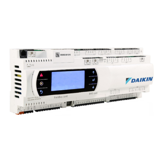
Summary of Contents for Daikin iLINQ
- Page 1 QSG-ILINQA Daikin iLINQ Quick Start Guide...
-
Page 2: Table Of Contents
Unit Configuration Settings ........................18 Temperature/Humidity Setpoints ......................19 Timers/Delays ............................20 Modify TCP/IP Settings ......................... 20 View Active Alarms ..........................21 Test and Balance ........................... 21 Export Parameters ..........................23 Quick Start Checklist ..........................25 DAIKIN ILINQ QUICK START GUIDE... -
Page 3: Outline
This guide provides procedures that should be followed for the successful implementation of the Daikin iLINQ controller. For more detailed information on any of the features or wiring, please refer to the Daikin iLINQ User Manual and the wiring diagram provided with the unit. -
Page 4: Installation
24VAC power wiring at terminal J1 is correct. The transformer secondary, wired to G0, must be connected to earth ground. Using a supply voltage other than specified may cause damage to the controller. DAIKIN ILINQ QUICK START GUIDE... -
Page 5: Space Temperature Sensor
In some cases, controller terminal J6 may be factory wired to a more easily accessible set of terminals in the unit control box. Refer to the wiring diagram supplied with the unit for additional details. DAIKIN ILINQ QUICK START GUIDE... -
Page 6: Supply Air Temperature Sensor
In some cases, controller terminal J2 may be factory wired to a more easily accessible set of terminals in the unit control box. In this case, the sensor is wired between DAT and AG on the control box terminals. Refer to the wiring diagram supplied with the unit for additional details. DAIKIN ILINQ QUICK START GUIDE... -
Page 7: Using The Onboard Display
After successfully logging in, the Main Menu is displayed. Navigate through the Main Menu screens using the UP and DOWN buttons to highlight menu options and pressing the ENTER button to select. DAIKIN ILINQ QUICK START GUIDE... -
Page 8: Configure Date/Time
Schedule Events are composed of a Start Time and an End Time for occupancy. Setting the Start Time equal to the End Time is considered unoccupied all day. Setting the Start Time to 12:00 AM and the End Time to 11:59 PM is considered occupied all day. DAIKIN ILINQ QUICK START GUIDE... -
Page 9: Unit Configuration Settings
Use the UP or DOWN button to toggle the value and press ENTER to accept. This process is repeated for the start and stop time settings for the four events. Additional information on time schedule settings is provided in the Daikin iLINQ User Manual. Unit Configuration Settings Select the Unit Configuration option from the Main Menu to verify that the unit configurations are correct. -
Page 10: Temperature/Humidity Setpoints
Select Temperature/Humidity Setpoints from the Main Menu. Scroll through the setpoints and modify factory settings per site requirements. Additional information on temperature and humidity setpoints is provided in the Daikin iLINQ User Manual. Timers/Delays Select Timers/Delays from the Main Menu. Scroll through the timers/delays and modify factory settings per site requirements. -
Page 11: Modify Tcp/Ip Settings
Main Menu, navigate to Test/Balance and press ENTER to view the Force Mode screen. Force Mode allows the user to select from a set of predefined modes. Depending on the Force Mode selected, the controller commands the necessary outputs based on the unit configuration. In DAIKIN ILINQ QUICK START GUIDE... - Page 12 IO manual, navigate to the Econ/Blower Settings screen. From the Main Menu, navigate to Econ/Blower Stpts and press ENTER to view or modify all of the economizer and blower speed settings. DAIKIN ILINQ QUICK START GUIDE...
-
Page 13: Export Parameters
Selecting USB will save the file to a connected USB device. Reference the web interface export parameters section of this guide for instructions on accessing and retrieving the export file from the controller’s internal memory. DAIKIN ILINQ QUICK START GUIDE... -
Page 14: Using The Web Interface
Ethernet ports. Modify the computer’s network settings so the IP address is in the range: 192.168.1.1 to 192.168.1.254 (excluding 192.168.1.16 which is used by the controller). The Subnet Mask should be set to 255.255.255.0 and the Default Gateway can be left un- configured. DAIKIN ILINQ QUICK START GUIDE... -
Page 15: Web Access Code
Click in the entry field for each account and type a four digit numeric password that will be used for access to the web interface and the onboard LCD display. After pressing enter or clicking the save button, the login screen is displayed. DAIKIN ILINQ QUICK START GUIDE... -
Page 16: Web Interface Access
192.168.1.16 into the address bar and press enter. When prompted for a password, enter the user or service password. After successfully logging in, the Main Screen is displayed. Navigate through the Web Interface screens using the navigation menu on the left side of the screen. DAIKIN ILINQ QUICK START GUIDE... -
Page 17: Configure Date/Time
Update Date/Time toggle switch. Alternatively, clicking the Sync Date/Time toggle switch sets the controller date and time to the same values as the date and time on the connected PC. The user must still manually update the timezone if the sync date/time feature is used. DAIKIN ILINQ QUICK START GUIDE... -
Page 18: Configure Time Schedule
• commands from a traditional thermostat instead of using the DDC controller application logic. Follow wiring modification steps outlined in the Daikin iLINQ User Manual. Setting the Blower Cycling toggle switch to Enabled allows the main blower to be cycled •... -
Page 19: Temperature/Humidity Setpoints
Force Unoccupied to bypass scheduling. Temperature/Humidity Setpoints Select Parameters → Temperature/Humidity Setpoints from the Main Menu. Modify factory setpoints per site requirements. See the Daikin iLINQ User Manual supplied with the unit for a detailed description of each setpoint. DAIKIN ILINQ QUICK START GUIDE... -
Page 20: Timers/Delays
Timers/Delays Select Parameters → Timers/Delays from the Main Menu. Modify factory timer/delay settings per site requirements. See the Daikin iLINQ User Manual supplied with the unit for a detailed description of each setting. Modify TCP/IP Settings If the controller is to be connected to a TCP/IP network, the TCP/IP settings must be provided by the network administrator. -
Page 21: View Active Alarms
Unit → Test/Balance screen in the Navigation Menu to place the unit into Force Mode. Force Mode allows the user to select from a set of predefined modes. Depending on the Force Mode selected, the controller commands the necessary outputs based on the unit configuration. DAIKIN ILINQ QUICK START GUIDE... - Page 22 If it is determined that economizer minimum positions or blower speed settings need to be adjusted to meet airflow requirements for the site or to match the airflow tables in the unit IO manual, navigate to the Parameters → Econ/Blower Settings screen in the Navigation Menu. DAIKIN ILINQ QUICK START GUIDE...
-
Page 23: Export Parameters
Connect the controller to the PC via a USB-A to USB-B cable and open windows explorer. The controller will appear as a removable disk. Open the controller and copy the site- specific export file to the PC. Do not rename or move the EXPORT_99.txt file. (Continued on next page) DAIKIN ILINQ QUICK START GUIDE... - Page 24 DAIKIN ILINQ QUICK START GUIDE...
-
Page 25: Quick Start Checklist
Heating High: Heating High: Heating High: Enter Set-points to Comply With Site Requirements Create Site Parameter Export File Once Controller Configuration is Finalized Temperature/Humidity Set-points Timers/Delays Export File Name: Comments: Comments: DAIKIN ILINQ QUICK START GUIDE... - Page 26 WARNING • Only qualified personnel must complete the installation. • Consult your Daikin dealer/contractor regarding relocation and reinstallation of the remote controller. Improper installation may result in electric shock or fire. • Electrical work must be performed in accordance with relevant local and national regulations, and with the instructions in this installation manual.
Need help?
Do you have a question about the iLINQ and is the answer not in the manual?
Questions and answers