Daikin Maverick I Operation Manual
Package air conditioner ddc rooftop unit controller
Hide thumbs
Also See for Maverick I:
- Installation and maintenance manual (52 pages) ,
- Installation and maintenance manual (97 pages)
Table of Contents
Advertisement
Quick Links
Advertisement
Table of Contents

Related Manuals for Daikin Maverick I


Summary of Contents for Daikin Maverick I
- Page 1 Operation Manual OM 1077-1 Group: Applied Air Systems Part Number: OM 1077 Date: July 2016 Maverick I Package Air Conditioner ® DDC Rooftop Unit Controller Heating & Cooling, Gas/Electric and Electric/Electric Models MPS 003B – 025B 3 to 25 Tonns [10.6 to 87.9 kW] R-410A Refrigerant...
-
Page 2: Table Of Contents
Data ........47 OM 1077-1 • MAVERICK I... -
Page 3: Introduction
General Read this manual and any instructions packaged with separate The Maverick I 3 to 25 ton Package has a Rooftop Unit equipment prior to installation. Give this manual to the owner Controller factory mounted and wired in their respective control and explain its provisions. -
Page 4: Programmable 24 Volt Thermostat
The DDC Controller in each Maverick I 3 to 25 ton Package Air • Staging. Depending on the unit controls up to 2 stages... - Page 5 MOD1 LED blinks when the control is communicating on the internal network between the IFC and/or economizer MOD2 LED MOD2 LED blinks when the control is communicating between the DDC Controller and field installed communication card www.DaikinApplied.com OM 1077-1 • MAVERICK I...
-
Page 6: Control Inputs And Outputs
If the remote set point adjustment is enabled but the input reads an invalid number, the control will default back to the occupied set point selection. OM 1077-1 • MAVERICK I www.DaikinApplied.com... - Page 7 LCD display if the pressure differential indicates that the indoor blower is not operating. The control will also monitor the system and if the blower is running and is not required a fault will be sent to the DDC Controller. www.DaikinApplied.com OM 1077-1 • MAVERICK I...
-
Page 8: Control Outputs
24 V thermostat equipped with an “L” 18 AWG Wall mounted sensor terminal. 113117701 Solid 3/C CL2P with tenant override Thermostat Wall mounted sensor 18 AWG with space point 113117701 Solid 3/C CL2P adjustment Thermostat OM 1077-1 • MAVERICK I www.DaikinApplied.com... -
Page 9: Unit Installation
Figure 2. This is necessary to meet National Electrical Code (NEC) and UL 1995 requirements for separation of high and low Conduit for Low voltage circuits. Voltage Conductors www.DaikinApplied.com OM 1077-1 • MAVERICK I... -
Page 10: Stand Alone With Thermostat
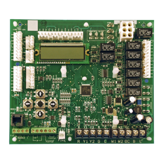
Occupancy Compressor Signal Indoor Fan 2nd Stage Heat 24V Common 1st Stage Heat Figure 4: Standalone with Zone Sensor and Time Clock Zone Sensor 10k Thermistor Time Clock Override Button 10k Pot Setpoint Adj. OM 1077-1 • MAVERICK I www.DaikinApplied.com... -
Page 11: Standalone With Building Automation System
2nd-party building automation system that will be controlled from a central location. Figure 5: Zone Sensor with Building Automation System Zone Sensor 10k Thermistor Override Button 10k Pot Setpoint Adj. BACnet Daughter Board LONWorks Daughter Board www.DaikinApplied.com OM 1077-1 • MAVERICK I... -
Page 12: Indoor Relative Humidity Sensor
BAS communication card and a third-party BAS that will be controlled from a central location. Figure 6: Indoor Relative Humidity Connection 24VDC Humidity Sensor OM 1077-1 • MAVERICK I www.DaikinApplied.com... -
Page 13: Sequence Of Operation
IFC will respond with a fault code and it will flash code “2” on the LED, waiting indefinitely for both pressure switches to open. If both pressure switches are open, the IFC proceeds to prepurge. www.DaikinApplied.com OM 1077-1 • MAVERICK I... - Page 14 Low gas, low inducer, and the delay OFF time. blower remain energized. If the DDC Controller calls for 2nd stage heat (Hi Heat), the IFC transitions to high heat. OM 1077-1 • MAVERICK I www.DaikinApplied.com...
- Page 15 The continuous fan operation continues to function while the purge time with high gas output energized to begin a re-ignition control is in heat mode lockout. attempt. The indoor blower remains on (for the delay OFF time) through the re-ignition attempt. www.DaikinApplied.com OM 1077-1 • MAVERICK I...
- Page 16 The electric heat is energized whenever the demand for heat unburned gas. is not satisfied. The heat source it will be staged on based on demand. During electric heat operation the control does not delay energizing the indoor fan. OM 1077-1 • MAVERICK I www.DaikinApplied.com...
-
Page 17: User Interface
Enter key again for the change to take effect. During the adjustment, either left or right keys work as “escape” so the parameter reverts back to its original value and the cursor is no longer visible. Left Right Enter Down www.DaikinApplied.com OM 1077-1 • MAVERICK I... - Page 18 Defrost Mode Eff. DCV Level All Sub-Menus highlighted gray Acc defrost time Dff. Eco Position are user adjustable Defrost SCT lim. Eff. Min. Position Defrost Comp. Off Local Min. Pos. Econ. Faults Econ Firm Vrsn OM 1077-1 • MAVERICK I www.DaikinApplied.com...
-
Page 19: General Information Screen
Rev Vlv 2 – ON/OFF Outputs Heat 1 – ON/OFF Heat 2 – ON/OFF Outdr Fan 1 – ON/OFF Outdr Fan 2 – ON/OFF Indoor Fan – ON/OFF Capacity Heating / Cooling – 100% www.DaikinApplied.com OM 1077-1 • MAVERICK I... -
Page 20: Effective Occupancy Screen
2 seconds. The Tenant Override period is adjustable between 2 and 6 hours and it has priority over any other settings. All set points are available via network and local human interface. OM 1077-1 • MAVERICK I www.DaikinApplied.com... -
Page 21: Temperature Screen
The DDC Controller will consider the hardwired potentiometer reading or the network remote set point adjustment as the cooling set point. It calculates the heating set point by subtracting dead band (2.0°F) and differential from the cooling set point. www.DaikinApplied.com OM 1077-1 • MAVERICK I... -
Page 22: Economizer
Eff.Eco.Position 5°F below the set point. Eff.Min.Position Local. Min. Pos. DCV Sensor Fault OAE Sensor Fault Econ. Faults RAE Sensor Fault MAT Sensor Fault Econ Firm Vrsn 0103 * Menus that are user adjustable OM 1077-1 • MAVERICK I www.DaikinApplied.com... - Page 23 The economizer will allow the dampers to close more than the minimum position if the indoor air quality is not contaminated. The Econ. DCV Limit can be set from 0 to 100% but must be lower than the minimum position. www.DaikinApplied.com OM 1077-1 • MAVERICK I...
-
Page 24: Integrated Furnace Control Screen
Note: The actuator fault must be present for at least 2 minutes with the unit powered, the indoor fan running, and the outside damper commanded to open more than 0% before the alarm is set. OM 1077-1 • MAVERICK I www.DaikinApplied.com... -
Page 25: Time Delays Screen
The anti short cycle delay is an adjustable delay used to keep button on the space sensor for more than 2 seconds. the compressor from re-energizing too quickly after a cycle. The delay time starts after the compressor de-energizes. www.DaikinApplied.com OM 1077-1 • MAVERICK I... -
Page 26: Humidity Control
Table 14 Table 15 explain the various modes available. OM 1077-1 • MAVERICK I www.DaikinApplied.com... - Page 27 Y1 - First stage cooling call from thermostat or network Y2 - Second stage cooling call from thermostat or network *1st stage cooling speed has a default value of 50% of high fan speed www.DaikinApplied.com OM 1077-1 • MAVERICK I...
-
Page 28: Variable Frequency Drive
NOTE: If the indoor fan is ramping up to speed from a dead stop, the Low Fan Speed will briefly ramp to 75% of the full speed in order to “set” the fan proving switch and confirm proof of indoor airflow. OM 1077-1 • MAVERICK I www.DaikinApplied.com... -
Page 29: Alarm List
• Expansion valve in not operating AC Low Pressure Switch 2 Trip-LP2 DDC Controller outdoor ambient temperature rises above 5 °F. LPS correctly is ignored during defrost. www.DaikinApplied.com OM 1077-1 • MAVERICK I... - Page 30 • Low line voltage to compressor Duct High Limit Fault Future implementation Indicates that a combination of thermostat inputs Invalid Thermostat selection is invalid. Leave inducer de-energized until pressure switch Pressure Switch 1 Closed • Bad Pressure Switch open OM 1077-1 • MAVERICK I www.DaikinApplied.com...
- Page 31 • Broken belt • Indoor motor running backwards (3 phase) • Open internal motor protector • Replace the sensor ELM - OAE Sensor Fail Sensor short, failure • Check sensor is installed correctly on control www.DaikinApplied.com OM 1077-1 • MAVERICK I...
- Page 32 • Replace the sensors Indicate presence of the alarm and convert Space Sensor & Return Sensor Fail DDC Controller • Check sensors are installed correctly operation to thermostat mode. on control OM 1077-1 • MAVERICK I www.DaikinApplied.com...
- Page 33 Three occurrences of a high pressure High Pressure – Circuit 2 Problem - Lockout DDC Controller switch within the same call will lock the circuit out. • Excessive refrigerant charge The lockout is reset by removing the call. www.DaikinApplied.com OM 1077-1 • MAVERICK I...
-
Page 34: Quick Start
3. Wait until cursor on display flashes 4. SCROLL DOWN OCCUPIED MODE 5. Chose Ctrl by Tstat Ctrl by Tstat All Sub-Menus highlighted gray are 6. Briefly press [Enter] user adjustable UNIT 7. Wait until cursor stops flashing KEYPAD OM 1077-1 • MAVERICK I www.DaikinApplied.com... -
Page 35: Wiring Diagrams
IrIng IagraMs IrIng IagraMs Figure 12: MPS003B-MPS005B, 208-230/460V, 3-Phase, Gas Heat www.DaikinApplied.com OM 1077-1 • MAVERICK I... - Page 36 IrIng IagraMs Figure 13: MPS003B-MPS005B, 575V, 3-Phase, Gas Heat Controller OM 1077-1 • MAVERICK I www.DaikinApplied.com...
- Page 37 IrIng IagraMs Figure 14: MPS006B-MPS007B, 208-230/460V, 3-Phase, Gas Heat Controller www.DaikinApplied.com OM 1077-1 • MAVERICK I...
- Page 38 IrIng IagraMs Figure 15: MPS006B-MPS007B, 575V, 3-Phase, Gas Heat Controller OM 1077-1 • MAVERICK I www.DaikinApplied.com...
- Page 39 IrIng IagraMs Figure 16: MPS008B-MPS012B, 208-230/460V, 3-Phase, Gas Heat Controller www.DaikinApplied.com OM 1077-1 • MAVERICK I...
- Page 40 IrIng IagraMs Figure 17: MPS008B-MPS012B, 575, 3-Phase, Gas Heat Controller OM 1077-1 • MAVERICK I www.DaikinApplied.com...
- Page 41 IrIng IagraMs Figure 18: MPS015B-MPS025B, 208-230/460V, 3-Phase, Gas Heat Controller www.DaikinApplied.com OM 1077-1 • MAVERICK I...
- Page 42 IrIng IagraMs Figure 19: MPS015B-MPS025B, 575V, 3-Phase, Gas Heat Controller OM 1077-1 • MAVERICK I www.DaikinApplied.com...
- Page 43 IrIng IagraMs Figure 20: MPS003B-MPS005B, 208-230/460V, 3-Phase, Cooling Only www.DaikinApplied.com OM 1077-1 • MAVERICK I...
- Page 44 IrIng IagraMs Figure 21: MPS006B-MPS007B, 208-230/460/575V, 3-Phase, Cooling Only Controller OM 1077-1 • MAVERICK I www.DaikinApplied.com...
- Page 45 IrIng IagraMs Figure 22: MPS008B-MPS012B, 208-230/460/575V, 3-Phase, Cooling Only Controller www.DaikinApplied.com OM 1077-1 • MAVERICK I...
- Page 46 IrIng IagraMs Figure 23: MPS015B-MPS025B, 208-230/460/575V, 3-Phase, Cooling Only Controller OM 1077-1 • MAVERICK I www.DaikinApplied.com...
-
Page 47: Data
140.0 2,488 215.6 289.4 68.0 12,493 141.8 2,400 217.4 291.2 69.8 11,942 143.6 2,315 219.2 293.0 71.6 11,418 145.4 2,235 219.9 294.8 73.4 10,921 147.2 2,157 221.0 296.6 75.2 10,449 149.0 2,083 222.8 298.4 www.DaikinApplied.com OM 1077-1 • MAVERICK I... - Page 48 Daikin Applied Training and Development Now that you have made an investment in modern, efficient Daikin equipment, its care should be a high priority. For training information on all Daikin HVAC products, please visit us at www.DaikinApplied.com and click on Training, or call 540-248-9646 and ask for the Training Department.
Need help?
Do you have a question about the Maverick I and is the answer not in the manual?
Questions and answers